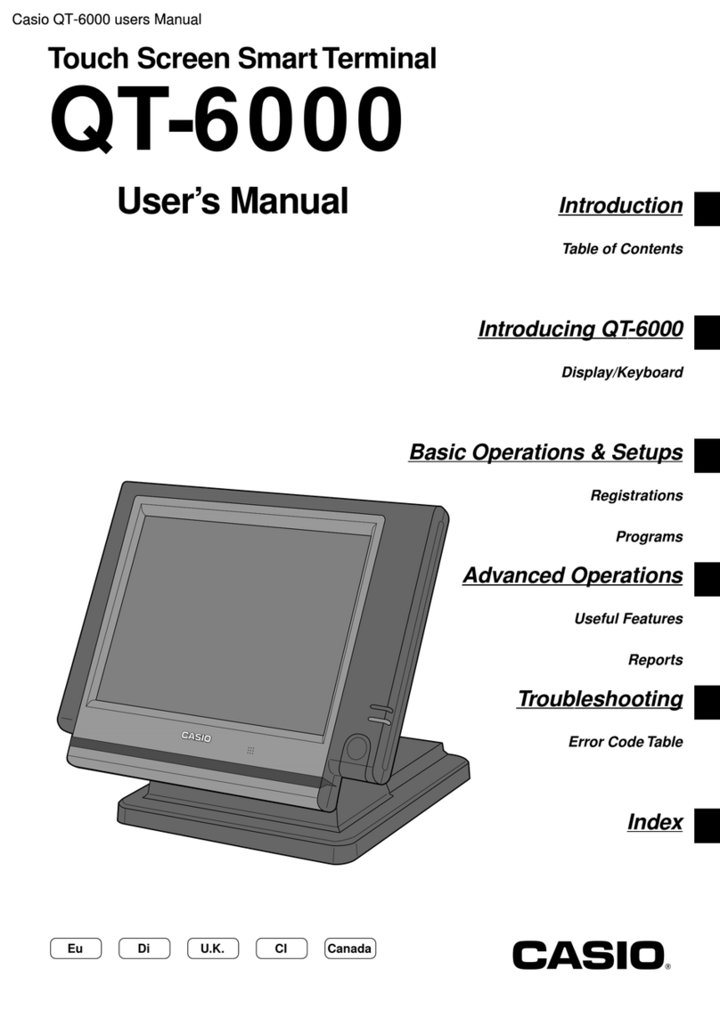
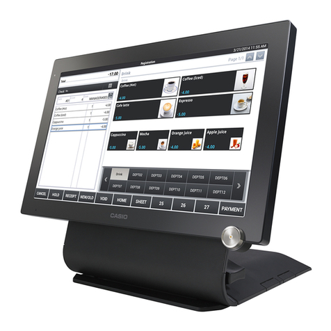
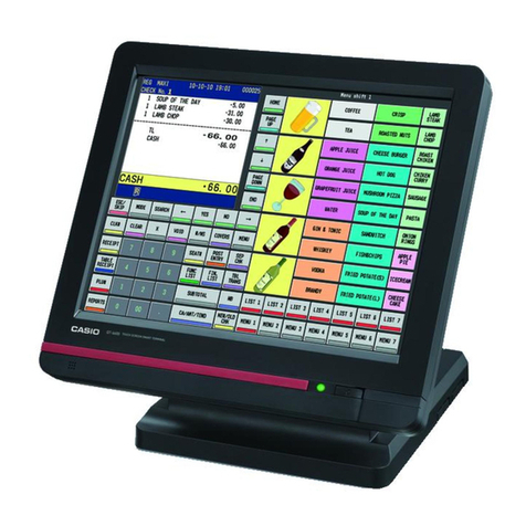
Casio QT-8000 User manual

CONTENTS
QT-8000 PAGE
1. EXPLANATION OF PRODUCT...............................................................................1
1-1. GENERAL DESCRIPTION .......................................................................................... 1
1-2. SYSTEM OVERVIEW .................................................................................................. 1
1-3. MAJOR COMPONENT ................................................................................................ 2
1-4. SPECIFICATIONS ....................................................................................................... 4
1-5. I/O OUTLETS ............................................................................................................... 6
1-6. OPTION........................................................................................................................ 7
2. DISASSEMBLY .......................................................................................................8
3. INSTALLATION .....................................................................................................17
4. OPTION INSTALLATION ......................................................................................20
4-1. INSTALLING THE DISPLAY SET FOR CUSTOMER (QT-6060D) ........................... 20
4-2. INSTALLING THE LONG POLE................................................................................ 22
5. SYSTEM INSTALLATION .....................................................................................23
5-1. CPU ............................................................................................................................ 23
5-2. DRAM......................................................................................................................... 24
5-3. HDD ............................................................................................................................ 24
5-4. SERIAL PORTS ......................................................................................................... 24
5-5. PARALLEL PORT ..................................................................................................... 24
5-6. VGA ............................................................................................................................ 25
5-7. ETHERNET ................................................................................................................ 25
5-8. KEYBOARD ............................................................................................................... 25
5-9. PS/2 MOUSE.............................................................................................................. 25
5-10. SYSTEM O/S AND SOFTWARE INSTALLATION .................................................... 26
5-11. AWARD BIOS SETUP ............................................................................................... 26
5-12. TOUCH SCREEN....................................................................................................... 45
5-13. ETHERNET INTRODUCTION.................................................................................... 46
6. DIAGNOSTIC OPERATION ..................................................................................48
6-1. INSPECTION OF A LAN............................................................................................ 48
6-2. INSPECTION OF USB ............................................................................................... 48
6-3. INSPECTION OF COM (RS232C) ............................................................................. 49
6-4. LCD INSPECTION ..................................................................................................... 49
6-5. INSPECTION OF THE TOUCH PANEL .................................................................... 50
6-6. INSPECTION OF HDD............................................................................................... 50
6-7. INSPECTION OF RTC ............................................................................................... 51
7. CIRCUIT EXPLANATIONS....................................................................................52
7-1. EXPLANATIONS OF EACH BLOCK ........................................................................ 52
7-2. BLOCK DIAGRAM..................................................................................................... 55
7-3. JUMPER SETTING .................................................................................................... 57
8. TROUBLESHOOTING...........................................................................................63
9. DATA SHEET ........................................................................................................66
9-1. POWER SUPPLY....................................................................................................... 66
10. PART LIST.............................................................................................................67
DO NOT REMOVE OR INSERT A CF CARD WHILE THE POWER IS ON (WHILE THE
POWER LED LIGHTS GREEN).
DOING SO MAY CAUSE THE DATA INSIDE THE CF CARD OR THE CF CARD ITSELF TO
BE DAMAGED IN THE WORST CASE.
NOTE
-1-
1. EXPLANATION OF PRODUCT
1-1. General Description
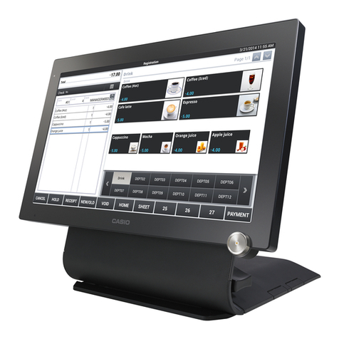
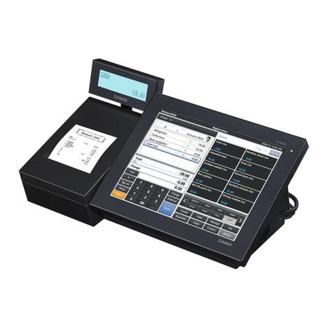
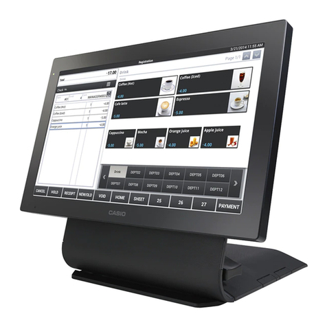
The QT-8000 is a PC-based POS terminal which integrates XGA 15”LCD panel, Touch
screen, Ethernet, USB, COM port, parallel port, Audio, PS/2 Keyboard, mouse, etc.
The QT-8000 features desktop free standing and wall mounting for a wide variety of
applications. Aunique cable management device is also provided to trim the operation
environment. In conformity to IPX1 standard, water-resistant system design is adopted.
Designed by the PC and POS experts for the POS professionals, the QT-8000 is virtually
the ultimate solution for hospitality applications.
1-2. System Overview

-2-
1-3. Major Component
1. Touch Panel:
The QT-8000 features a quick-response touch screen for keyboardless operation. The
standard touch adapted in this system is 15" analog resistive type touch screen. Its
durability is 10 million touches in life.
2. LCD Panel :
To provide the best visual resolution and viewing angle, the standard display panel
adapted in the QT-8000 is 15" TFT LCD Panel.
(1) Resolution: XGA 1024(H) x 768(V)
(2) Brightness: 250 nit
(3) Contrast Ratio: 400: 1 (typical)
(4) Support Colors: 262,144 colors (6-bit for R,G,B)
(5) Titling Angle: 15 ~ 75 degrees
3. IButton:
By using the electronic key equipped with a DS1990A,the iButton magnetic probe can
be used as the access control to the POS terminal.
4. LED LENS:
LED lens consist of one Power LED indicator with green color and one HDD LED
indicator with orange color.
5. Card Reader
The card reader consists of a magnetic stripe which is used to read the credit card. It
can support ISO track 1&2 standard or ISO track 2 & JISII standard.
6. Panel Back:
The plastic panel back is used to cover the LCD panel with the inner sheet metal
attached to it.
7. CF Cover:
Inside the CF cover, user can find one Compact flash socket supporting Type I / II,
software power switch and LCD brightness control.

-3-
8. CF Cover Lock:
The CF cover lock is used to hold the items inside the CF cover.
9. Rotate Cover:
The rotate cover is made of amixture of PC and ABS material and it is used to prettify
the back of the LCD panel by covering the hangers.
10.Stand Hinge:
The hinge is located at both right and left sides of the LCD panel. User can adjust the
display angle of the LCD panel up and down by turning the hinge.
11.Cable Management Shroud:
The shroud is made of amixture of PC and ABS material. It is used to hide the cables
coming down from the bottom side of the chassis and to make the operation
environment look trimmed.
12.Stand:
The stand is made up by an aluminum metal piece. It is used to ensure the stability
when a certain touch pressure is exerted on the touchscreen.

-4-
1-4. Specifications
Core System (Motherboard)
•CPU: Intel® Celeron™ 1.2GHz, Socket 370 processor
with
FC-PGA2 package type
•System Chipset: VIA CLE266 (VT8623) North Bridge and
VT8235 South
Bridge
•BIOS: Phoenix Award PnP BIOS, 4M bits Flash ROM
with VGA
BIOS
•System Memory: 1x184-pin DDR SDRAM socket supports up to 1GB.
•L2 Cache: Integrated in CPU
•Real Time Clock: Accuracy is within +/-60sec monthly at 25°C
I/O system
•Front side 1 x Power LED ( Green Color)
1 x HDD LED (Orange Color)
1 x MSR
1 x iButton (Magnetic Probe)
•Rear side 1 x DC19V input Jack
1 x DC Power Switch
1 x RJ45 with LED, support 10/100 Mbps Ethernet LAN
4 x USB2.0 ports
4 x COM port with +5V/+12V voltage selection at 9th pin
1 x Parallel port
1 x VGA port
1 x Line-Out
1 x MIC
1 x mini-Din 6-pin for Keyboard
1 x mini-Din 6-pin for PS2 Mouse
•Right Side 1 x Compact Flash Card Socket
1 x Variant Resistor for LCD Brightness Control
1 x Power Button

-5-
Built-in Peripherals
•2.5”Hard disk (designed 30GB)
•15”5-wire resistive type touch screen via USB interface
•MSR Card Reader (Optional)
System Specification
•15”TFT LCD display, resolution 1024 x 768
•One Compact flash socket with Type I / II
•120W power supply
•Dimension (main body size): 362 (W)x 345(D) x 361 (H)
•System Weight: 11.7 Kg (including packing material)
•Operating Temperature: 0°C~35°Cunder humidity at 10 ~ 90%RH
• Storage Temperature: -25°C ~ 65°Cunder humidity at 10 ~ 95%RH
•Regulation:
(1) EMC CLASS-A: CE, FCC,VCCI, C-Tick
(2) Safety: PSE, UL, cUL, CB
Note: 1) Specifications subject to change without notice.
2) The mouse and the P/C keyboard are designed for the engineers who are
trained to use them for installation of the POS terminal and are not
recommended to use at customer site as regular POS function in store hours.
It may cause fail of the radiation regulation (ie. FCC or CE).

-6-
9) Parallel port
10)DC-In jack
11)Power switch
1-5. I/O Outlets
The following diagram shows the I/O arrangement.
Bottom Panel
Side Panel
5) Mouse
6) 4 x USB 2.0
7) 4 x COM ports
8) Second VGA
1) Ethernet 10/100 Base-T
2) MIC
3) Audio Out
4) Keyboard
1) Brightness
2) CF Card
3) Power switch

-7-
1-6. Option
DEVICE NAME MODEL NOTE
• Display set for customer QT-6060D
• Display cable for customer
(for mounting to the base) QT-6061CB
• Display 5-meter cable for
customer QT-6062CB
• Remote printer UP-360
• Printer cable PRT-CB-8A (Length 3m)
• Printer cable PRT-CB-8B (Length 5m)
• Cash Tray CTR-53
• Tray Lid SLD-9
• MCR
QT-6046MCR
Drawer
DRAWER NAME Specification NOTE
• DL-3401 (L type) D-22BH-A55SM-17

-8-
2. DISASSEMBLY
STEP 1: Remove HDD Cover.
STEP 2: Remove HDD.
Pull out the HDD cable.
Release the 4 screws.

-9-
STEP 3: Remove Card Reader Cover.
STEP 4: Remove Back Cover.
Release the 3 screws.
Release the 15 screws.

-10 -
STEP 5: Remove Chassis_T.
STEP 6: Remove CF Board, MSR Board.
Release the 6 screws.
Release the 5 screws.

-11 -
STEP 7: CF Board, MSR Board.
STEP 8: Release the I/O connectors’copper pillars.
CF Board
MSR Board
Release the 12 copper pillars.

-12 -
STEP 9: Remove Main Board.
STEP 10: Main Board.
Release the 5 copper pillars.
Release the 4 screws

-13 -
STEP 11: Remove Inverter Board.
STEP 12: Inverter Board.
Release the 2 screws.

-14 -
STEP 13: Remove the Control Board of Touch Panel.
STEP 14: Control Board of Touch Panel.
Release the 2 screws.

-15 -
STEP 15: Remove Base.
STEP 16: Remove LCD Panel.
Remove 14 screws.
Remove 4screws from both side of system base.

-16 -
STEP 17: Remove Touch Panel.
Remove Touch Panel.

-17 -
3. INSTALLATION
Unpacking
The QT-8000 along with its accessories are packed in carton box. After unpacking the carton,
place the system on a raised surface and carefully inspect the system for any damage that
might have occurred during shipment. If there are damaged or missing parts, contact your
dealer immediately.
Hardware system installation procedure:
2.
1.
3.
4.

-18 -
5.
6.
7.
8.
9.
10.
Table of contents
Other Casio Touch Terminal manuals

Casio
Casio QT-6000 User manual

Casio
Casio QT-6600 User manual

Casio
Casio QT-2100 User manual

Casio
Casio V-R7100 User manual

Casio
Casio QT-6600 User manual

Casio
Casio IT-9000C User manual

Casio
Casio V-REGI Series User manual

Casio
Casio IT-3100 User manual

Casio
Casio DT-X10M10E User manual

Casio
Casio DT-X8 Series User manual

Casio
Casio DT-X10 series User manual

Casio
Casio DT-X450 Series User manual

Casio
Casio V-REGI Series User manual

Casio
Casio IT -G500 Series User manual

Casio
Casio QT-6600 Owner's manual

Casio
Casio ET-L10 Series User manual

Casio
Casio QT-2000 User manual

Casio
Casio QT-6600 User manual

Casio
Casio V-REGI Series User manual

Casio
Casio IT-500 Series User manual