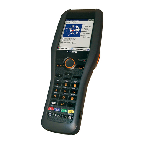
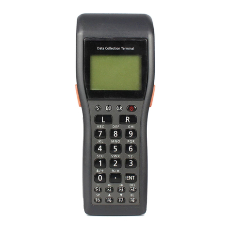
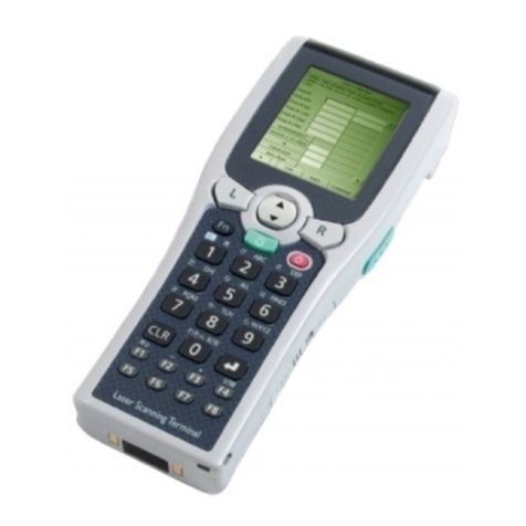
Casio DT-940 User manual

SERVICE MANUAL
HANDHELD TERMINAL
DT-930 / DT-940(PY-050)
MAY. 2006
DT-930
Ver.3 : Dec. 2011

CONTENTS
Page
1. GENERAL ................................................................................................................1
2. FUNCTION AND BASIC OPERATION ....................................................................6
3. DISASSEMBLY/ASSEMBLY ................................................................................. 11
4. DIAGNOSTIC PROGRAM .....................................................................................23
5. BAR CODE CALIBRATION SETTING ..................................................................48
6. TECHNICAL INFORMATION.................................................................................51
7. EXPLODED VIEW..................................................................................................54
8. PARTS LIST ...........................................................................................................59
APPENDIX HA-E60IO (EXPLODED VIEW)......................................................64
HA-E60IO (PARTS LIST)...............................................................65

― 1 ―
1. GENERAL
1.1 LINE UP
Model Name
Features
Bluetooth Memory Reader Port Released
RAM ROM
DT-930M50E 4 MB 16 MB Down-facing reader port May/2006
DT-930M51E 4 MB 16 MB Forward-facing reader port May/2006
DT-930M50NBE Í4 MB 16 MB Down-facing reader port May/2006
DT-930M51NBE Í4 MB 16 MB Forward-facing reader port May/2006
DT-930M50G 4 MB 16 MB Down-facing reader port Nov/2006
DT-930M50E-CN 4 MB 16 MB Down-facing reader port Jan/2007
DT-930M51E-CN 4 MB 16 MB Forward-facing reader port Jan/2007
DT-930M50NBE-CN Í4 MB 16 MB Down-facing reader port Jan/2007
DT-930M51NBE-CN Í4 MB 16 MB Forward-facing reader port Jun/2007
DT-930M50E-2-CN 4 MB 16 MB Down-facing reader port Mar/2011
DT-940M51NBE-CN Í4 MB 16 MB Forward-facing reader port Mar/2011
DT-940M51E-CN 4 MB 16 MB Forward-facing reader port May/2011
1.2 OPTIONS
For repair
: Service parts are available.
Í: No Repair. When it breaks down, please purchase the product newly from the Sales.
HA-E60IO
Bridge Basic Cradle
For repair:
Interface: Infrared interface (IrDA Ver1.1)
Speed: 4 Mbps (MAX)
USB (Ver1.1)
Spped: 12 Mbps (MAX)
AC Adaptor: AD-S15050AE (AC 100 to 240V)
DT-960IOE
Basic Cradle
For repair:
Interface: RS-232C .....Speed: 2,400 to 115,200 bps
RS-485........Speed: 2,400 to 115,200 bps
AC Adaptor: DT-9020ADP-GS (AC 230V)
DT-9020ADP-US (AC 120V)
DT-964IOE
Satellite Cradle
For repair:
Interface: RS-232C .....Speed: 1,200 to 115,200 bps
RS-422........Speed: 9,600/38,400/115,200 bps
AC Adaptor: AD-S42120AE (AC 100 to 240V)

― 2 ―
DT-969CHGE
Cradle type Battery Charger
For repair: O
AC Adaptor: DT-9020ADP-GS/DT-9020ADP-US
Charge time: Approx. 6 hours
DT-923LIB
Lithium-ion Battery Pack
Rated Capacitance: 540mAh
Rated Voltage: 3.6V
AD-S15050AE
AC Adaptor for Bridge Basic Cradle (HA-E60IO)
For repair: Í
Input: AC 100-240V, 50-60Hz
Output: DC5V, 3.0A
DT-9020ADP-GS/DT-9020ADP-US
AC Adaptor for Basic Cradle (DT-960IOE) and Cradle type
Battery Charger (DT-969CHGE)
For repair: Í
Input: DT-9020ADP-GS (230 VAC)
DT-9020ADP-US (120 VAC)
Output: DC9.5V, 1.0A
AD-S42120AE
AC Adaptor for Satellite Cradle (DT-964IOE)
For repair: Í
Input: AC 100-240V, 50-60Hz
Output: DC12V, 3.5A
HA-E90BP
Bumper
For a harsh working enrironment who requires a higher grade of impact
resistance.
Cables:
RS-232C cable DT-782RSC Cross-cable for Basic Cradle 14Pin-25Pin (male)
RS-232C cable DT-783RSC Cross-cable for Basic Cradle 14Pin-25Pin (female)
RS-232C cable DT-787AX Cross-cable for Basic Cradle 14Pin-9Pin (female)
RS-232C cable DT-881RSC Straight cable for Satellite Cradle For modem connection
RS-232C cable DT-882RSC Cross-cable for connecting Satellite Cradle 25Pin (male)
to personal computer
RS-232C cable DT-883RSC Cross-cable for connecting Satellite Cradle 25Pin (female)
to personal computer
RS-232C cable DT-887AX/AXA Cross-cable for connecting Satellite Cradle 9Pin (female)
to personal computer
RS-485 cable DT-788RSC 6-6 pin modular cable or daisy-chaining
Basic Cradle
RS-422 cable DT-888RSC For daisy-chaining Satellite Cradle
USB cable DT-380USB Bridge Basic Cradle to personal computer

― 3 ―
1.3 SPECIFICATIONS
•General
CPU: 32-bit RISC Type
Memory: RAM : 4MB (User area 1.6 MB)
FROM : 16MB (User area 12.5 MB)
•Display
Type: STN LCD with phase correction lm
Capacity: 128 x 64 dots
Display contrast: Manually adjustable
Backlight: LED
•LaserScanner
Frontage: Forward-facing reader port model: 0 degrees
Down-facing reader port model: 60 degrees
Wavelength: 650 ± 10 nm
Optical Output: Less than 1 mW
No. of scans: 100 ± 20 scan/sec
Resolution: 0.127 mm ~
Read PCS: 0.45 or higher
Readable Distance: DT-930 Forward-facing reader port model: Approx. 0 ~ 450 mm
DT-930 Down-facing reader port model: Approx. 0 ~ 400 mm
DT-940: Approx. 40 ~ 450 mm
Scan width: DT-930: Contacting reading
DT-930 Forward-facing reader port model: Max. 65 mm
DT-930 Down-facing reader port model: Max. 60 mm
Reading depth (Max.)
DT-930 Forward-facing reader port model: Max. 390 mm
DT-930 Down-facing reader port model: Max. 360 mm
DT-940: Reading depth (Min.): Max. 50 mm
Reading depth (Max.): Max. 350 mm
Ambient light: Sunlight: 80,000 Lux or less
Fluorescent light: 3,000 Lux or less
Readable Symbologies: JAN,EAN,UPCA,UPCE,Codabar,CODE39,ITF,CODE93,CODE128,MSI,
Industrial 2of 5,IATA,GS1 DataBar Omnidirectional(RSS-14),GS1 DataBar
Limited(RSS Limited),GS1 DataBar Expanded(RSS Expanded),GS1
DataBar Stacked(RSS-14 Stacked),GS1 DataBar Expanded Stacked(RSS
Expanded Stacked),GS1 DataBar Truncated
•Input
Stroke Keys: 26
•InfraredCommunications
Interface: Conforms to IrDA Ver. 1.1, original
Control Protocol: Half-duplex
Synchronization: Asynchronous, frame synchronization
Speed: 2,400 to 115,200 bps, 4 Mbps
Communication Range: 0 (contact) to 20 centimeters or less
•Bluetooth®Communications
Interface: DT-930: Bluetooth® Specication Ver 1.2 (support only Serial Port Prole)
DT-940: Bluetooth® Specication Ver 2.1 EDR
Communication Range: Approx. 5 meters (varies according to signal strength and environment)
Output: Max. 3 dBm (Power Class 2)
― 4 ―
•PowerSupply
Main: 2 x AA (LR6)-size alkaline dry cells or 1 x lithium-ion battery pack
Alkaline Battery life: Approx. 200 hours (using a new set of AA(LR6)-size alkaline batteries, at
normal temperature, and in scanning bar code twice per 10 seconds)
Lithium-ion Battery life: Approx. 50 hours (using a new fully charged battery pack, at normal
temperature, and in scanning bar code twice per 10 seconds)
Backup: 1 x CR2032 lithium battery
Battery life: Approx. one month (when only the backup battery is supplying backup
power)
•DimensionsandWeight
Dimensions:
Approx. 69.0 (W) x 173 (D) x 31.6 (H) (DT-930 Forward-facing reader port model)
Approx. 69.0 (W) x 180 (D) x 40.2 (H) (DT-930 Down-facing reader port model)
Approx. 69.0 (W) x 173 (D) x 31.6 (H) (DT-940)
Weight: Approx. 210 g (DT-930 Forward-facing reader port model)
Approx. 225 g (DT-930 Down-facing reader port model)
Approx. 220 g (DT-940)
•OperatingEnvironment
Operating temperature: -20 to 50°C (0 to 40°C when connecting to cradle)
Operating humidity: 10% to 80% RH (no condensation)
Dust and Water Splash Proof: IEC529 IP54
Drop Durability:
180 cm to the concrete (drop 6 faces and 4 corners of DT-930 (10 times total) )
Unpacking
AA (LR6)-size alkaline batteries Back-up battery (lithium)
Wrist Strap User's Guide
Desktop guides L and R for desktop conguration Wall mount guides L and R for wall mount conguration

― 5 ―
1.4 PRECAUTIONS
The following is the excerpt from a user’s guide. For details, please refer to the user’s guide.
1. Precautions at the time of handling and operating the unit
1-1. On charge, power supply, and a battery
1Use only DT-923LI/923LIB for charge battery pack.
2 Use only AA (LR6)-size alkaline batteries when using dry batteries.
If batteries other than alkaline batteries are used, the unit may not operate normally.
3When you remove the backup battery with the main battery removed or in a low-power state, data
may be lost or may change. Data cannot be recovered once it is lost or corrupted. Be sure to make
back-up copies of all important data.
4
The lithium-ion battery pack discharges naturally during its transportation from the factory to an end-user.
Be sure to charge the battery pack before you use it for the rst time.
5 Repeat charging of the lithium-ion battery pack gradually shortens its ability to recharge. If you nd
that a fully charged battery pack provides only little operation time, it probably means you need a
new battery pack.
1-2. Others
1High-sensitivity communications devices are used for the IrDA communications function. Avoid using
units or equipment such as a cellular phone emits radio waves during communication.
To ensure uninterrupted communication, keep the unit away from the equipment (at least 30
centimeters from a cellular phone).
2. Safe Keeping
2-1. Remove the batteries from the unit for long-term storage.
2-2. Please avoid storage (neglect in the car etc.) in the environment exceeding 70 degrees C .
3. Safety Precautions
3-1. Danger
Please conform to a user’s guide.
3-2. Warning
Please conform to a user’s guide.
4. Maintenance
There are no particular parts or parts on articles that need check and replacement periodically.
5. Installation
Please be sure to install and operate the main unit by keeping precautions strictly.

― 6 ―
2. FUNCTION AND BASIC OPERATION
2.1 EXPLANATION FOR THE MAIN BATTERY
Handheld terminal can be operated by either two AA (LR6)-size alkaline batteries or lithium-ion battery pack
(DT-923LIB) as main battery.
2.1.1 BATTERY COVER
Be sure to slide the main battery compartment cover lock to the LOCK position.
The power does not turn on if the batteries are not properly loaded.
It also causes malfunction or personal injury if the cover comes away when being carried.
(There is a push switch which turns on and off in accordance with the main battery compartment.)
The switch detecting main battery compartment cover.
2.1.2 EXPLANATION FOR BATTERY TERMINAL
Positive terminals both for AA (LR6)-size alkaline batteries and lithium-ion battery pack are equipped
in order for the both batteries can be used.
The unit itself judges by detecting which terminal is feed.
Not used
Positive(+)
Negative(–)
Negative(–)
The terminal is not in use.
(The battery does not contact with it.)
in case of DT-923LI in case of alkaline battery
These are connected internally in PCB.
Positive(+)
2.2 LOADING AND REMOVING THE AA (LR6)-SIZE ALKALINE BATTERIES
Important! When you load theAA (LR6)-size alkaline batteries, make sure that their positive (+)
andnegative(─)endsarefacingthecorrectdirections.
LOADING THE ALKALINE BATTERIES
1. Slide the main battery compartment cover lock to the FREE
position and remove the cover.

― 7 ―
2. Load two new AA (LR6)-size alkaline batteries into the main
battery compartment, making sure that they face the directions
shown in the gure.
3. Attach the battery compartment cover to the Handheld Terminal
and slide the main battery compartment cover lock to the LOCK
position.
REMOVING THE ALKALINE BATTERIES
Remove the alkaline batteries following the loading procedure in reverse.
Be sure to turn the Handheld Terminal OFF before you do this.
2.3 LOADING AND REMOVING THE LITHIUM-ION BATTERY PACK
LOADING THE LITHIUM-ION BATTERY PACK
1. Slide the main battery compartment cover lock to the FREE
position and remove the cover.
2.
Load a lithium-ion battery pack into the main battery compartment
in the direction shown in the gure.
Load the battery while sliding it in with the pmark on the
lithium-ion battery pack aligned with the qmark in the main
battery compartment.
3. Attach the battery compartment cover to the Handheld Terminal
and slide the main battery compartment cover lock to the LOCK
position.
REMOVING THE LITHIUM-ION BATTERY PACK
Remove the lithium-ion battery pack following the loading procedure in reverse.
Be sure to turn the Handheld Terminal OFF before you do this.

― 8 ―
2.4 LOADING AND REMOVING THE BACKUP LITHIUM BATTERY
When the backup lithium battery low voltage message appears on the LCD screen, immediately replace
the backup battery (lithium). Use a CR2032 lithium battery as the replacement battery. Be sure to turn the
Handheld Terminal OFF before you do this.
[Caution]
For Important Data
• Whenyouremovethebackupbatterywiththemainbatteryremovedorinalow-power
state, data may be lost or may change. Data cannot be recovered once it is lost or
corrupted.Besuretomakeback-upcopiesofallimportantdata.Onewaytodothisis
to use one of the optional cradles to transfer data to a computer.
Important!
Makesure thatthe positive (+) and negative(─) ends of the batteryare facingthe
correct directions.
LOADING THE BACKUP LITHIUM BATTERY
1. Use a screwdriver to rotate the screw that secures the backup
battery holder in place counterclockwise to loosen it.
2. Open the backup battery compartment cover.
3. Carefully wipe the backup battery (lithium battery) with a dry
cloth before inserting it with the plus (+) side up as shown in the
diagram.
4. Push the lithium battery in the direction shown by the arrow to
hook it. Hook
5. Close the backup battery cover and tighten the screws.

― 9 ―
REMOVING THE BACKUP LITHIUM BATTERY
1. Open the backup battery cover and use a ballpoint pen or other
sharp object to remove the backup battery (lithium battery).
2. Close the backup battery cover and tighten the screws.
2.5 RESET OPERATION
It is the operation done when the unit doesn’t work normally due to an operational error and other malfunctions.
“Reset” is equivalent to “reboot” for PC.
Reset operation erases the data which have not been saved in the middle of input or editing.
But the data which has already been saved on the memory are basically remains.
Reset will return the system menu settings to default value.
Procedure
(1) Press the reset button (hole with the imprint of RESET) on the back side of Handheld terminal with a
pointed object such as a clip.
(2) Reset operation starts as soon as the reset button is pressed.
System menu screen appears after showing the boot-up screen for a few seconds as far as there is no
malfunction in memory. The application program starts up when the automatic application start is set.
There is no change in data or various settings that had been saved in the memory before the reset.
Reset Start
Reset Start
Bleep
DRV TO FORMAT
OK to format
A DRIVE ?
1 : YES 2 : NO
<< OS VERSION >>
KCG OS: 2.00
FROM OS: 3.00
PATCH OS: 0.00
SYSTEM
1:EXECUTE AP
2:SET MODE
3:DATE/TIME
4:TRANSMIT
5:VERSION
Bleep
Versions displayed here may
differ in accordance with
product lot.
A DRIVE FORMAT
Press to select “1” or “2”,
then press “ENT”.
System menus are displayed
on screen.
Turning the power on with
pressing S and .displays
the system menu.
The application program
starts up when the automatic
application start is set.

― 10 ―
2.6 POWER ON BY SPECIAL KEY OPERATION
Ordinary, the unit starts up with the status of the last operation at the time of power off. (Resume function)
Turning the power on with pressing particular key executes particular operation.
2.6.1 SYSTEM MENU START-UP
Turning the power on with pressing Sand .displays system menu on screen.
2.6.2 SYSTEM DUMPER START-UP
Turning the power on with pressing Sand 1starts up System dumper.
2.6.3 SYSTEM LOADER START-UP
Turning the power on with pressing Sand 4starts up System loader.
2.7 POWER SUPPLY CONTROL
ON and OFF of a power supply is controlled both by hardware and software viewpoint.
When the main battery is set up, a part of a main board is always is activated.
Therefore, main power turns on when conditions such as power on button or interrupt are detected.
2.7.1 POWER ON
Power is on in the following circumstances.
1) When the power button is pressed
2) When the initialize key (reset key) is pressed
3) Particular software setting
It is necessary to keep all the following conditions so that a power supply does turn on.
1) A main battery cover is closed.
* Actually, it means a main battery cover detection switch is on.
2) Conrmation of battery voltage
when lithium-ion battery are used: 2.8V or more
when two AA(LR6)size alkaline batteries are used: 2.1V or more
* When the voltage is low, the power turns on instantly and turns off immediately or it happens that
the power does not turn on at all.
Please conrm using fully charged lithium-ion battery pack or brand new AA (LR6)-size alkaline batteries.
3) There is no hardware defect such as over current.
* When over current ows caused by such as hardware defect, the power does not turn on
because the over current protection circuit turns the power off.
2.7.2 POWER OFF
Power is off under the following operation (circumstances).
1) When the power button is pressed
2) When a main battery cover is removed
* Actually, it means a main battery cover detection switch is off.
3) Conrmation of battery voltage
when lithium-ion battery are used: less than 2.8V
when two AA(LR6)size alkaline batteries are used: less than 2.1V
4) When the over current protection circuit detects the malfunction such as over current
5) No operation for specied period ( software setting:APO)
SYSTEM MENU g2:MODE SET g 1:ENVIRONMENT g 1:APO TIME ( default value: 10 minutes )

― 11 ―
3. DISASSEMBLY/ASSEMBLY
The disassembly/assembly of the DT-930/940 must be carried out according to the basic owchart below.
Starting from the rst step in the owchart and removing each part allows you to reach the target part.
For the disassembly/assembly of each part and ASSY, follow the procedures stated in each section.
3.1 BASIC FLOWCHART
The following is the basic owchart for the disassembly of the DT-930
/940
. Each removable main part
can be removed by detaching Parts (1) and (2).
Failure to follow the procedures may damage the connectors or other parts.
Start
BATTERY-COVER
(1) Open L-CASE.
SUB-BATTERY-COVER
LASER-HOLDER
LASER-MODULE
(2) Remove I-CASE.
MAIN-BOARD LCD TRIGGER-KEY/L, R KEY
U-CASE
MAIN BOARD can be removed by detaching the bold-frame parts in the flowchart. (~)
There are some parts whose connectors must be removed.
Removable Main Parts
1
2
3
SUB-ASSY IO-ASSY BUZZER
VIBRATION-MOTOR
4
5
6
MIRROR
* Down-facing reader
port model only
LASER-BASE
* DT-940 only
LF-HOLDER
LASER-FILTER
* DT-940 only

― 12 ―
3.2 SCREW TYPES
A Screw (Y) Silver
For OUTER-CASE
B Screw (+) Silver
Flat-head
C Screw (+) Silver D Screw (+) Silver
F
or LASER-MODULE
E Screw (+) Black
For NOSE-CAP
3.3 DISASSEMBLY PROCEDURES
3.3.1 OPENING AND CLOSING OF L-CASE
Procedures
(1) Remove BATTERY-COVER and remove the main batteries or rechargeable batteries.
(2) Dismantle two face screws and remove SUB-BATTERY-COVER. Remove the sub battery.
(3) Remove six A screws (Y, silver).
(4) Remover two E screws (+, black). (Down-facing reader port model only)
(5) Pivoting the lower end of the body, open L-CASE lengthwise. With no hooks, it can easily be
opened.
* For the closing, reverse the above order.
(4) E Screws
(3) A Screw (3) A Screw
(1)
(2)
RearFront
Face Screws (Black)

― 13 ―
3.3.2 LASER-MODULE AND MIRROR DISASSEMBLY/ASSEMBLY (DT-930)
Procedures
(1) Remove four C screws (+, silver).
(2) Remove LS-SHUT.
(3) Hold up LASER-HOLDER and disconnect FFC-CABLE from the connector (single point).
(4) Remove LASER-HOLDER.
(5) Remove three D screws (+, silver).
(6) Remove LASER-MODULE and disconnect FFC-CABLE.
(7) Remove MIRROR from LASER-HOLDER.
* MIRROR is xed to LASER-HOLDER with a W tape.
* For the assembly, reverse the above order.
(1) C Screw (1) C Screw
(2)
(3)
LASER-HOLDER is connected with FFC-CABLE to
MAIN-BOARD on its rear side. Disconnect the cable
after sliding the locks.
(2)
Rear
(5) D Screw
(5) D Screw (5) D Screw
LASER-MODULE
LASER-HOLDER

― 14 ―
3.3.3 LASER-MODULE DISASSEMBLY/ASSEMBLY (DT-940)
Procedures
(1) Peel off the Tape, unlock the connector lock, and remove the FPC.
(2) Remove three B screws (+, silver).
(3) Remove LASER-HOLDER.
(4) Remove four B screws (+, silver).
(5) Remove LASER-BASE.
(6) Unlock the connector lock, and remove the FPC.
(7) Remove two D screws (+, silver).
(8) Remove LASER-MODULE.
(1)
(2) B Screws
(3)
(4) B Screws
(5)
(7) D Screws
(8)
LASER-MODULE
(6) FPC
When the FPC is replaced with a new one,
form its shape as shown below.
9 ± 1 mm

― 15 ―
3.3.4 IO-ASSY DISASSEMBLY/ASSEMBLY
Procedures
(1) Peel a fastening tape for CONNECTOR A and disconnect FFC-CABLE from the connector.
(2) Peel a fastening tape for CONNECTOR B and disconnect FFC-CABLE from the connector.
(3) Remove two C screws (+, silver).
(4) Detach IO-ASSY.
* IO-ASSY is xed to L-CASE with a W tape.
* For the assembly, reverse the above order.
IO-ASSY
(1) CONNECTOR A (2) CONNECTOR B (positioned under FFC)
Enlarged CONNECTOR A
(1) Disconnect FFC-CABLE after releasing upward the lock of CONNECTOR A.
The same procedures are applied to CONNECTOR B.
(3) C Screw
(3) C Screw The W tape is attached on the IO-ASSY side.
(4) IO-ASSY is attached to the case with a W tape. Peel the tape before removing IO-ASSY.
Be sure to use brand new W tape when you reattach IO-ASSY once removed.

― 16 ―
3.3.5 SUB-ASSY DISASSEMBLY/ASSEMBLY
Procedures
(1) Remove two C screws (+, silver).
(2) Hold up SUB-ASSY and disconnect FFC-CABLE from the connector (single point).
(3) Detach SUB-ASSY.
* For the assembly, reverse the above order.
(1) C Screws
(2) Disconnect FFC-CABLE from the con-
nector (indicated in a circle) positioned
under SUB-ASSY after releasing the
lock upward.
CUSHION-CN-S
FFC-SUB-PY050
Battery Side Connector Side
3.3.6 BUZZER DISASSEMBLY/ASSEMBLY
Procedures
(1) Remove two C screws (+, silver).
(2) Hold up BUZZER-ASSY and remove the connector (single point).
(3) Detach BUZZER-ASSY.
* For the assembly, reverse the above order.
(2)
(1) C Screw
(3) BUZZER-ASSY

― 17 ―
3.3.7 LF-HOLDER AND LASER-FILTER DISASSEMBLY/ASSEMBLY (DT-940)
Procedures
(1) Remove two B screws (+, silver).
(2) Remove LF-HOLDER-A.
(3) Remove LF-HOLDER-B and LASER-FILTER.
* LASER-FILTER is xed to CASE and LF-HOLDER-B with a W tape.
(1) B Screws
(2)
(3)
LF-HOLDER-B
(3)
LASER-FILTER
< Note >
Assemble LASER-FILTER as shown below.
Peel off paper from
the w tape.
* Wear globes and push 5 places evenly.
* Do not push with bear hand.
(3)
LASER-FILTER

― 18 ―
3.3.8 VIBRATION-MOTOR DISASSEMBLY/ASSEMBLY
Procedures
(1) Hold the vibrating part and remove VIBRATION-MOTOR which is tted into the case.
* For the assembly, reverse the above order.
VIBRATION-MOTOR
Vib. Part
3.3.9 I-CASE DISASSEMBLY/ASSEMBLY
MAIN-BOARD is attached to I-CASE. I-CASE must be removed after disconnecting all the cables from
LCD and KEY to MAIN-BOARD.
Procedures
(1) Remove one C screw (+, silver).
(2) Peel a fastening tape for FFC-CABLE from KEY and disconnect the cable from the connector.
(3) Hold up I-CASE and disconnect FFC-CABLE and cords from LCD.
(4) Remove the connector from TRIGGER-KEY/L, R.
(5) Hold up and remove I-CASE.
* For the assembly, reverse the above order. < Caution > Do not pull the cords.
(1) C Screw
(3)
(4)
(2)
(4)
(2) FFC-CABLE from KEY
Peel a fastening tape and disconnect the cable after
releasing the lock upward.
Pull out FFC-CABLE tucked in the case.
This manual suits for next models
1
Table of contents
Other Casio Touch Terminal manuals

Casio
Casio V-REGI Series User manual

Casio
Casio QT-6000 User manual

Casio
Casio QT-2100 User manual

Casio
Casio IT-G500 Series User manual

Casio
Casio QT-6000 User manual

Casio
Casio IT-G600 Series User manual

Casio
Casio QT-6600 User manual

Casio
Casio V-R100 User manual

Casio
Casio DT-X30 Series User manual

Casio
Casio IT-10M20 User manual

Casio
Casio ET-L10 Series User manual

Casio
Casio DT-X11 Series User manual

Casio
Casio BT-9100 User manual

Casio
Casio QT-6600 User manual

Casio
Casio V-R7000 User manual

Casio
Casio IT-G600 Series User manual

Casio
Casio DT-X8-20C-CNV User manual

Casio
Casio QT-6000 User manual

Casio
Casio IT-9000C User manual

Casio
Casio QT 6600 - 64 MB RAM User manual