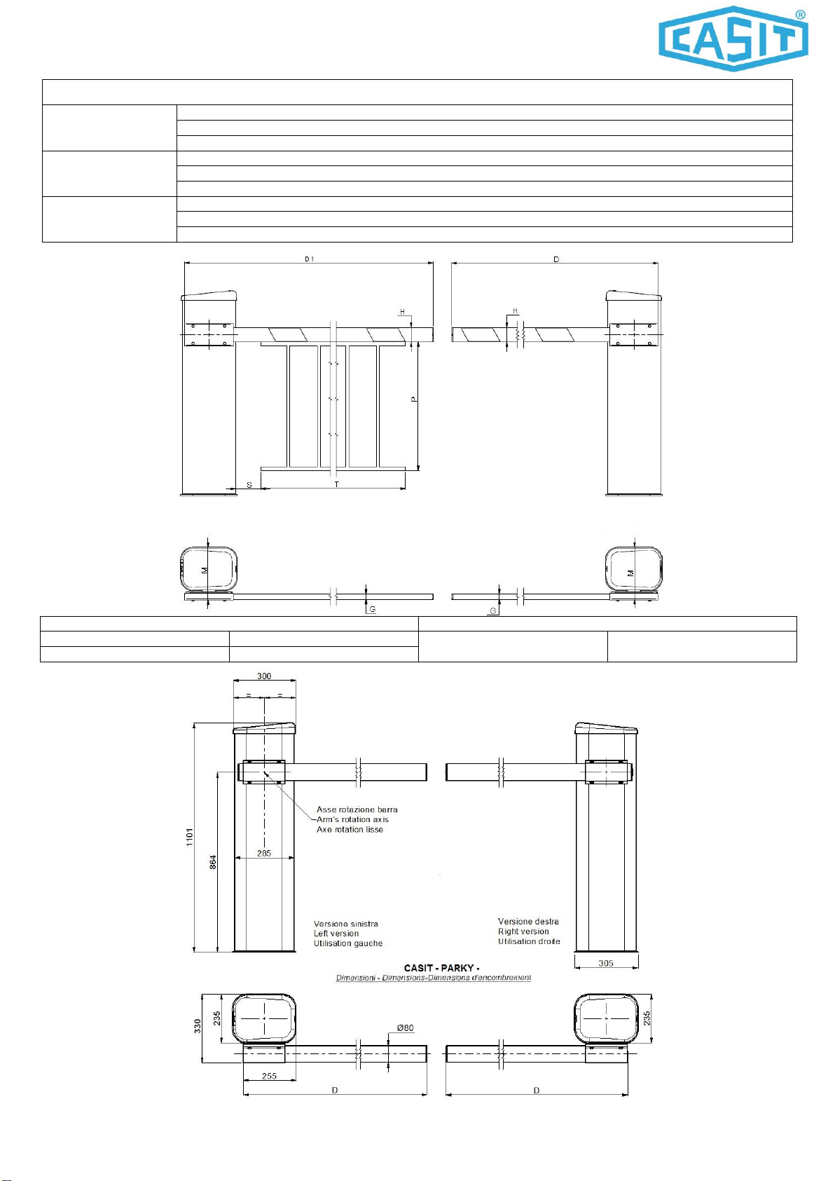
PARKY
Pagina 5 di 16 Rev. 02 del 11/05/2017
ENGLISH –DESCRIPTION COMPONENTS
Spring connection on cabinet
Spring connection on lever arm
Adjustable stopper for lever arm
Cover of shaft for manual release
FRANCAIS –DESCRIPTION des PARTIES
Plaque de fixation de la lisse
Lien de resort sur bras du levier
Butèe registrable pour bras du levier
Fin de course ouvre/ferme
Actionneurs de fin de course
Arbre deverrouillage motoreducteur
Motoreducteur avec encodeur
Couvercle arbre de deverrouillage
1 - INSTALLAZIONE E MESSA IN FUNZIONE
1 - INSTALLATION MISE EN FONCTION
1.0-Verificare la conformità della barra e degli articoli a corredo.
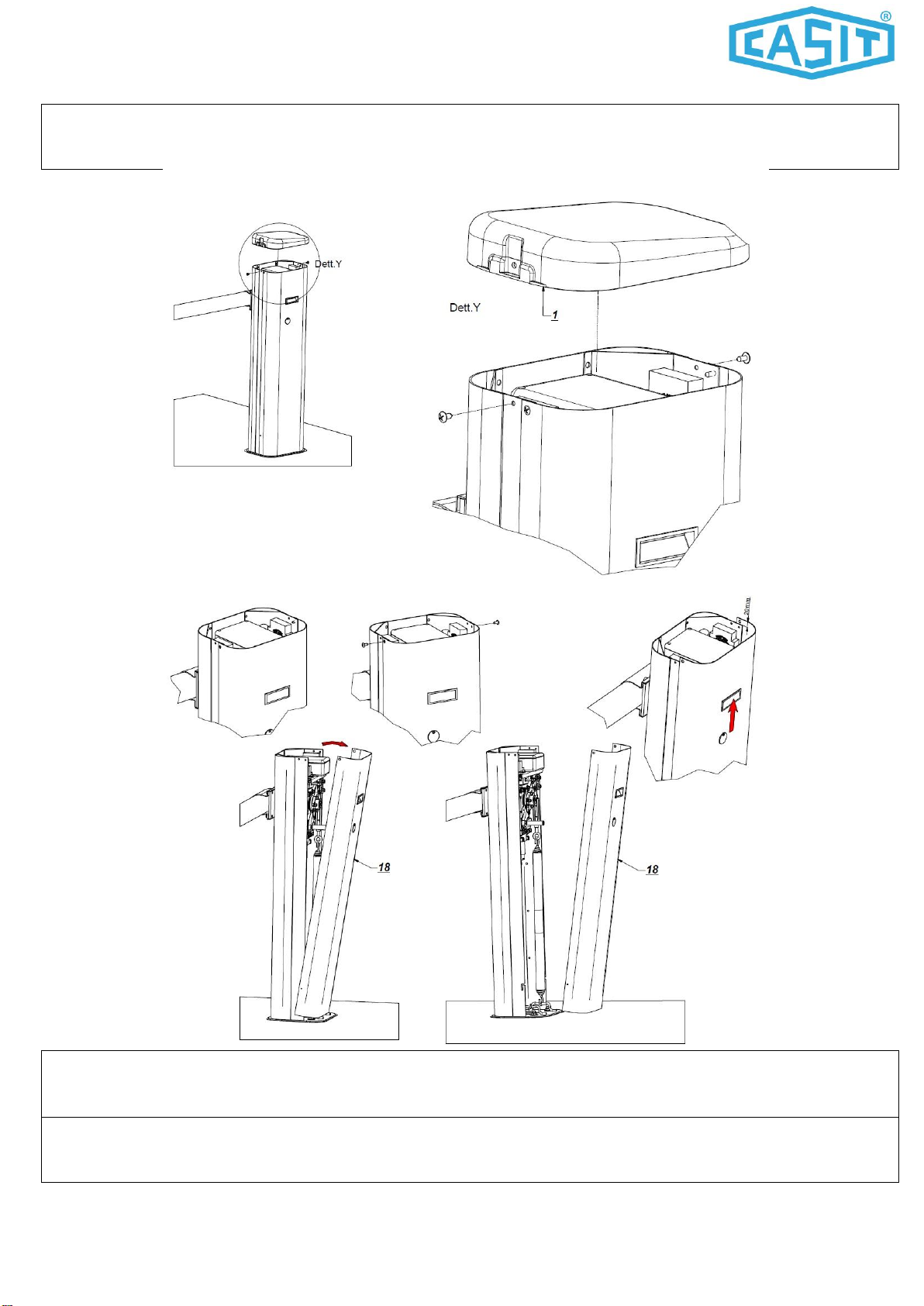
Atttenzione : il copri-attacco asta(part.4) è imballato e fissato con fastex agli attacchi molle su armadio(part.11)
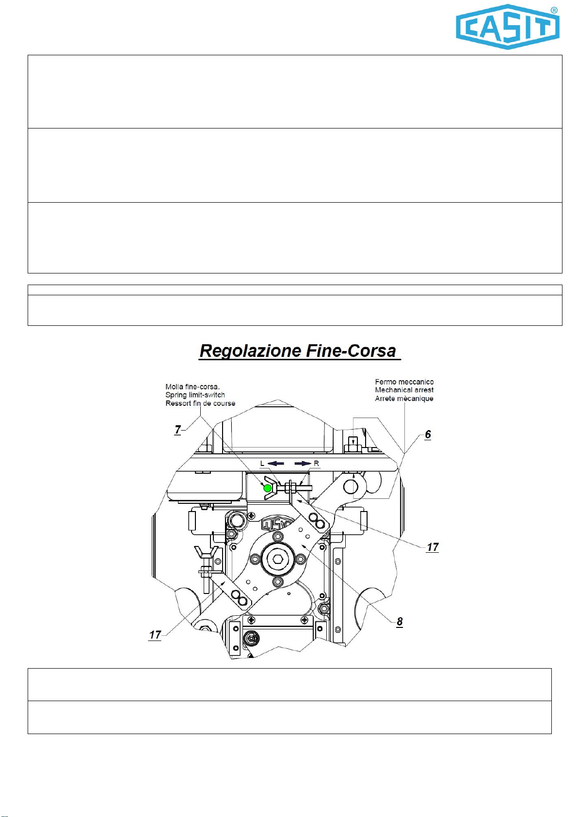
La versione standard Casit è DESTRA(fig.1.0): piastra albero motore(part.2) e molle ( part.13) in posizione verticale - braccio
leva(part.8) con estremità lato molle a ore 7 - estremità lato arresto meccanico a ore 1.
Se è necessario trasformare la barra destra in sinistra :braccio leva(part.8) con estremità lato molle a ore 5 - estremità lato
arresto meccanico a ore 11, procedere come segue.
1.Misurare ed annotare la misura X del registro molle(part.14)
2.Smontare le molle di bilanciamento(part.13), il registro per molle(part.14), l’attacco molle(part.15).
3.Montare le n.4 viti M6X20 uni5931 che bloccano il braccio leva(part.8).
4.Ruotare di 90 gradi in senso orario il braccio leva(part.8) e bloccarlo con le n.4 viti M6x20 uni5931 nella nuova posizione.
5.Montare le molle di bilanciamento(part.13), il registro per molle(part.14), l’attacco molle(part.15) sul lato del braccio leva a ore 5.
6.Regolare il registro molle sulla quota X rilevata al punto 1.
7.Verificare il corretto collegamento e funzionamento del finecorsa elettrico(part.7).Se occorre regolare i part.17 e 6.
1.0-Check conformity of the barrier and the accessories supplied.
Warning : the boom attachment cover(part.4) is packed and fixed with fastex to the spring connection on
cabinet(part.11)
The standard version Casit is RIGHT(fig.1.0) : motor-shaft plate(pert.2) and springs(part.13) in vertical position –lever
arm(part.8) side spring oriented at 7 o’clock, side mechanical stopper oriented at 1 o’clock.
If you need change the right version in left version : lever arm(part.8) side spring oriented at 5 o’clock, side mechanical
stopper oriented at 11 o’clock.
1.Measure and note the X measure of spring adjuster(part.14)
2.Dissassemble springs(part.13), spring adjuster(part.14), spring connection on lever arm(part.15).
3.Dissasemble the n.4 screws M6x20 uni5931 that fixe the lever arm(part.8).
4.Turm lever arm (part.8) 90 degrees clockwise and fix it in new position with the n.4 screws M6x20 uni5931
5.Assemble springs(part.13), spring adjuster(part.14), spring connection on lever arm(side oriented at 5 o’clock).
6.Adjust the spring adjuster to X measure detected to point 1.
7.Check the correct electric wiring and working of limit switch(part.7).If you need adjust part 17 and part.6