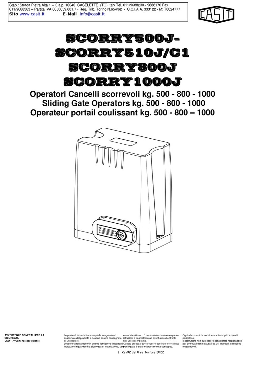
Casit ROLLY MC300/RC Instruction Manual

ISO 9001:2015
Cert. n. 3614/5
Quality System Certified
Cancelli Automatici Shed Infissi Telecomandati MADE IN ITALY
Pagina 1 di 11 Rev. 05 del 09/11/2019
Stab.: Strada Pietra Alta 1 – C.a.p. 10040 CASELETTE (TO) Italy
Tel. +39 011 9688230–170 Fax +39 011 9688363
Partita IVA 0050659.001.7 Reg. Trib. Torino N.654/62
C.C.I.A.A. 333122 - M: T0024777 Web: www.casit-italy.com
Email: info@casit.it Email pec: dir[email protected]
ROLLY
MC300/R MC300/RC MC300/RCM
MANUALE DI INSTALLAZIONE
MANUTENZIONE E CATALOGO
RICAMBI / ACCESSORI
INSTAL
LATION AND MAINTENANCE
MANUAL AND SPARE PARTS /
ACCESSORIES CATALOGUE
MANUEL D’INSTALLATION ET
D’ENTRETIEN ET CATALOGUE DES
RECHANGES / ACCESSOIRES
OPERATORE(MOTORUOTA) PER
CANCELLI A BATTENTE
OPARATOR(MOTOR WHEEL) FOR THE
AUTOMATION OF SWING GATES
OPERATOR(ROUE MOTORIZE’) ÉTUDIÉ
POUR L’AUTOMATISATION DE
PORTILLONS À BATTANTS
Apparecchio adatto al comando elettromeccanico di cancelli ad anta
battente con pavimento in piano o in leggera pendenza.
Riduttore, CASIT 33/C, con motore trifase o monofase con condensatore.
Può essere installato su cancelli di ogni dimensione purché autoportanti.
La rotazione avviene tramite ruota gommata intercambiabile.
In caso di mancanza di corrente si solleva il gruppo tramite apposita
maniglia e si comanda direttamente il cancello.
L’apparecchio è predisposto, corredato di apposita centrale
elettronica, per l'abbinamento a tutti i dispositivo di protezione previsti dalle
Norme vigenti.
L’operatore è autobloccante, ma per garantire la chiusura del cancello è
necessario montare l’elettroserratura in quanto la ruota potrebbe slittare
sulla pavimentazione.
L’arresto del motore avviene a mezzo dei finecorsa è quindi possibile aprire
anche a 360 gradi se la centrale lo permette come temporizzazione.
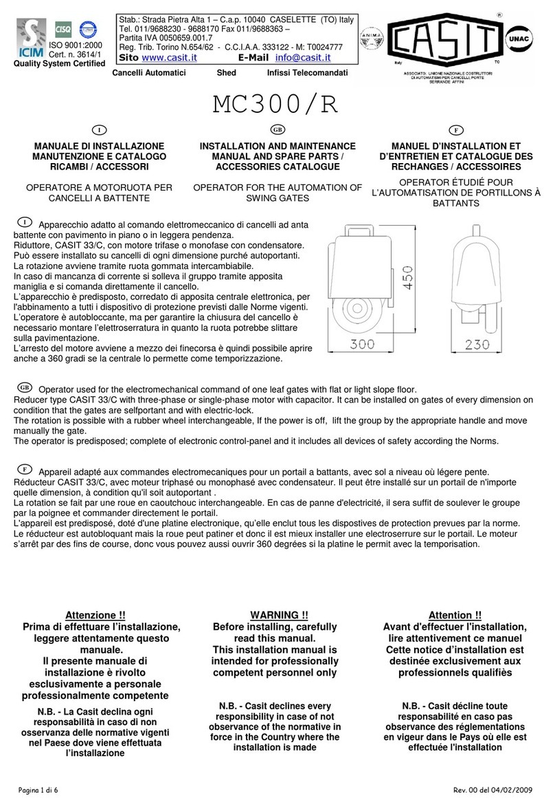
Operator used for the electromechanical command of one leaf gates with flat or light slope floor.
Reducer type CASIT 33/C with three-phase or single-phase motor with capacitor. It can be installed on gates of every dimension on
condition that the gates are selfportant and with electric-lock.
The rotation is possible with a rubber wheel interchangeable, If the power is off, lift the group by the appropriate handle and move
manually the gate.
The operator is predisposed; complete of electronic control-panel and it includes all devices of safety according the Norms.
Appareil adapté aux commandes electromecaniques pour un portail a battants, avec sol a niveau où légere pente.
Réducteur CASIT 33/C, avec moteur triphasé ou monophasé avec condensateur. Il peut être installé sur un portail de n'importe
quelle dimension, à condition qu'il soit autoportant .
La rotation se fait par une roue en caoutchouc interchangeable. En cas de panne d'electricité, il sera suffit de soulever le groupe
par la poignee et commander directement le portail.
L'appareil est predisposé, doté d'une platine electronique, qu’elle enclut tous les dispostives de protection prevues par la norme.
Le réducteur est autobloquant mais la roue peut patiner et donc il est mieux installer une electroserrure sur le portail. Le moteur
s’arrêt par des fins de course, donc vous pouvez aussi ouvrir 360 degrées si la platine le permit avec la temporisation.
Attenzione !!
Prima di effettuare l’installazione,
leggere attentamente questo
manuale.
Il presente manuale di
installazione è rivolto
esclusivamente a personale
professionalmente competente
N.B. - La Casit declina ogni
responsabilità in caso di non
osservanza delle normative vigenti
nel Paese dove viene effettuata
l’installazione
WARNING !!
Before installing, carefully
read this manual.
This installation manual is
intended for professionally
competent personnel only
N.B. - Casit declines every
responsibility in case of not
observance of the normative in
force in the Country where the
installation is made
Attention !!
Avant d'effectuer l'installation,
lire attentivement ce manuel
Cette notice d’installation est
destinée exclusivement aux
professionnels qualifiès
N.B. - Casit décline toute
responsabilité en caso pas
observance des réglementations
en vigeur dans le Pays où elle est
effectuée l'installation
GB
I
F
I
GB
F

MC300/R ROLLY
Pagina 2 di 11 Rev. 06 del 23/05/2023
1. AVVERTENZE GENERALI PER LA SICUREZZA
USO – Avvertenze per l’utente
Le presenti avvertenze sono parte integrante ed essenziale del
prodotto e devono essere consegnate all’utilizzatore.
Leggerle attentamente in quanto forniscono importanti
indicazioni riguardanti la sicurezza di installazione, uso e
manutenzione. È necessario conservare queste istruzioni e
trasmetterle ad eventuali subentranti nell’uso dell’impianto.
Questo prodotto dovrà essere destinato solo all’uso per il quale
è stato espressamente concepito.
Ogni altro uso è da considerarsi improprio e quindi pericoloso.
Il costruttore non può essere considerato responsabile per
eventuali danni causati da usi impropri, erronei ed irragionevoli.
Evitare di operare in prossimità delle cerniere o organi
meccanici in movimento. Non entrare nel raggio di azione
della porta o cancello motorizzati mentre è in movimento.
Non opporsi al moto della porta o cancello motorizzati poiché
può causare situazioni di pericolo. Non permettere ai bambini
di giocare o sostare nel raggio di azione della porta o cancello
motorizzati. Tenere fuori dalla portata dei bambini i
radiocomandi e/o qualsiasi altro dispositivo di comando, per
evitare che la porta o cancello motorizzati possa essere
azionata involontariamente. In caso di guasto o di cattivo
funzionamento del prodotto, disinserire l’interruttore di
alimentazione, astenendosi da qualsiasi tentativo di riparazione
o di intervento diretto e rivolgersi solo a personale
professionalmente competente. Il mancato rispetto di quanto
sopra può creare situazioni di pericolo.
L’utente può solo eseguire la manovra manuale.
Qualsiasi intervento di pulizia, manutenzione o riparazione,
deve essere effettuato da personale professionalmente
competente.
Per garantire l’efficienza dell’impianto ed il suo corretto
funzionamento è indispensabile attenersi alle indicazioni del
costruttore facendo effettuare da personale professionalmente
competente la manutenzione periodica della porta o cancello
motorizzati.
In particolare si raccomanda la verifica periodica del corretto
funzionamento di tutti i dispositivi di sicurezza.
Gli interventi di installazione, manutenzione e riparazione
devono essere documentati e tenuti a disposizione
dell’utilizzatore.
INSTALLAZIONE – Istruzioni per l’installatore
L’installazione deve essere eseguita da personale
professionalmente competente. L’installazione, i collegamenti
elettrici e le regolazioni devono essere effettuati nell’osservanza
della Buona Tecnica e in ottemperanza alle norme vigenti.
Leggere attentamente le istruzioni prima di iniziare
l’installazione del prodotto. Una errata installazione può essere
fonte di pericolo.
I materiali dell’imballaggio (plastica, polistirolo, ecc.) non vanno
dispersi nell’ambiente e non devono essere lasciati alla portata
dei bambini in quanto potenziali fonti di pericolo.
Prima di iniziare l’installazione verificare l’integrità del prodotto.
Non installare il prodotto in ambiente e atmosfera esplosivi:
presenza di gas o fumi infiammabili costituiscono un grave
pericolo per la sicurezza.
Prima di installare la motorizzazione, apportare tutte le
modifiche strutturali relative alla realizzazione dei franchi di
sicurezza ed alla protezione o segregazione di tutte le zone di
schiacciamento, cesoiamento, convogliamento e di pericolo in
genere. Verificare che la struttura esistente abbia i necessari
requisiti di robustezza e stabilità.
Il costruttore della motorizzazione non è responsabile
dell’inosservanza della Buona Tecnica nella costruzione degli
infissi da motorizzare, nonché delle deformazioni che
dovessero intervenire nell’utilizzo.
I dispositivi di sicurezza (fotocellule, coste sensibili, stop di
emergenza,ecc.) devono essere installati tenendo in
considerazione: le normative e le direttive in vigore, i criteri della
Buona Tecnica, l’ambiente di installazione, la logica di
funzionamento del sistema e le forze sviluppate dalla porta o
cancello motorizzati. I dispositivi di sicurezza devono
proteggere eventuali zone di schiacciamento, cesoiamento,
convogliamento e di pericolo in genere, della porta o cancello
motorizzati.
Applicare le segnalazioni previste dalle norme vigenti per
individuare le zone pericolose. Ogni installazione deve riportare
in modo visibile l’indicazione dei dati identificativi della porta o
cancello motorizzati.
Prima di collegare l’alimentazione elettrica accertarsi che i dati
di targa siano rispondenti a quelli della rete di distribuzione
elettrica.
Prevedere sulla rete di alimentazione un
interruttore/sezionatore onnipolare con distanza d’apertura dei
contatti uguale o superiore a 3 mm.
Verificare che a monte dell’impianto elettrico vi siano un
interruttore differenziale e una protezione di sovracorrente
adeguati.
Collegare la porta o cancello motorizzati a un’efficace impianto
di messa a terra eseguito come previsto dalle vigenti norme di
sicurezza.
Il costruttore della motorizzazione declina ogni responsabilità
qualora vengano installati componenti incompatibili ai fini della
sicurezza e del buon funzionamento. Per l’eventuale
riparazione o sostituzione dei prodotti dovranno essere utilizzati
esclusivamente ricambi originali.
L’installatore deve fornire tutte le informazioni relative
al funzionamento automatico, manuale e di emergenza
della porta o cancello motorizzati, è consegnare
all’utilizzatore dell’impianto le istruzioni d’uso.
1. GENERAL SAFETY PRECAUTIONS
USE – Warnings for the User
The following precautions are an integral and essential
part of the products and must be supplied to the user.
Read them carefully as they contain important indications
for the safe installation, use and maintenance.
These instructions must be kept and forwarded to all
possible future user of the system.
This product must be used only for that which it has been
expressely designed. Any other use is to be considered
improper and therefore dangerous.
The manufacturer cannot be held responsible for possible
damage caused by improper, erroneous or unreasonable
use. Avoid operating in the proximity of the hinges or
moving mechanical parts.
Do not enter the field of action of the motorised door or
gate while in motion.
Do not obstruct the motion of the motorised door or gate
as this may cause a situation of danger.
Do not allow children to play or stay within the field of
action of the motorised door or gate. Keep remote control
or any other control devices out of the reach of children,
in order to avoid possible involuntary activation of the
motorised door or gate.
In case of breakdown or malfunctioning of the product,
disconnect from the mains, do not attempt to repair or
intervene directly and contact only qualified personnel.
Failure to comply with the above may create a situation of
danger.
The user can only execute the manual drive.
All cleaning, maintenance or repair work must be carried
out by qualified personnel.
In order to guarantee that the system works efficiently
and correctly it is indispensable to comply with the
manufacturer’s indications thus having the periodic
maintenance of the motorised door or gate carried out by
qualified personnel.
In particular regular checks are recommended in order to
verify that the safety devices are operating correctly.
All installation, maintenance and repair work must be
documented and made available to the user.
INSTALLATION – Instructions for the fitter
The installation must be carried out by qualified
personnel. The installation, the electrical connections and
the settings must be completed in conformity with good
workmanship and with the laws in force. Read the
instructions carefully before beginning to instal the
product. Incorrect installation may be source of danger.
Packaging materials (plastic, polystyrene, etc.) must not
be allowed to litter the environment and must be kept out
of the reach of children for whom they may be a source of
danger.
Before beginning the installation check that the product is
in perfect condition. Do not install the product in explosive
areas and atmospheres: the presence of flammable gas
or fumes represents a serious threat to safety.
Before installing the motorisation device, make all the
structural modifications necessary in order to create
safety clearance and to guard or isolate all the
compression, shearing, trapping and general danger
areas. Check that the existing structure has the
necessary strength and stability.
The manufacturer of the motorisation device is not
responsible for the non-observance of workmanship in
the construction of the frames to be motorised, nor for
deformations that may occur during use.
The safety devices (photoelectric cells, mechanical
obstruction sensor, emergency stop, etc.) must be
installed taking into account: the provisions and the
directives in force, good workmanship criteria, the
installation area, the functional logic of the system and
the forces developed by the motorised door or gate.
The safety devices must protect against compression,
shearing, trapping and general danger areas of the
motorized door or gate.
Display the signs required by law to identify danger
areas. Each installation must bear a visible indication of
the data identifying the motorised door or gate.
Before connecting to the mains check that the rating is
correct for the destination power requirements. A
multipolar isolation switch minimum contact gaps of 3mm
must be included in the mains supply.
Check that upstream of the electrical installation there is
an adequate differential switch and a suitable circuit
breaker. Ensure that the motorised door or gate has an
earth terminal in accordance with the safety regulations in
force. The manufacturer of the motorising device
declines all responsibility in cases where components
which are incompatible with the safe and correct
operation of the product have been installed. For repairs
or replacement of products only original spare must be
used.
The fitter must supply all information concerning the
automatic, the manual and the emergency operation
of the motorised door or gate, and must provide the
user of the device with the operating instructions.
1. CONSIGNES GENERALES DE SECURITE
UTILISATION – Conseignes pour l’utilisateur
Ces consignes sont partie intégrante et essentielle du produit
et doivent être remises à l’utilisateur. Lire ces consignes
attentivement, car elles contiennent des instructions
concernant la sécurité de l’installation, de l’utilisation et de
l’entretien de ce système.
Il est indispensable de conserver ces instructions et de les
transmettre à d’autres utilisateurs éventuels de ce système.
Ce produit doit être destiné exclusivement à l’utilisation pour
laquelle il a été conçu. Toute autre utilisation est inappropriée
et par conséquent dangereuse.
Le constructeur ne peut être tenu pour responsable en cas
d’éventuels dommages causés par une utilisation
inappropriée, erronée et irrationnelle. Eviter de manoeuvrer à
proximité des charnières ou des organes mécaniques en
mouvement. Ne pas entrer dans le rayon d’action de la porte
ou du portail automatisés lorqu’ils sont en mouvement. Ne pas
s’opposer au mouvement de la porte ou du portail automatisés
car cela peut être source de danger.
Ne pas laisser des enfants jouer ou se tenir dans le rayon
d’action de la porte ou du portail automatisés.
Garder hors de la portée des enfants les radiocommandes
et/ou tout autre dispositif de commande, afin d’éviter que la
porte ou le portail automatisés puissent être actionnés
involontairement.
En cas de panne ou de mauvais fonctionnement du produit,
débrancher l’interrupteur de secteur et s’abstenir de toute
tentative de réparation ou d’intervention directe. S’adresser
uniquement à un professionnel compétent.
Le non-respect de ces instructions peut être cause de danger.
L'utilisateur peut seulement exécuter la dépannage
manuel.
Afin de garantir l’efficacité du système et son fonctionnement
correct, il est indispensable d’observer les instructions du
constructeur en s’adressant à un professionnel compétent
pour l’entretien périodique de la porte ou du portail
automatisés. Plus particulièrement, il est recommandé de
procéder à une vérification périodique du fonctionnement
correct de tous les dispositifs de sécurité.
Les interventions d’installation, d’entretien et de réparation
doivent être documentées et mises à la disposition de
l’utilisateur.
INSTALLATION – instructions pour l’installateur
L’installation doit être effectuée par un professionnel
compétent. L’installation, le raccordement électrique et les
réglages doivent être effectués selon règles de Bonne
Technique et respecter la réglementation en vigueur.
Lire attentivement les instructions avant de procéder à
l’installation du produit. Une installation erronée peut être
source de danger. Les materiaux de l’emballage (plastique,
polystyrène, etc.) ne doivent pas être abandonnés dans la
nature et ne doivent pas être laissés à la portée des enfants,
car ils sont une source potentielle de danger.
Avant de procéder à l’installation, vérifier l’intégrité du produit.
Ne pas installer le produit à proximité de matières explosives :
la présence de gaz ou de vapeurs inflammables représente un
grave danger pour la sécurité. Avant d’installer les
automatismes, apporter toutes les modifications structurelles
relatives à la realisation des distances de sécurité et à la
protection ou ségrégation de toutes les zones d’écrasement,
de cisaillement, d’entraînement et de danger en général.
Vérifier que la structure existante ait les qualités requises de
robustesse et de stabilité. Le constructeur des automatismes
n’est pas responsable du non-respect des règles de Bonne
Technique dans la construction des châssis devant être
équipés d’automatismes, ni des déformations que pourrait
entraîner l’utilisation du produit.
Le dispositifs de sécurité (photocellules, barres palpeuses,
arrêt d’urgence, etc.) doivent être installés en tenant compte
des normes et directives en vigueur, des critères de Bonne
Technicque, de l’emplacement de l’installation, de la logique
de fonctionnement du système et des forces dégagées par la
porte ou le portail équipes d’automatismes.
Les dispositifs de sécurité doivent protéger les zones
éventuelles d’écrasement, de cisaillement, d’entraînement et
de danger en général, de la porte ou du portail automatisés.
Appliquer la signalisation prévue par la réglementation en
vigueur pour localiser les zones dangereuses.
Toute installation doit indiquer de façon visible les données
d’identification de la porte ou du portail automatisés.
Avant de procéder au raccordement électrique, s’assurer que
les données de la plaquette signalétique correspondent à
celles du réseau d’alimentation électrique. Prévoir sur le
réseau d’alimentation un dispositif de coupure omnipolaire
avec une distance d’ouverture des contacts égale ou
supérieure à 3mm. Vérifier qu’en amont de l’installation
électrique il y ait un interrupteur différentiel ainsi qu’une
protection contre des surcharges de courant adéquate.
Relier la porte ou le portail automatisés à un système de mise
à la terre efficace installé conformément aux normes de
sécurité en vigueur. Le constructeur des automatismes
décline toute responsabilité au cas où seraient installés des
composants incompatibles en termes de sécurité et de bon
fonctionnement. En cas de réparation ou de remplacement
des produits, des pièces de rechange originales
impérativement être utilisées.
L’installateur doit fournir tous les renseignements
concernant le fonctionnement automatique, manuel
ou de secours de la porte ou du portail automatisés
et remettre la notice d’emploi à l’utilisateur.
F
GB
I

MC300/R ROLLY
Pagina 3 di 11 Rev. 06 del 23/05/2023
CARATTERISTICHE TECNICHE
–
TECHNICAL DATA
–
DONNES TECNIQUES
Modelli
Models
Modèles
Alimentazione
Power supply
Alimentation
Potenza/
Condensatore
Power/
Capacitor
Puissance/
Condensateur
Coppia
Torque
Couple
Spinta della
ruota
Push of the
wheel
Pousseè de
la roue
Larghezza max
porta
Max lenght
door
Largeur
maximum porte
Peso max porta
Max weight door
Poid maximum
de la porte
Velocità
Speed
Vitesse
%
USE
MC300/R63MD MS
MC300/RC63MD MS
MC300/RCM63MD MS
230Vac
50/60Hz
Monofase
Singlephase
Monophase
300 W
2,5 A
30 Mf
standard
22 Nm 20 kg 5,00 mt 500 kg
16 mt/1’
50%
460 W
2,0 A
16 Mf
optional
40 Nm 35 kg 6,00 mt 600 kg
MC300/R80MD MS
MC300/RC80MD MS
MC300/RCM80MD MS
550 W
31,5 Mf 75 Nm 66 Kg
8,00 mt
1000 kg 60%
MC300/R71TD TS
MC300/RC71TD TS
MC300/RCM71TD TS
400Vac
50/60Hz
Trifase
Threephase
Triphase
370 W 60 Nm 53 kg 900 kg
80%
MC300/R80TD TS
MC300/RC80TD TS
MC300/RCM80TD TS
750 W 80 Nm 66 kg 1000 kg
MODELLI DISPONIBILI
–
AVAILABLE MODELS
-
MODÈLES DISPONIBLES
MC300/R
Operatore per pavimento in piano max dislivello 30 mm,
attacco oscillante
Operator for flat floor Max unevenness 30 mm, tilting connection
Operateur pour plancher en plan max dénivelle 30 mm, plaque de fixation oscillant
MC300/R63MD
MC300/R80MD
MC300/R71TD
MC300/R80
TD
(*)
Mod. Dx (Fig.1)
MC300/R63MS
MC300/R80MS
MC300/R71TS
MC300/R80
TS
(*)
Mod. Sx (Fig.1)
Motor mec63 1 phase Motor mec80 1 phase Motor mec71 3 phase Motor mec80 3 phase
MC300/RC
Operatore per pavimento in pendenza max dislivello 350 mm,
attacco telescopico
Operator for slope floor Max unevenness 350 mm, telescopic connection
Operateur pour plancher en pente max dénivelle 350 mm, plaque de fixation télèscopique
MC300/RC63MD
MC300/RC80MD
MC300/RC71TD
MC300/RC
80
TD
(*)
Mod. Dx (Fig.1)
MC300/RC63MS
MC300/RC80MS
MC300/RC71TS
MC300/RC
80
TS
(*)
Mod. Sx (Fig.1)
Motor mec63 1 phase Motor mec80 1 phase Motor mec71 3 phase Motor mec80 3 phase
MC300/RCM
Operatore per pavimento in piano max dislivello 30 mm,
attacco telescopico con moll
a di pressione
(per aumentare l’aderenza al pavimento)
Operator for flat floor Max unevenness 30 mm, telescopic connection with spring
(in order to increase the grip to the ground)
Operateur pour plancher en plan max dénivelle 30 mm, plaque de fixation télèscopique avec ressort du pression
(pour agumenter l’adhérence au plancher)
MC300/RC63MD
MC300/RC80MD
MC300/RC71TD
MC300/RC
80
TD
(*)
Mod. Dx (Fig.1)
MC300/RC63MS
MC300/RC80MS
MC300/RC71TS
MC300/RC
80
TS
(*)
Mod. Sx (Fig.1)
Motor mec63 1 phase Motor mec80 1 phase Motor mec71 3 phase Motor mec80 3 phase
Specificare all’ordine tens i one m o t o r e (m o nofas e o tri fase).
Spe c i f y o n t he order the type o f m o t o r (singlephase o r t h r eephase).
Signal e r à la com m an de le typ e d u m ot e u r (m onopha se o trip has e ) .
(* ) S u ric h i es ta – On demand – Sur de m and e
Fig.1

MC300/R ROLLY
Pagina 4 di 11 Rev. 06 del 23/05/2023
POSA IN OPERA MC300/R
(attacco oscillante)
Il gruppo viene fissato al cancello
saldando l'apposita contropiastra
(FIG.2) in modo che la posizione dello
stesso risulti circa a 1/10 della luce.
La posizione dei finecorsa (chiusura e
apertura) e relativi pattini riportati nelle
figure 2-3-4-5 è indicativa e dovrà
essere prevista di volta in volta
dall'installatore in relazione al tipo di
serramento e alla muratura.
INSTALLATION MC300/R
(tilting connection)
To fix the group it weld its on the
bracket predisposed (FIG. 2) in way
that the its position result about 1/10 of
the light.
The position of the limit-switch (FC
close and FA open) and relative
brackets intervention (P-FC close and
P-FA open) see in the designs 2-3-4-5
is indicative and will must be
calculated of the technician in relation
at the type of gate.
POSE MC300/R
(plaque de fixation oscillant)
Le groupe est fixé au portail soudant la
contre-plaque de facon que sa position
soit a 1/10 de la largeur du portail.
La position des fins de course
(ouverture et fermeture ) et les patins
relativs figure 2-3-4-5 sont indicatifs et
devront être prevus a chaque fois par
l'installateur en relation avec le type de
scellement et de maconnerie.
I
GB
F

MC300/R ROLLY
Pagina 5 di 11 Rev. 06 del 23/05/2023
POSA IN OPERA MC300/RC
(attacco telescopico)
ATTENZIONE: rispettare le misure
570 max / 220 min
I criteri di posa sono uguali a quelli
del gruppo MC300/R con l’aggiunta
di una barra direzionale (FIG 3).
INSTALLATION MC300/RC
(telescopic system)
WARNING: Respect the quotes
570 max / 220 min
For installation of the group see
instructions of the MC300/R with
addition of a directional bar (FIG 3).
POSE MC300/RC
(plaque de fixation
telescopique)
ATTENTION : Respecter les
measures 570 max / 220 min
Les criters de pose sont identiques a
ceux du groupe MC300/R avec en
plus une barre de direction (FIG 3).
I
GB
F

MC300/R ROLLY
Pagina 6 di 11 Rev. 06 del 23/05/2023
POSA IN OPERA MC300/RCM
(attacco telescopico con molla di
pressione)
ATTENZIONE: rispettare le misure
270 max / 240 min(corsa 30)
Applicazione speciale corredato di
molla per aumentare l’aderenza al
pavimento.
I criteri di posa sono uguali a quelli
del gruppo MC300/R con l’aggiunta
di una barra direzionale (FIG 4).
INSTALLATION MC300/RCM
(telescopic system with
spring)
WARNING: Respect the quotes
270 max / 240 min(stroke 30)
Special application of the group to
addition of soft at the group for a
more grip at the floor. For installation
of the group see instructions of the
MC300/R with addition of a
directional bar (FIG 4).
POSE MC300/RCM
(plaque de fixation
telescopique avec ressort)
ATTENTION: Respecter les
measures 270 max / 240 min
(course 30)
Application speciale du groupe doté
d'un ressort pour augmenter
l'adherence au sol.
Les criters de pose sont identiques a
ceux du groupe MC300/R avec en
plus une barre de direction (FIG 4).
I
GB
F

MC300/R ROLLY
Pagina 7 di 11 Rev. 06 del 23/05/2023
MC300/R63MD MS
-
MC300/RC63MD MS
-
MC300/RCM63MD MS
COLLEGAMENTO ELETTRICO DEL MOTORE - MOTOR ELECTRICAL CONNECTION - BRANCHEMENT ELECTRIQUE MOTEUR
COLLEGAMENTO ELETTRICO DEL MOT
ORE ( vedi etichetta AF123F1 applicata sul motore e sopra riprodotta)
:
1-Smontare il coprimorsettiera
2-Collegare comune a ROSSO COMUNE
3-Collergare Fase 1 e Fase 2 a MARRONE e BLU.
4-Collegare il filo di terra direttamente sulla carcassa motore sull’attacco predisposto.
5-Collegare T1 e T2( protettore termico del motore) allo STOP della centrale elettronica.
N.B. Nel caso che il senso di rotazione non sia quello voluto, invertire i fili 1-2 della fase. Condensatore colegato da
Casit a fasi 1 e 2.
ATTENZIONE: Se T1 e T2 non sono collegati allo STOP della centrale il motore brucia.
MOTOR ELECTRICAL CONNECTION (see AF123F1 label applied to the motor and reproduced above)
:
1-Remove the terminal block cover
2-Connect the commo phase to RED COMUNE
3-Connect the two phases 1-2 to BROWN and BLUE.
4-Connect the earth wire directly to the motor casing on the prearranged attachment.
5-Connect T1 and T2 (motor thermal protector) to the electronic control unit STOP.
N.B. If the direction of rotation is not the desired one, invert wires 1-2 of the phase. Capacitor connected by Casit to phases 1 and 2
.
WARNING: If T1 and T2 are not connected to the STOP of the control unit, the motor burns
BRANCHEMENT ELECTRIQUE MOTEUR (voir étiquette AF123F1 apposée sur le moteur e
t reproduite ci
-
dessus)
:
1-Retirer le couvercle du bornier
2-Raccorder la commune à la COMUNE ROUGE
3-Connectez les deux phases 1-2 à MARRON et BLEU.
4-Connecter le fil de terre directement sur la carcasse du moteur sur le raccordement prédisposé.
5-Connecter T1 et T2 (protecteur thermique moteur) à la centrale électronique STOP.
N.B. Si le sens de rotation n'est pas celui souhaité, inverser les fils 1-2 de la phase. Condensateur connecté par Casit aux phases 1 et
2.
ATTENTION : si T1 et T2 ne sont pas branchès au STOP de la centrale, le moteur brule.

MC300/R ROLLY
Pagina 8 di 11 Rev. 06 del 23/05/2023
MC300/R
-
RC
Limiti di impiego – angolazione moto ruota
Limits of use – motor wheel angle
Limites d'utilisation - angle du roue motorisè
1.La porta deve essere autoportante. Le cerniere ed il pilastro devono essere dimensionati per sostenere tutto il peso della porta.
Evitare ruote aggiuntiva, con funzione di aiuto per il peso della porta: genera attriti che pregiudicano il funzionamento della moto
ruota ed usura precoce ed anomalo della ruota
2.La forza di spinta per muovere la porta, applicata ove andrà posizionata moto ruota è max 15 kg.
3.Il pavimento deve garantire un ottimo attrito alla ruota per evitare slittamenti della ruota. In caso contrario prevedere pista in
materiale ad alto coefficiente di attrito.
4.Il pavimento deve avere una buona resistenza alla usura onde evitare che la ruota, con l’uso, lo consumi. In caso contrario
prevedere pista in materiale ad alta resistenza.
5. La motoruota va montata con un angolazione da min 3° a max 8° rispetto all’anta. Per evitare usura precoce ed anomalo della
ruota
Attenzione: La forma( cancello cieco),le dimension, il peso del cancello e le condizioni climatiche(es: vento forte) possono ridurre
anche notevolmente le prestazioni ed i limiti d’impiego dell’operatore.
1. The door must be self-supporting. The hinges and the pillar must be sized to support all the weight of the door. Avoiding the
additional wheel, which helps the weight of the door: it generates frictions that affect the operation of the motor wheel and early and
anomalous wheel wear
2.The pushing force to move the door, applied where it will be positioned motor wheel is max 15 kg.
3.The floor must guarantee excellent friction to the wheel to avoid wheel skid. Otherwise, provide a track with a high friction
coefficient material.
4.The floor must have a good resistance to wear to prevent the wheel from using it. Otherwise, provide a track made of high-
strength material.
5. The motor must be mounted with an angle of min. 3 ° to max 8 ° with respect to the door. To avoid premature and abnormal wear
of the wheel
Warning: The shape (blind gate), the dimensions, the weight of the gate and the climatic conditions (eg: strong wind) can also
considerably reduce the performance and the limits of use of the operator.
1. La porte doit être autoportante. Les charnières et le pilier doivent être dimensionnés pour supporter tout le poid de la porte. Eviter
la roue supplémentaire, ce qui aide le poids de la porte: cela génère des frictions qui affectent le fonctionnement de la roue et
l'usure précoce et anormale de roue
2.La force de poussée pour déplacer la porte, appliquée là où elle sera positionnée la roue motorisè, est de 15 kg maximum.
3.Le sol doit garantir un excellent frottement à la roue, pour éviter le patinage de la roue. Sinon, fournir une piste avec un matériau à
coefficient de friction élevé.
4.Le sol doit avoir une bonne résistance à l'usure pour empêcher la roue de l'utiliser. Sinon, fournissez une piste en matériau haute
résistance.
5. Le moteur doit être monté à un angle de 3 ° à 8 ° maximum par rapport au vantail. Pour éviter l'usure prématurée et anormale de
la roue
Attention: La forme (portail aveugle), les dimensions, le poids du portail et les conditions climatiques (par exemple: vent fort)
peuvent également réduire considérablement les performances et les limites d'utilisation de l'opérateur.

MC300/R ROLLY
Pagina 9 di 11 Rev. 06 del 23/05/2023
FIG.5 SCHEMA INDICATIVO POSA FINECORSA, PATTINI FINECORSA E DISPOSITIVI DI PROTEZIONE
FIG.5 SCHEME OF INSTALLATION OF SAFETY-DEVICE
FIG.5 SCHEMA INDICATIF POUR POSE DE FIN DE COURSE-PATIN DE FIN DE COURSE
ET DISPOSITIVES DE PROTECTION
FA. LIMIT SWITCH OPEN
FC. LIMIT SWITCH CLOSE
P-FA. BRACKET LIMIT SWITCH OPEN
P-FC. BRACKET LIMIT SWITCH CLOSE
CS2. SAFETY EDGES
CE-E. PHOTOCELL EXTERNAL
CE-I. PHOTOCELL INTERNAL
AR. STOPPER
FA. FIN DE COURSE OUVERTURE
FC. FIN DE COURSE FERMETURE
P-FA. PATIN FIN DE COURSE OUVERTURE
P-FC. PATIN FIN DE COURSE FERMETURE
CS2. BARRE PALPEUSE
CE-E. PHOTOCELLULES EXTERNES
CE-I. PHOTOCELLULES INTERNES
AR. BUTEES D'ARRET
FA. FINECORSA APERTURA
FC. FINECORSA CHIUSURA
P-FA. PATTINO FINECORSA APERTURA
P.FC. PATTINO FINECORSA CHIUSURA
CS2. COSTOLE PROTEZIONE
CE-E. FOTOCELLULE ESTERNE
CE-I. FOTOCELLULE INTERNE
AR. ARRESTO MECCANICO

MC300/R ROLLY
Pagina 10 di 11 Rev. 06 del 23/05/2023
MC300/R
-
RC
-
RCM
Procedura per azionamento manuale
Procedure for manual operation(manual release)
Procédure de fonctionnement manuel( deverrouillage)
L’operatore MC300/R-RC-RCM basa il suo funzionamento elettrico sul contatto della ruota al suolo. Per comandare
manualmente la porta occorre pertanto distanziare la ruota dal suolo.
Per tutte le versioni(R-RC-RCM) la prima operazione è sbloccare la elettro serratura.
In seguito:
Per la versione MC300/R, ruotare l’operatore sul perno del attacco oscillante che lo fissa alla porta, come segue: impugnare la
maniglia posta sulla copertura in plastica ed allo stesso tempo spingere dal basso verso l’alto l’operatore per farlo ruotare sul
perno di fissaggio alla porta di un angolo sufficiente ad allontanare la ruota dal suolo. Bloccare al cancello l’operatore, tramite
una cinghia o fune, per facilitare l’aperura/chiusura a mani della porta.
Per le versioni MC300/RC e RCM avvitare il volantino in plastica nera posto sul filettato fuoriuscente dal sistema di escursione,
finchè la ruota non è più a contatto con il suolo.
The MC300/R-RC-RCM operator bases its electrical operation on the contact of the wheel on the ground. To manually control
the door, the wheel must therefore be spaced from the ground.
For all versions (R-RC-RCM) the first operation is to unlock the electric lock.
Later:
For the MC300/R version,rotate the operator on the pivot of the swinging attachment that fixes it to the door, as follows: grasp
the handle on the plastic cover and at the same time push from the bottom at the same time push the operator from the bottom
to make him rotate on the fixing pin to the door of an angle sufficient to move the wheel away from the ground. Lock the operator
at the gate, by means of a strap or rope, to facilitate the opening / closing by hand of the door.
For the MC300/RC and RCM versions, screw the black plastic handwheel of the M10 thread of the suspension system until the
wheel is no longer in contact with the ground.
L'opérateur MC300/R-RC-RCM base son fonctionnement électrique sur le contact de la roue au sol. Pour contrôler
manuellement la porte, la roue doit donc être écartée du sol.
Pour toutes les versions (R-RC-RCM), la première opération consiste à déverrouiller la serrure électrique.
Plus tard::
Pour la version MC300/R, tournez l'opérateur sur le pivot de l'accessoire pivotant qui le fixe à la porte, comme suit: saisissez la
poignée sur le couvercle en plastique et poussez en même temps de bas en haut l'opérateur pour le faire tourner sur la goupille
de fixation à la porte d'un angle suffisant pour éloigner la roue du sol. Verrouiller l'opérateur à la porte, à l'aide d'une sangle ou
d'une corde, pour faciliter l'ouverture / fermeture à la main de la porte.
Pour les versions MC300/RC et RCM, vissez le volant en plastique noir du filetage M10 du système de suspension jusqu'à ce
que la roue ne soit plus en contact avec le sol.
MC300/R
MC300/RC
-
RCM

MC300/R ROLLY
Pagina 11 di 11 Rev. 06 del 23/05/2023
SMALTIMENTO – DISPOSAL – MISE AU REBUT
Al termine della vita dell’automazione,
assicuratevi che lo smantellamento sia
eseguito da personale qualificato e che i
materiali vengano riciclati o smaltiti
secondo le norme vigenti.
At the end of the life of the automatic
system, make sure that it is demolished
by qualified personnel and that the
materials are recycled or disposed as the
enforced norms
À la fin de la vie de l’automatisme,
assurez-vous que le démantèlement est
effectué par du personnel qualifié et que
les matériaux sont recyclés ou mis au
rebut en respectant les règles en vigeur.
LIMITI DELLA GARANZIA – TERMS OF WARRANTY – LIMITES DE LA GARANTIE
La garanzia è di 12 mesi decorrenti dalla
data di acquisto del prodotto ed è valida
solo per il primo acquirente.
Per garanzia si intende la sostituzione o
riparazione gratuita, delle parti
componenti l’apparecchiatura che
risultino difettose all’origine per vizi di
fabbricazione.
Essa decade in caso di: negligenza,
errore o cattivo uso del prodotto, uso di
accessori non conformi alle specifiche
del costruttore, manomissioni operate dal
cliente o da terzi, cause naturali (fulmini,
alluvioni, incendi, ecc.), sommosse, atti
vandalici, modifiche delle condizioni
ambientali del luogo d’installazione, in
conseguenza della mancata osservanza
di tutte le prescrizioni indicate nel libretto
istruzioni o della mancata osservanza
della normativa vigente.
Sono esclusi dalla garanzia gli interventi
inerenti l’installazione, dell’allacciamento
agli impianti di alimentazione, nonché le
eventuali manutenzioni specificate nel
libretto istruzioni.
Non comprende inoltre, le parti soggette
ad usura (batterie, pile, lampadine, ecc.).
La restituzione alla ditta costruttrice del
prodotto da riparare deve avvenire in
porto franco.
La ditta costruttrice restituirà il prodotto
riparato al mittente in porto assegnato. In
caso contrario la merce verrà respinta al
ricevimento o trattenuta alla spedizione.
L’acquisto del prodotto implica la piena
accettazione di tutte le condizioni della
garanzia.
La ditta costruttrice declina ogni
responsabilità per eventuali danni che
possano, direttamente o indirettamente,
derivare a persone, cose ed animali, in
conseguenza della mancata osservanza
di tutte le prescrizioni indicate nel libretto
istruzioni o della mancata osservanza
della normativa vigente. In caso di
intervento a domicilio, nel periodo
coperto da garanzia, l’utente è tenuto a
corrispondere il “DIRITTO FISSO DI
CHIAMATA” per spese di trasferimento a
domicilio, in vigore dalla data di
intervento, più manodopera.
Per eventuali controversie il Foro
competente è quello relativo alla
residenza della casa costruttrice.
The warranty is 12 months starting from
the date of purchase of the product and it
is valid only for the first buyer.
This warranty covers the free
replacement or repair of parts making up
items showing defects in its manufacture.
The warranty will expire in the event of:
negligence, incorrect or improper use of
the product, use of accessories not
conforming to the manufacturer’s
specifications, tampering by the
customer or by third parties, natural
causes (lightning, flood, fire, etc.),
insurrection, acts of vandalism, changes
in environmental conditions of the
installation site, in consequence of the
missed observance of all the suitable
prescriptions in the book instructions or
of the missed observance of the actual
normative.
This warranty does not cover assistance
for connecting to the power supply, as
well as the possible maintenances
specified in the book instructions.In
addition, it does not cover parts subject
to wear (battery,light etc.).
If the product has to be returned to the
builder for repair, it must be sent postage
paid. To the builder will return the
repaired product to the sender COD.
Under any other circumstances, the
product will be refused upon receipt or
held at the time of shipment.
Purchase of this product implies full
acceptance of all of the terms of this
warranty.
To the builder declines all liability for any
damage that may be caused either
directly or indirectly to persons, property
and animals caused by the non-
observance of all the rules stated in the
instructions booklet or to the non-
observance of the standard.
For on-site assistance during the period
covered by warranty, the customers must
pay the “CALL-OUT FEE” for travel
expenses, applicable on the date of
assistance, plus labour.
Any disputes the competent Court is the
same of the residence of the
manufacturer.
La garantie est de 12 mois à partir de la
date d'achat du produit et il est seul
valide pour l'acheteur premier
On entend par garantie, le remplacement
ou la réparation gratuite, en nos ateliers
des composants défectueux dont
l’origine est un vice de fabrication.
La garantie déchoit en cas de:
négligence, erreur ou mauvaise emploie
de produit, emploie d'accessoires pas
conformes aux details du constructeur,
falsifications actionnés du client ou des
tiers, causes naturelles (foudres,
inondations, incendies, etc),
soulèvements, actes de vandalisme,
modifications des conditions ambiantes
du place d'installation, en conséquence
de la manquée observance de toutes les
prescriptions indiquées dans le livret
instructions ou de la manquée
observance d’actuel normatif.
Ne sont pas couvertes par la garantie,
les pièces et interventions suivantes :
mauvaise connexion au réseau (non
respect de la tension) , toutes les
interventions à effectuer sur l’installation,
spécifiées dans le manuel technique.
Il ne comprend pas en outre, les parties
sujettes à usure (batteries, etc..).
La restitution au constructeur des
produits à réparer doit être en echange
sans frais par au constructeur. Au
constructeur rendra le produit réparé à
l'expéditeur en port chargé. En cas
contraire la marchandise sera repoussée
à la réception ou retenue à l'expédition.
L'achat de produit implique la pleine
acceptation de toutes les conditions de la
garantie.
Au constructeur décline toute
responsabilité en cas de dommages
corporels impliquant des personnes ou
des animaux, du fait du manque
d’observation des prescriptions
d’utilisation reprises dans les normes.
La garantie couvre le matériel
uniquement. En cas d’intervention à
domicile, la main d’oeuvre ainsi qu’un
forfait de déplacement seront facturés.
En cas de litige le Tribunal compétent est
le meme de la résidence du fabricant.
GB
F
I
GB
F
I
This manual suits for next models
2
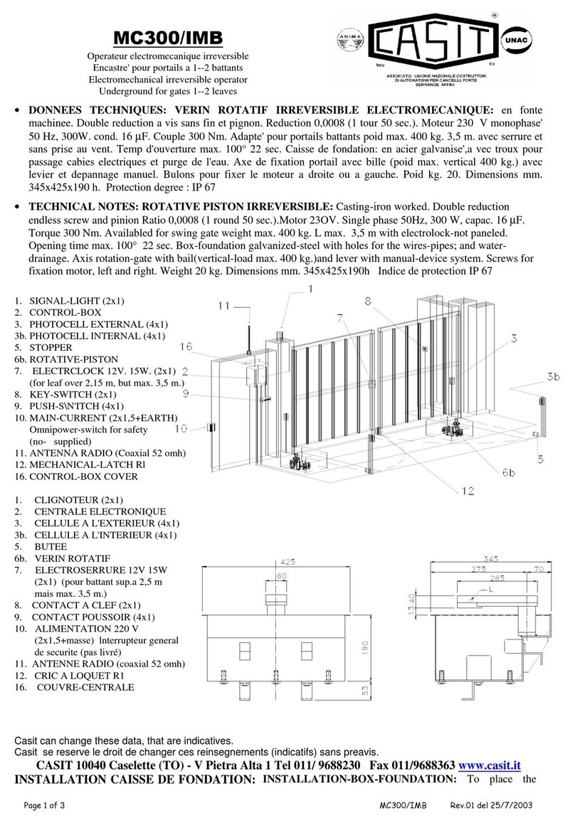
Other Casit Gate Opener manuals

Casit
Casit AF0051/ML Instruction Manual

Casit
Casit SCORRY500J User manual

Casit
Casit MC300/IMB User manual

Casit
Casit MC300/IM WINCH User manual

Casit
Casit MC300/R Instruction Manual

Casit
Casit MLA 400 User manual

Casit
Casit TORINO 06 Manual

Casit
Casit EQ2006 User manual

Casit
Casit EQ212 User manual

Casit
Casit SLIDY/S User manual
Popular Gate Opener manuals by other brands

GFA
GFA RP09/32RD installation instructions

cedamatic
cedamatic CE.ATM Operating instructions and spare parts catalogue

DoorHan
DoorHan SWING-3000 Installation and operating manual

Nice
Nice SLH400 Instructions and warnings for installation and use

CAME
CAME F500 quick start guide

Motorline professional
Motorline professional LINCE Series User's and installer's manual