Castel SAT802S User manual

China Aerospace Telecommunications Ltd
1
SAT802S
User Manual
V1.3
2014-11-24
China Aerospace Telecommunications Limited

China Aerospace Telecommunications Ltd
2
Content
1 Definition............................................................................................................................ 4
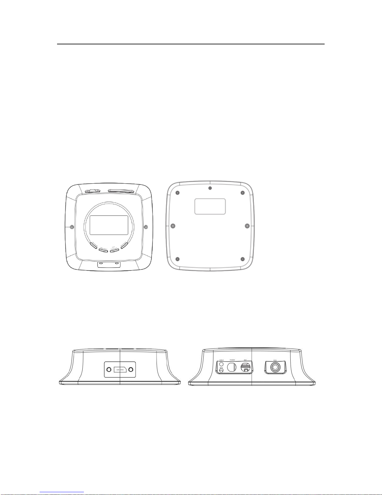
1.1 Hardware interface..................................................................................................................... 4
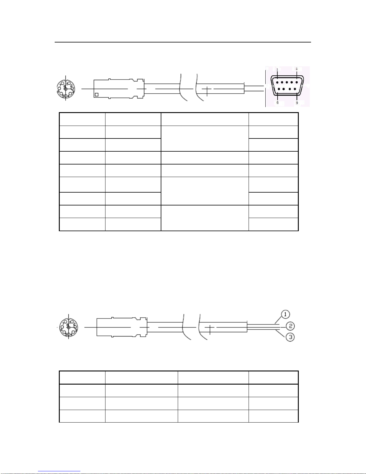
1.2 Handset port definition(Local setting and upgrading)............................................................ 5
1.3 Power and data transmission cable........................................................................................... 5
2 Functions ............................................................................................................................ 7
2.1 Device initialization..................................................................................................................... 7
2.2 Parameter settings ...................................................................................................................... 7
2.3 Working mechanism of data transparent transmission .......................................................... 8
2.4 LED indicator for working status.............................................................................................. 8
2.4.1 GSM status........................................................................................................................... 8
2.4.2 GPS status............................................................................................................................ 8
2.4.3 Iridium network .................................................................................................................. 8
2.4.4 Iridium sending status ........................................................................................................ 8
3 Setting Guide ...................................................................................................................... 9
3.1 CASTELECOM PC Tool Setting ......................................................................................... 9
3.2 Platform Parameter Setting .................................................................................................. 9
3.3 SMS Setting............................................................................................................................. 9
4 Installation Guide...............................................................................................................10
4.1 Installation of SIM card........................................................................................................... 10
4.2 Placement of SAT802S main unit.............................................................................................11
4.3 Installation of GPS antenna......................................................................................................11
4.4 Installation of Iridium antenna ................................................................................................11
4.5 Installation of power & data transmission cable.................................................................... 12
4.5.1 Link external power.......................................................................................................... 12
4.5.2 Link ACC cable ................................................................................................................. 13
5 Specific characters of SAT-802S..........................................................................................14
5.1 Electrical specification.............................................................................................................. 14
5.1.1 Electric parameters of main unit..................................................................................... 14
5.1.2 Iridium parameters........................................................................................................... 14
5.1.3 GSM parameters............................................................................................................... 14
5.1.4 GPS parameters................................................................................................................. 15
5.2 Mechanical specification .......................................................................................................... 15
6 FAQ...................................................................................................................................16

China Aerospace Telecommunications Ltd
3

China Aerospace Telecommunications Ltd
4
1 Definition
SAT-802S is dual mode Iridium&GSM tracker that combines with Iridium SBD and
GPRS to send gps data globally.
It is suitable for global vessel tracking solutions at lower cost by its intelligent
working mode.
Best choice for Air,Sea,Mountain,Desert,etc,anwhere on earth.Full coverage in
Globa,,No
Blind Area.
This device is using dual mode iridium &GSM communication to offer GPS tracking
which is consist of main box ,power supply, GPS antenna, iridium antenna and other
specific accessories. Following is main box external view:
1.1 Hardware interface
SAT802S host provides five external interfaces, that's Power supply & Data transmission
interface, Handset port interface, Iridium antenna interface, GSM antenna interface and GPS
antenna interface as shown below.

China Aerospace Telecommunications Ltd
5
1.2 Handset port definition(Local setting and upgrading)
Used for parameters setting and firmware upgrading.
1.3 Power and data transmission cable.
Pin number
Indication
Function
Color
1
RXD
Used for communicate
between device and port tool.
2
TXD
3
5V DC
4
Ground
5
SPK
Speeking
interface
6
SPK
7
MIC+
microphone
interface
8
MIC-
Pin number
Indication
Function
Color
1
Power DC9-36V
power input
Red(thick)
5
GND
Ground
Black(thick)
9
ACC
ACC input(+)
White

China Aerospace Telecommunications Ltd
6
2
Power out put DC 5V
5V DC
2*2 232
Interface
3
RXD
RXD 232
2*2 232
Interface
4
TXD
232 TXD
2*2 232
Interface
5
GND
Ground
2*2 232
Interface
6
VIN
VIN
Dark green
7
GND1
Ground
Blue
8
GND2
GND SOS
SOS
interface
10
SOS
I/O SOS
SOS
interface
11
Beep
I/O Beeper
Pink
12
OU1
I/O power control
Purple

China Aerospace Telecommunications Ltd
7
2 Functions
SAT-802S is dual mode Iridium&GSM tracker that combines with Iridium SBD and GPRS to
send gps data globally.
It is suitable for global vessel tracking solutions at lower cost by its intelligent working mode.
Best choice for Air,Sea,Mountain,Desert,etc,anywhere on earth.Full coverage in Globa,,No
Blind Area.
Features
Dual mode communication: Iridium SBDand GPRS.
Auto choose communication channel,GPRS is top priority.
Global GPS location tracking
Global text message transmission
Relative lower monthly cost
SOS
Geo-fence
Dual RS232 extend: temperature sensor,3 channel camera,LCD screen
5 I/O
OTA wireless upgrading
Air,Sea,Mountain,Desert,etc,anwhere on earth.Full coverage in Globa,,No Blind
Area.
Leverage on GSM and Iridium satellite networks,able to switch
automatically,depending on GSM
2.1 Device initialization
After host powers up, four indicators will fully light for 1 second, then fully turn off. Later,
terminal starts to initialization process.
If GPS module works well, after GPS has valid positioning, "GPS indicator" will start
blinking.
Meanwhile, GSM initialization begins. If initialization is successful, "GSM indicator" lights,
then dial to centre server. After a successful connection, "GSM indicator" starts blinking.
When GSM initialization finished, system will run Iridium module's initialization. If
successful, "Iridium network" indicator starts blinking.
2.2 Parameter settings
Device should set parameters before use. There is two ways for parameters setting. You can
set parameters through setting tool via device's Handset port, or set by monitoring center after
intergrading the protocol to your server.

China Aerospace Telecommunications Ltd
8
2.3 Working mechanism of data transparent transmission
Any data not being above-mentioned parameter format that terminal serial port received will
be considered as "user transparent transmission data", and according to channel status, data
will be sent to its destination by GPRS data link or Iridium SBD.
Bytes interval in the data packet of "user transparent transmission data" should not be larger
than 0.5 second and the length of each data packet should not be larger than 336 bytes. When
large amounts of data need to be transmitted, data will be divided into packets.
Data transmission between terminals has a data length limit with a maximum of 266 bytes.
As a response, after sending "user transparent transmission data", device then sends a "SEND
OK" message to external data device via serial port. After external data device receives this
response, it prepares to send next data packet.
In dual-mode communication, GPRS channel has priority. If condition meets < login failed or
heartbeat confirmation failed, reboot GPRS link connection, if failed, wait 30 seconds, then
again, if still failed after three times>, it will automatically switch to Iridium SBD
communication channel. In Iridium SBD communication channel mode, system still keep
booting GPRS link connection until connecting successfully, if connected, communication
mode turns to GPRS communication channel.
2.4 LED indicator for working status
2.4.1 GSM status
Blinking: GPRS network login success.
Always light: Do not login to GPRS network yet.
Turn off: sleep status, GSM does not work or GSM fault.
2.4.2 GPS status
Blinking: GPS positioned successfully.
Always light: searching signal.
Turn off: sleep status, GPS does not work or GPS fault.
2.4.3 Iridium network
Blinking: Iridium is in network service status.
Always light: Iridium is not in network service status.
Turn off: sleep status, Iridium does not work or Iridium fault.
2.4.4 Iridium sending status
Blinking: Iridium is receiving or sending data.

China Aerospace Telecommunications Ltd
9
3 Setting Guide
Terminal parameters can be set through CASTELECOM PC Tool, platform and SMS.
3.1 CASTELECOM PC Tool Setting
Professional setting tool “CASTELECOM PC Tool”can be installed in your computer.
For detailed using method, please refer to user manual.
CASTELECOM PC
Tool User Manual EN V0.2.pdf
For detailed description of PC Tool and PC Tool software, please download from
http://www.castelecom.com .
3.2 Platform Parameter Setting
After Terminal insert SIM card and power on, it will login into platform, then can set almost all
parameters remotely through platform. Such as the upload time interval, Area alarm, Temperature
alarm area, Preset Number etc.
3.3 SMS Setting
The first any phone number that be used to set or read parameters through SMS will
become the super authorized phone number. The other two authorized phone numbers can
be set by the super authorized phone number. For detailed using method, please refer to
user manual.
Remotely SMS
maintain guide.doc

China Aerospace Telecommunications Ltd
10
4 Installation Guide
The terminal integrate the GSM antenna in it .We need put in the SIM cart ,put on the
GPS antenna ,IRIDIUM antenna, and the power cable.
Specific as follows :
4.1 Installation of SIM card
Insert the SIM card before installation of the main unit. Operation steps of which are as
follows:
1) Open the side plate of the main unit with screw driver.
2) Insert the SIM cards by directing it at the card seat.

China Aerospace Telecommunications Ltd
11
3) Fix the side plate to the main unit, fasten the screw and secure it.
4.2 Placement of SAT802S main unit
The location for placement of the SAT802S main unit should be determined in advance. The
location should allow anti-humidity, avoidance of high-temperature area, and be far away
from magnetic field and other sensitive electronic equipment.
4.3 Installation of GPS antenna
GPS antenna must not be installed under metal baffle plate because it can hinder receipt of
GPS signals, thus affecting the normal monitoring and positioning of the SAT802S main unit.
Try to install GPS antenna as horizontally as possible. Place the convex upward, and its
included angle with the ground must not exceed 15 degrees. Besides, it must be fixed
securely.
4.4 Installation of Iridium antenna
Iridium antenna must not be installed under metal baffle plate because it can hinder
transmission and receipt of satellite signals. Try to install Iridium antenna as horizontally as
possible. Place the antenna upward without high buildings nearby and its included angle with
Face to sky

China Aerospace Telecommunications Ltd
12
the ground must not exceed 15 degrees. Besides, it must be fixed securely and far from GSM
antenna. It is recommended that the distance between Iridium antenna and GSM antenna
should be no less than 1.5m.
Warning!: Any change of the GPS, GSM and Iridium antennas’ feedback cable may affect
the normal working of the SAT802S.
4.5 Installation of power & data transmission cable
Power cable is consist of 3 core wire, including power input, ACC input, Ground.
The power input :DC 9-36V
REMARKS: link the cables correctly with the vehicle and then link to the device, fix firmly
to avoid any damage in shock.
4.5.1 Link external power
Main power input cable(red) is linked to positive pole of main power of automotive wiring,
and make sure it is permanently supply power(when main power of vehicle is off, the port is
still supplying power); GND(black(thick)) link to negative pole of main power or rely on
bonding.
Please make sure whether the vehicle power voltage is suitable for the device power voltage
range.
Please make sure positive pole of your power connected with the red wire;
otherwise the device will be damaged!
Pin number
Indication
Function
Color
1
Main power input
power input
Red
2
Ground
Ground
Black(thick)
3
ACC input
ACC input(+)
White

China Aerospace Telecommunications Ltd
13
4.5.2 Link ACC cable
Link ACC cable (Orange) to ON of vessel key. Link I/O power input (pink) to the positive
pole of main power of automotive wiring, I/O Ground is linked to negative pole of main
power of automotive wiring or rely on bonding.

China Aerospace Telecommunications Ltd
14
5 Specific characters of SAT-802S
5.1 Electrical specification
5.1.1 Electric parameters of main unit
Working voltage: 9V –36V DC
Data transmission: Iridium SBD and GPRS dual-mode communication
Positioning: GPS
Working current in data transceiving: <350 mA@13.8V
Working temperature: -30℃~ +70℃
Storage temperature: -40℃~ +85℃
RH(relative humility): 5%~95% (no frosting)
Protection degree: IP66
5.1.2 Iridium parameters
Iridium module: Iridium 9602
Frequency: 1616 ~1626.5 MHz
Output power: 1.36W
Receiving sensitivity: -118.5dBm at 50W (typically)
Global coverage, no blind areas.
Duplex mode: TDD (Time Division Duplex)
Upstream data: maximum length is 340 bytes
Downstream: maximum length is 270 bytes
Transmission delay: 10 –60 seconds (because of galaxy switch)
Input/Output impedance: 50Ω
Multiplex mode: TDMA/FDMA
Iridium antenna and interface: external antenna, SMA interface
Antenna gain: 2dBi
5.1.3 GSM parameters
GSM modules: SIMCOM SIM900
GSM/GPRS receiving frequency: 850/900/1800/1900MHZ quad-band

China Aerospace Telecommunications Ltd
15
Network communication protocol: embedded TCP/IP protocol stack, support TCP/IP
Receiving sensitivity: <-106dBm
Max sending power: GT850MHz Class4(2W),GSM1900MHz Class1(1W)
GPRS multi-channel level: GPRS CLASS 10
Compatible communication protocol: GSM/GPRS Phase2/2+
GPRS mobile location level: Class B
GSM antenna and interface: external antenna, SMA interface
Antenna gain: 2dBi
5.1.4 GPS parameters
Receiver: 50 channel u-blox 5 engine GPS L1 C/A code
Support: WAAS, EGNOS, MSAS, GAGAN
Max update rate: 4 Hz
Accuracy:
Positioning: 2.5 m CEP
SBAS: 2.0 m CEP
Capture:
Cold start: 32 s
Hot start: 32 s
Auxiliary start: < 1 s
Sensitivity:
Tracking: -160 dBm
Re-capture: -160 dBm
Cold start: -143 dBm
A-GPS: support AssistNow Online and AssistNow Offline, under OMA SUPL specification
Operating restrictions:
Speed: 500 m/s (972 knots)
Height: 50,000 m
Antenna: external active antenna, SMA interface
Antenna gain: 28dBi
5.2 Mechanical specification
Sheathing material: Aluminum alloy
Main unit size: 230mm (W)*68mm (H)*230mm (L)
Main unit weight: Approx. 400g

China Aerospace Telecommunications Ltd
16
6 FAQ
Fault indicator
possible reason
ways
Four lights off
No power input
Check whether the external
power is linked correctly.
device problem
Contact supplier
GPS indicator
permanently off
GPS antenna placed in unsuited place
Check whether the antenna is
faced to sky
GPS antenna damage
Change GPS antenna
Connect problem with GPS antenna
Check GPS antenna port and
fix firmly
device problem
Contact supplier
GSM indicator
permanently off
uninstall the SIM
Install the SIM
no charge
Charge the SIM
device problem
Contact supplier
Iridium indicator
permanently off
Problem in link between Iridium and
main board
Contact supplier.
Iridium indicator
permanently on
Iridium antenna placed in unsuited
place
Check whether the antenna is
faced to sky
Iridium module service stop
contact with Iridium service
operator
Iridium transmission
indicator permanently
on
Iridium antenna placed in unsuited
place
Check whether the antenna is
faced to sky
Receive frequent
alarms
SOS button did not reset
Error in button, change
button
Monitor center did
not get data from
device
Long time interval of GPS sending
Set appropriate time interval
Set commands to stop sending data
Reset and allow gps data
sending
SIM installation wrong
Re-install SIM
SIM card problem
Check whether SIM can
support GPRS.
APN setting wrong
Consult local cellular service
provider
IP address setting wrong
Reset parameters: IP, Port.
Table of contents
Other Castel GPS manuals