manuals.online logo
Brands
  1. Home
  2. •
  3. Brands
  4. •
  5. Cavius
  6. •
  7. Smoke Alarm
  8. •
  9. Cavius LUMI-PLUGIN LP120 User manual

Cavius LUMI-PLUGIN LP120 User manual

Importantinformation
• The luminaire and heat alarm must be installed in accordance
with local wiring regulations if in doubt seek advice from a
qualied electrician.
• Before installing or completing maintenance work on the
luminaire and heat alarm make sure the mains power
is switched off.
• The luminaire and heat alarm is designed for indoor use only.
• The luminaire is dimmable, a trailing-edge dimmer must be
used.
• The light source of this luminaire is not replaceable; when the
light source reaches its end of life the whole luminaire must
be replaced.
• The luminaire is re rated 30/60/90 minutes under
EN1365- 2014 re test.
• The driver provided is the only driver that can be used with
this luminaire.
• The heat alarm can only be installed within the Lumi-Plugin
luminaire and not as a single unit.
• The heat alarm is powered by mains power (110-230V AC),
with a CR2 lithium back-up battery.
• The heat alarm can be RF interlinked with other alarms in the
CAVIUS Wireless Family.
• The Maximum number of alarms that can be interlinked within
a house group is 32.
• The distance between interlinked alarms depends on the house
layout and should always be tested after installation. It is not
advised to install alarms with a separation of more than 10m.
• The best areas to install the heat alarms:
• Areas not suitable for smoke alarms due to high risk of
false alarms
• Kitchen area
• Bathroom
• Garage or workshop
• Do not install the heat alarms:
• In rooms where the temperature goes
outside -10oC to +50oC.
• Bedrooms
• Lounge
• Dining room
• Hallway
• Family room
Installation and Specication Sheet
LP120 Main Powered Heat Alarm Downlight
Downlight specication
Brand: Lumi-Plugin
Available Colours: White or Chrome
IP Rating: IP65
Material: Mixed (Metal and Plastic)
Input Voltage to luminaire 16V
Input Voltage to Driver 220V - 240V 50/60Hz
Power Output: 9.5W
Colour Temp: 4000K or 2700K
Light Colour: Cool White or Warm White
Dimmable: Yes
Fire Rating: 30/60/90
Luminaires per pack: 1
Product Diameter: 120mm
Product Depth: 70mm
Hours: 50,000
Lumens: 700L
Beam Angle: 60°
Heat alarm specication
Brand: Lumi-Plugin
Battery Type: Replaceable CR2
Operation AC/DC: 110V AC, 230V AC
Range: Minimum 100m in open eld
Power Consumption: 161mAh in non-alarm condition
Interlink Frequency: 868MHZ
Sound: Audible indicator min 85dB @ 3
meter in anechoic successive tones
5 Year
Warranty
5
50,000
Hours
16V CE MarkBeam Angle
is 60°
Fire Rated
30/60/90
Dimmable 700
Lumens
Driver
Included
LP120WH/WARM/MBR/HA - LP120WH/COOL/MBR/HA
Installation instructions
1) Cut a circular hole in the ceiling (A) 92mm in diameter where
the luminaire is going to be installed. Do not exceed the
cutting diameter. (Diagram 1)
2) Remove the screws on the LED driver(D) and remove end cap.
Take a supply feed from the lighting radial circuit (B). Strip off
the end of the cable (C) and connect to the LED driver (D). Put
the end cap back onto the LED driver (D) and insert screws.
(Diagram 2)
3) Connect the LED Driver output cable to the luminaire. Feed the
mains supply cable (B) and LED driver (D) back through the
92mm cut out hole. (Diagram 3)
4) The heat alarm is held within the luminaire using magnets.
The alarm comes with a cable tted. Ensure the cable is
coming out of the back of the luminaire and connect to the
mains power.
5) Lift both springs so they are in the upwards position then
insert the luminaire into the 92mm cut out hole in the ceiling.
Make sure no cables are trapped under the springs and that
the luminaire is centred in the hole.
Please note: The alarm is delivered in the packaging with a dust
cover, installed to protect the alarm for exposure to excessive
dust which could potentially damage or reduce the function
of the alarm while the building is under construction. The dust
cover must be removed after the building is fully cleaned.
4
4
6 x Screws
2 x Cable Retainer
Mains Powered Heat Alarm.
LED Driver, complete with mini connector.
Lumi-Plugin LED Downlight including
spring clips.
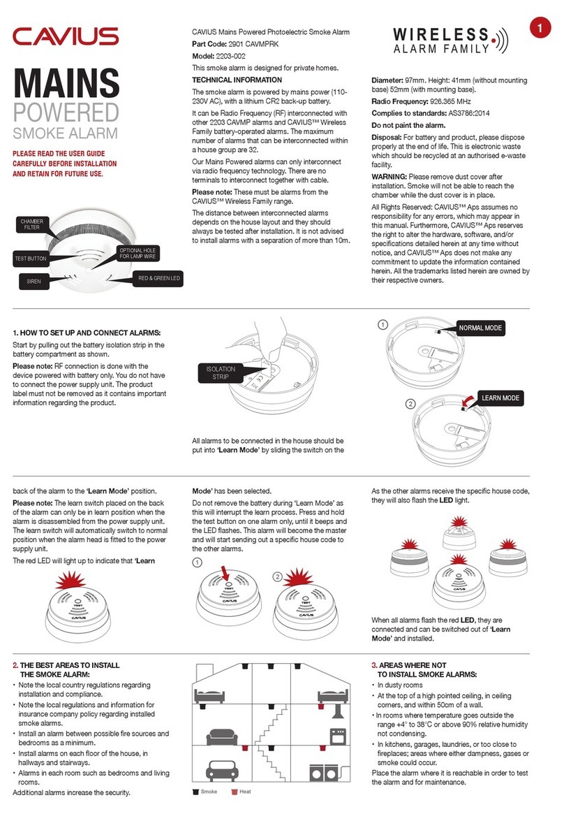
How to set up and connect alarms
1) Pull down the heat alarm away from the luminaire so the
magnets are not connected anymore. (Diagram 5)
2) Twist the heat alarm anti clockwise to release the alarm
from the mains power.
3) Pull out the battery isolation strip in the battery
compartment as shown (Diagram 6)
Please note: RF connection is done with the device
powered with the battery only. You do not have to
connect the power supply. The product label must not be
removed as it contains important information regarding
the product.
4) All alarms to be connected in the house should be put
into ‘Learn Mode’ by sliding the switch on the back of the
alarm to the ‘Learn Mode’ position. (Diagram 7)
Please note: The learn switch placed on the back of
the alarm can only be in learn position when the alarm
is disassembled from the power supply unit. The learn
switch will automatically switch to normal position when
the alarm head is tted to the power supply.
5) The red LED will light up to indicate that ‘Learn Mode’ has
been selected. Do not remove the battery during ‘Learn
Mode’ as this will interrupt the learn process.
6) Press and hold the test button on one alarm only, until
It beeps and the red LED ashes. This alarm will then
become the master and will start sending out a specic
house code to the other alarms. As the other alarms
receive the specic house code, their red LED will also
ash. When all alarms are ashing, they are connected
and can be switched out of ‘Learn Mode’ and installed
back within the luminaires.
Changing the heat alarm battery
1) Pull down the heat alarm so the magnets are not
connected to the luminaire. (Diagram 5)
2) Twist the heat alarm anti clockwise to release the alarm
from the mains power.
3) On the back of the alarm remove the cap over the battery
(Diagram 8)
4) Remove the battery and replace with a new battery
(Diagram 9)
Please note: You will not be able to install the heat alarm
without a battery being in the alarm and a CR2 battery is the only battery that can be used.
Testing the heat alarm
After installation, and at least once a month, test all of your alarms to ensure they are operating correctly and are within range of each
other (Diagram 10).
It is recommended to check visually every week if the LED ashes correctly (Every 48 seconds).
Press the test button on any alarm (This is on the front plate of the alarm) for at least 10 seconds. This will send out a test signal from
the alarm; all other connected alarms will receive the signal within a short time and the LED will ash every 8 seconds for two minutes.
Please note: Test function also transmits a weaker RF signal to ensure an optimal operation in normal conditions.
When the test signal is sent out, the alarms will respond in two ways:
1. A single beep every 8 seconds indicates that the alarms are connected and functioning.
2. Three short beeps every 8 seconds indicates a heat sensor fault. The alarm should be cleaned by running the vacuum (on a low
setting) around the heat alarm chamber and tested again.
If required this indication can be stopped early on each alarm by a short press of the test button.
If the problem continues please contact Lumi-Plugin.
5 6
Click!
Learn
Mode
Set / Test
10
7
Heat Alarm Power Supply
8
9
Call +44 (0)33 0380 1329 or visit
lumi-plugin.com for more information
5 Year
Warranty
5
50,000
Hours
16V CE MarkBeam Angle
is 60°
Fire Rated
30/60/90
Dimmable 700
Lumens
Driver
Included
Developed by CAVIUS Aps for Sleep Safe Systems Limited
T/A Lumi-Plugin - Lindenmuth House, 37 Lindenmuth Way, Greenham Business Park, Newbury, Berkshire, RG19 6HW
Manufactured in P.R.C.
Normal mode
In normal mode the LED will ash every 48 seconds to show
correct operation.
The green LED is on when the alarm is connected to mains power.
It may take up to 1 minute to indicate that mains power has been
connected.
Alarm mode
When the heat is detected, the heat alarm will go into ‘Alarm
Mode’. It will sound the alarm signal and the red LED will ash.
The heat alarm will also transmit the alarm signal to the other
connected alarms, which will also sound the alarm signal after
a short delay.
The CAVIUS Wireless Family have two different alarm signals:
Alarm Signal 1 --- --- --- is a life threatening alarm, like a smoke
alarm.
Alarm Signal 2 - - - is a non-life-threatening alarm, like
a ooding alarm:
Smoke alarm signal: --- --- ---
Heat alarm signal: --- --- ---
Flood alarm signal: - - -
CO alarm low level signal: - - -
CO alarm high level signal: --- --- ---
Please note: Only the originating alarm’s red LED will ash,
so it can be identied.
Pause/hushfunction
If the heat alarms are to set into a false alarm by cooking,
replace, etc. they can be paused for 10 minutes by pressing the
test button on the originating heat alarm only (indicated by the
ashing LED).
The reason for this is that it is necessary to locate the source of
the alarm before using the hush function. This is to make sure
that it is not a life threatening situation.
Low batterysignal
Your product has a battery back-up with a 1 year life in battery
mode without mains power, and up to 10 years normal life with
mains. However, we recommend to replace the battery every 5
years.
When the battery is starting its end of life, a short beep will
sound out every 48 seconds for 30 days.
Maintenance &troubleshooting
The heat alarm should be vacuum cleaned once per quarter, to
remove dust particles, and it can be wiped with a damp cloth.
(Do not open the alarm).
Please note: You can easily vacuum clean the heat chamber
through the dedicated openings in the top cover, and it’s possible
to test the alarms by pressing the cover at the same time.
High humidity condensing which can be resolved by drying the
heat alarm.
If the heat alarm does not work when the test button is pushed,
the probable cause is a power failure. Always test the alarm after
replacement of battery.
Guarantee
• This luminaire is guaranteed for a period of 5 years
or 50,000 hours - depending which comes rst.
• The heat alarm is guaranteed for a period of 2 years.
• The guarantee period is invalid if the product has been
tampered with; if any of the product labels, manufacturing
labels, rating labels or serial labels have been removed; or
the product has not been installed in accordance with
local wiring regulations.
• If the product fails within the guaranteed period, Sleep Safe
Systems Limited T/A Lumi-Plugin will replace the product free
of charge but take no responsibility for installation, operation
or maintenance costs.
• Lumi-Plugin reserves the right to change the product
specication without notice.
Other Cavius Smoke Alarm manuals

Cavius 2103 User manual

Cavius

Cavius 2103 User manual

Cavius 2104-001 User manual

Cavius

Cavius 2104-001 User manual

Cavius 2103-002 User manual

Cavius

Cavius 2103-002 User manual

Cavius 3002-TK001 User manual

Cavius

Cavius 3002-TK001 User manual

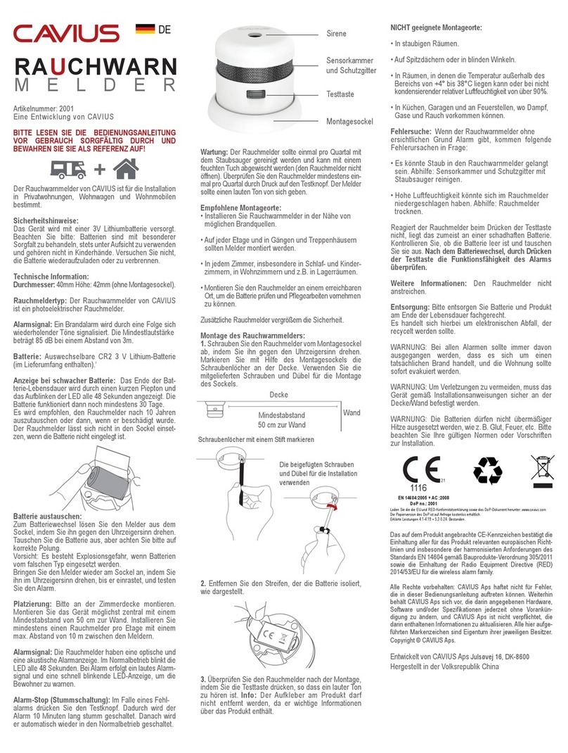
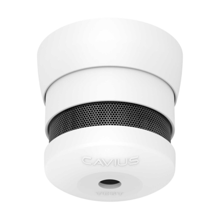
Cavius RAUCHWARN MELDER User manual

Cavius

Cavius RAUCHWARN MELDER User manual

Cavius 2208 User manual

Cavius

Cavius 2208 User manual

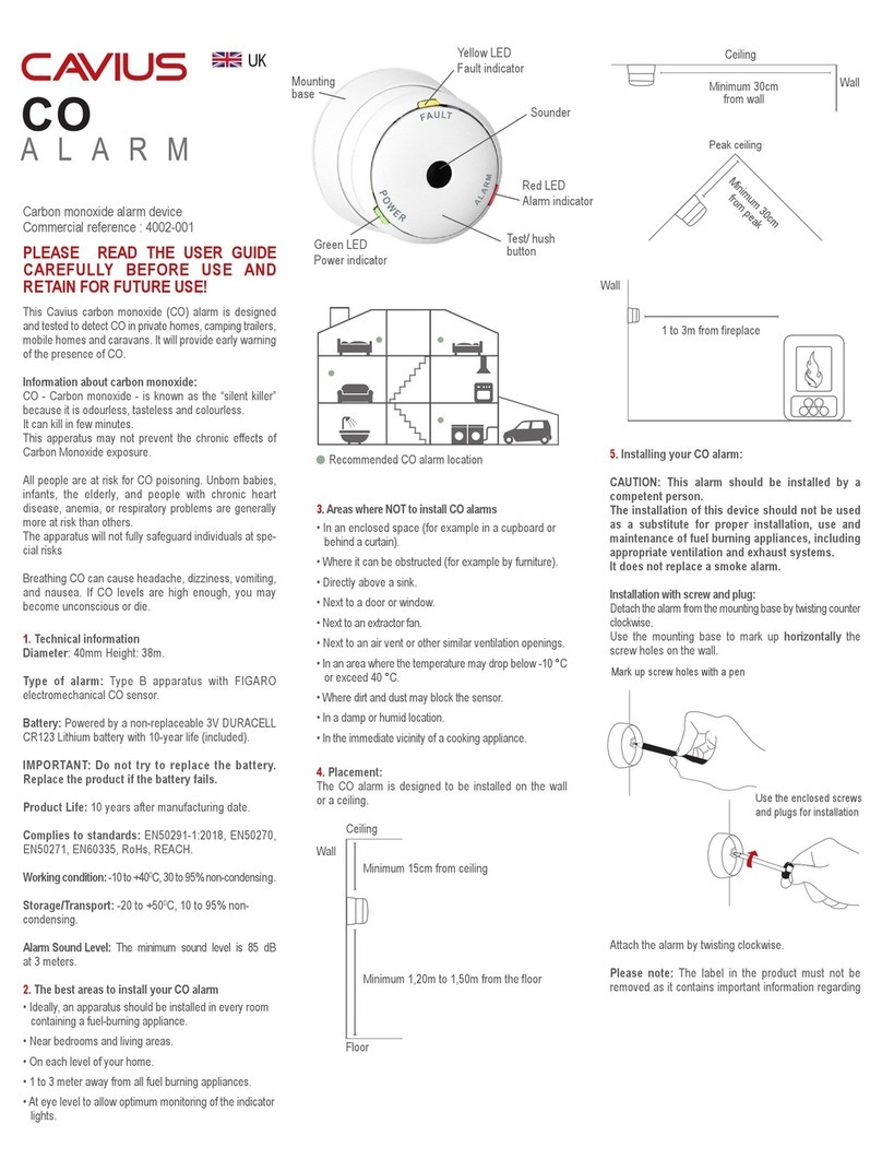
Cavius 4002-001 User manual

Cavius

Cavius 4002-001 User manual

Cavius 2201-003 User manual

Cavius

Cavius 2201-003 User manual

Cavius 2107-001 User manual

Cavius

Cavius 2107-001 User manual

Cavius 2106-003 User manual

Cavius

Cavius 2106-003 User manual

Cavius 2008-002 User manual

Cavius

Cavius 2008-002 User manual

Cavius 2203-002 User manual

Cavius

Cavius 2203-002 User manual

Cavius 2107-001 User manual

Cavius

Cavius 2107-001 User manual

Cavius 2008-001 User manual

Cavius

Cavius 2008-001 User manual

Cavius 4002-001 User manual

Cavius

Cavius 4002-001 User manual

Cavius 2007-003 User manual

Cavius

Cavius 2007-003 User manual

Cavius 3103-002 User manual

Cavius

Cavius 3103-002 User manual

Cavius 2203-002 User manual

Cavius

Cavius 2203-002 User manual

Cavius 3104-001 User manual

Cavius

Cavius 3104-001 User manual

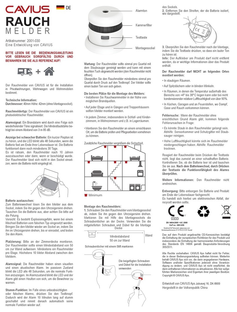
Cavius 2001-030 User manual

Cavius

Cavius 2001-030 User manual

Popular Smoke Alarm manuals by other brands

Eminent EM6590 E-Domotica user manual

Eminent

Eminent EM6590 E-Domotica user manual

x-sense SD19-W user manual

x-sense

x-sense SD19-W user manual

Vision ZS6301N Installation & operation manual

Vision

Vision ZS6301N Installation & operation manual

Kidde i9010 user guide

Kidde

Kidde i9010 user guide

GE TX-6010-01-1 manual

GE

GE TX-6010-01-1 manual

FireAngel Thermoptek WST-630 user manual

FireAngel

FireAngel Thermoptek WST-630 user manual

System Sensor FAAST 7100X Installation and maintenance manual

System Sensor

System Sensor FAAST 7100X Installation and maintenance manual

Kidde 3050-VDSC10 user guide

Kidde

Kidde 3050-VDSC10 user guide

Doepke Dupline DRD 2 operating instructions

Doepke

Doepke Dupline DRD 2 operating instructions

AJAX FireProtect 2 Jeweller manual

AJAX

AJAX FireProtect 2 Jeweller manual

DSC FSA-410A Installation and operating instructions

DSC

DSC FSA-410A Installation and operating instructions

HST HP101U Installation and operation manual

HST

HST HP101U Installation and operation manual

Siterwell GS517 user manual

Siterwell

Siterwell GS517 user manual

Kidde P12040 user guide

Kidde

Kidde P12040 user guide

WAGNER Titanus Micro-Sens Technical manual

WAGNER

WAGNER Titanus Micro-Sens Technical manual

Siterwell GS522C user manual

Siterwell

Siterwell GS522C user manual

Vitek VT-SMKC1 manual

Vitek

Vitek VT-SMKC1 manual

GST C-9403 Quick start quide

GST

GST C-9403 Quick start quide

manuals.online logo
manuals.online logoBrands
  • About & Mission
  • Contact us
  • Privacy Policy
  • Terms and Conditions

Copyright 2025 Manuals.Online. All Rights Reserved.