CBC PT110N User manual

P
PT
T1
11
10
0N
N/
/P
PT
T1
11
10
0N
N-
-X
XT
T
Vandal Resistant 10x PTZ Dome
User Manual
NY: 55 Mall Drive • Commack, NY 11725 (800) 422-6707
CA
: 20521 Earl Street • Torrance, CA 90503 (800) 888-0131
www.computarganz.com

CONTENTS
○
1Introduction
Features
3
Product & Accessories
5
Parts Name & Functions
7
○
2Installation
DIP Switch Setup
8
Installation using Ceiling Mount Bracket
11
Installation using Wall Mount Bracket
12
Installation using Flush Mount Bracket
13
Cabling
14
○
3Operation
Check Points before Operation
17
Preset and Pattern Function Pre-Check
17
Starting OSD Menu
18
Reserved Preset
18
Preset
19
Swing
19
Pattern
20
Group
21
Other Functions
22
OSD Display of Main Screen
23
○
4How to use OSD Menu
General Rules of Key Operation for Menu
24
Main Menu
24
Display Setup
25
Privacy Zone Mask Setup
26
Camera Setup
27
Motion Setup
30
Preset Setup
32
Swing Setup
33
Pattern Setup
34
Group Setup
35
System Initialize
37
○
5Specifications
38
39
Dimensions

Speed Dome Camera Instruction Manual 3
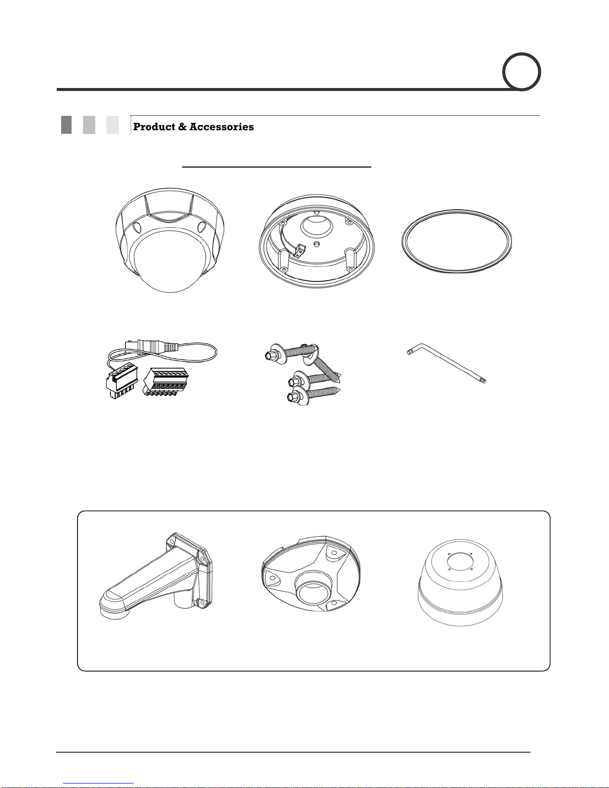
Features
Camera Specifications
zCCD Sensor : 1/4" Interline Transf
zZoom Magnification : ×10 Optical Zoom, ×10 Digital Zoom (Max 100 Zoom)
zDay & Night Function
zVariable Focus Mode: Auto-F
zIndependent & Simultaneo
Advanced Pan/Tilt Functions
zMax. 360°/sec high speed Pan/Ti
zUsing Vector Drive Technol esult,
time to target view is reduced dramatically and
zFor jog operation using a controller, an ultra slow speed very
easy to relocate camera to the desired target view. Add
desired position with zoom-proportional pan/tilt moveme
.
Preset, Pattern, Swing, Group, Privacy Mask and More…
zMax. 127 Presets are assignable an can be set up independently, such as
White Balance, Auto Ex
zMax. 8 set of Swing actions can be stored. This en two
preset positions at a designated speed.
zMax. 4 Patterns can be recorded and played ba any
trajectory preset by joystick as closely as possible.
zMax. 8 set of Group action can be stored. Thi
combination of Preset or Pattern or Swing. A G
Pattern/Swings.
zPrivacy Masks are assignable, so as not to intrude on other’
PTZ (Pan/Tilt/Zoom) Control
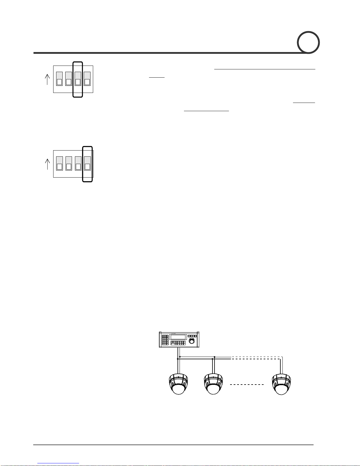
zWith RS-485 communication, max. of 255 cameras can be controlled at the same time.
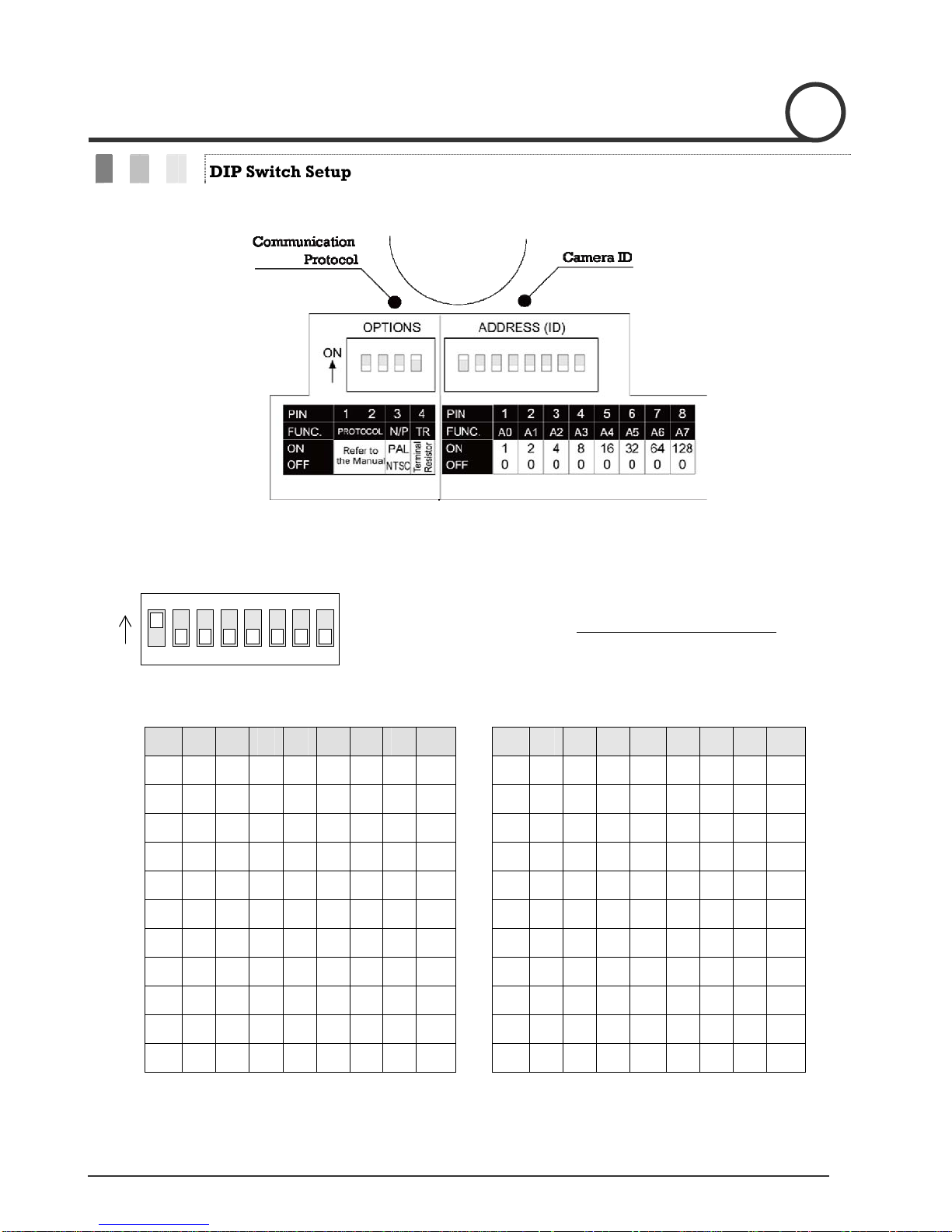
zPelco-D or Pelco-P protocol can be selected as a contr
INTROD 1
er CCD
×
ocus / Manual Focus / Semi-Auto Focus.
us Camera Characteristic Setup in Preset operation
lt Motion
ogy, Pan/Tilt motions are accomplished with the shortest path. As a r
the video stream transfers are natural to watch.
of 0.05°/sec can be reached, making it
itionally, it is easy to move the camera to a
nt.
d characteristics of each preset
posure, Label and so on.
ables camera to move automatically between
ck. This enables camera to automatically follow
senables camera to move automatically with a
roup is composed of max. 20 entities of Preset/
s privacy. (4 Privacy Zones)
ol protocol in the current firmware version.
UCTION

Speed Dome Camera Instruction Manual 4
OSD (On Screen Display) Menu
rovided to display the status of camera and to configure the functions interactively.
zThe information such as Camera ID, Pan/Tilt Angle, Alarm Input and Preset can be displayed on screen.
te external electric noise and shock, alarm sensor Input is decoupled from photo
ng Preset position.
urpose
easily and directly with reserved preset, without entering the
ms.
zOSD menu is p
Alarm I/O Functions
z4 alarm sensor Inputs are available.
zTo completely elimina
coupler.
zIf an external sensor is activated, camera can be set to move to the correspondi
Reserved Presets for Special P
zMost camera characteristics can be set up
OSD menu. For more information, refer to “Reserved Preset” in this manual.
IP66 (weather resistant) *(PT110N-XT model only).
zThis product has been certified to the IP66 standard for waterproof and spray proof environments. Also
for the same reason it can be protected from dust and rainstor
INTRODUCTION 1

Speed Dome Camera Instruction Manual 5
Product & Accessories
Product & Accessories- PT110N-XT model (outdoor).
zMain Body zMount Adapter zGasket(Rubber)
zTerminalBlock z
Videocable
Options
zWallMountBracket zCeilingMountBracket zSun shield
INTRODUCTION 1
zScrews Six angles wrench

Speed Dome Camera Instruction Manual 6
model (indoor)Product & Accessories- PT110N .
zMain Body zSurface Mount Bracket zScrews & Terminal Block
Options
zIn-Ceiling Mount Bracket zCeilingMountBracket zWall Mount Bracket
INTRODUCTION 1

Speed Dome Camera Instruction Manual 7
Parts Name & Functions
Do not remove protecti l
ve vinyl from dome cover before finishing alzDome Cover
installation processes to protect dome cover from scratches or dust.
t is used for installing either a ceiling mount
or wall mount bracket. Separate the cover first and then attach it
directly to ceiling. Camera must be assembled at the last stage.
zGasket (PT110N-XT
model only)
zLockup Screw
Protect it from dust and rainstorm. Move projecting part of the gasket
which should be placed on the low to main body position
Fixes main unit to surface mount bracket.
zCabling Terminal Block
During installation, Power, Video, Communication, Alarm Input cables
are connected on to this cabling terminal block.
Pull out from Surface Mount Bracket and connect to Main Body hook.
zDIP Switch
zFall-proof spring
Adjusts camera ID and protocols.
After installing fall-proof spring on Bracket , hang on the safety ring to
protect the camera from falling
Main Unit / Surface Mount Bracket
zSurface Mount Bracket The surface mount bracke
INTRODUCTION 1
DIP Switch
Cabling Terminal Block
Back of Main Unit
MountAdapter
Lock-up Screw
Dome Cover
Safety Retention Spring
Main Body
Gasket (PT110N-
XT Model only)

Speed Dome Camera Instruction Manual 8
DIP Switch Setup
Before you install the camera, you should set the DIP switches to configure the camera ID and communication
protocol.
Camera ID Setup
123456
ON
ON
78
Pin 1 2 3 4 5 6 7 8 Pin
1 2 3 4 5 6 7 8
ID 1 2 4 8 16 32 64
128
ID 1 2 4 8 16 32 64 128
1 on off off off off off off
off 11 on
on
off
on off off off off
2 off on off off off off off
off 12 off
off
on
on off off off off
3 on on off off off off off
off 13 on
off
on
on off off off off
4 off off on off off off off
off 14 off
on
on
on off off off off
5 on off on off off off off
off 15 on
on
on
on off off off Off
6 off on on off off off off
off 16 off
off
off
off on off off off
7 on on on off off off off
off 17 on
off
off
off on off off off
8 off off off on off off off
off 18 off
on
off
off on off off off
9 on off off on off off off
off 19 on
on
off
Off
on off off off
10 off on off on off off off
off
20 off
off
on
off on off off off
zThe ID number of camera is set using a binary number. Examples
shown below.
zThe range of ID is 1~255. Do not use 0 as camera ID. Factor y
default of Camera ID is 1.
u want to control a c amera, you must match the camera
ID with Cam ID setting of DVR or Controller.
zIf yo ertain c
2
INSTALLATION

Speed Dome Camera Instruction Manual 9
Communication Protocol Setup
1234
ON
ON
Reserved for Supplier
zapprop col with DIP switch combination.Select the riate Proto
Switch St tea
P0
(Pin 1)
P1
(Pin 2)
Protocol
OFF OFF PELCO-D, 2400 bps
ON OFF PELCO-D, 9600 bps
OFF ON PELCO-P, 4800 bps
ON ON PELCO-P, 9600 bps
zIf you want to control using DVR or P/T controller, their protocol must
nnotbe identical to camera. Otherwise, you ca control the camera.
zIf you changed camera protocol by changing DIP S/W, the change
z”.
will be effective after you reboot the camera.
Factory default of protocol is “Pelco-D, 2400 bps
INSTALLATION 2
Pin 1 2 3 4 5 6 7 8 Pin
1 2 3 4 5 6 7 8
ID 1 2 4 8 16 32 64
128
ID 1 2 4 8 16 32 64 128
21 n off on off on off offo
off 31 on
on
on
on
on off off off
22 off on on off on off off
off 32 off
off
off
off
off on off off
23 off offon on on off on
off 33 on
off
off
off
off on off off
24 off off off on on off off
off 34 off
on
off
off
off on off off
25 on off off on on off off
off 35 on
on
off
off
off on off Off
26 off on off on on off off
of 36 offf
off
on
off
Off on off off
27 on on off on on off off
off 37 on
off
on
off
Off on off off
28 off off on on on off off
off 38 off
on
on
off
Off on off off
29 on off on on on off off
off 39 on
on
on
off
Off on off off
30 off on on on on off off
off
f40 of
off
off
on
Off on off off

Speed Dome Camera Instruction Manual 10
1234
ON
O
N
Terminal Resistor Setup
1234
ON
ON
zPin 3 is only for supplier, DO NOT CHANGE THESE ITS ORIGINAL
STATE.If you change one of these, proper operation can not be
achieved.
~Pin 3 PAL / NTSC system selection of Camera. DO NOT
CHANGE THIS PIN.
INSTALLATION
2
T
erminal resistor is used if your system meets one of following two
c
onditional cases.
zCase1: Control cable between camera and controller is
relatively long (1:1 connection)
If communication cable is very long, the electrical signal will bind in
the terminal point. This reflected signal causes signal distortion,
r
t r of both sides (i.e. camera and controller) must be
s
zC he same time
Due to similar reasons stated in case 1, the terminal resisters of the
controller and a must be set to ‘ON’ ate he
camer the longes l s to the
er Do not o re o
esulting in a degradation of camera function. In this case, the
erminal resisto
et to the ‘ON’ state.
ase2: Multiple cameras are controlled at t
the last camer st . T
a with t cab e length i determined be ‘last’
cam a. turn n the terminal sist r of all cameras.
Controller
#1 #2 #n
Terminal Resistor ON
RS-485
Termin l Resi
OFF
Te a s
OFF
T n si
ON
a stor rmin l Resi tor ermi al Re stor

Speed Dome Camera Instruction Manual 11
Installation using Ceiling Mount Brack t e
①After putting t et
Fa in k o li
screws.
he Gask on the ceiling
sten ceil g mount brac et t cei ng with 3
②Wire cables to als and
terminals to main unit. Do not use surface mount
r t
termin connect the
b acke !
① ng
② Rem
Hang the camera on the safety ri
assemble it using the fall-proof spring.
and o tective vin
ve pro yl from dome cover.
INSTALLATIONINSTALLATIONINSTALLATION 2

Speed Dome Camera Instruction Manual 12
Installation using W la l Mount Bracket
①After putting the Gasket on the wa
Fasten wall mount bracket to ceiling with 4
screws.
ll
②Wire cables to terminals and connect the
terminals to main unit. Do not use surface
mount bracket!
③ Fasten main unit to wall mount br
screws.
acket with 4
④ Remove protective vinyl from dome cover.
2

Speed Dome Camera Instruction Manual 13
Installation using Flush Mount Bracket
.
2
③ Connect fall-proof spring to main body
hook. Assemble and fasten with screws.
u 3 n main body bracket with flush mount
bracket. Fasten with screws.
④ Put main body and bracket assembly into
main hole.
the
①C t holes in ceiling ② Alig
⑥ Cover assembly with bracket
cover and turn it clockwise.
⑤ Secure flush mount bracket to the ceiling
with screws through the 3 holes on
bracket.
INSTALLATION

Speed Dome Camera Instruction Manual 14
Cabling
Power
IN COM+
IN1
IN2
IN3
IN4
PWR(+)
PWR(-)
F.G
RS-485(+)
RS-485(-)
Cabling Terminal Block
VIDEO(+)
VIDEO(-)
Controller/ DVR
Moinitor
BNC Sensor
IrDA
Sensor
Door
Switch
Power Connection
zPlease check the voltage and current capacity of rated power carefully. Rated power is indicated on the
back of main unit.
Rated Power Input Voltage Range Current Consumption
AC 24V (PT110N) AC 17V ~ 29V 0.4 A
AC 24V (PT110N-XT) AC 17V ~ 29V 1.5 A
zDC power loss increases over distance. DC to cameras sho short as possible.
RS-485 Communication
zFor PTZ control, connect the RS-485 line to keyboard and DVR. To control multiple cameras on the same line
with simultaneous operation (see page 13 for resistor settings): the RS-485 communication lines to cameras
are connected in parallel as shown below.
power wiring uld be kept as

Speed Dome Camera Instruction Manual 15
e C nVid o o nection
zBNC coaxial cConnect with able.
Alarm Input Connection
zSensor Input
Before connecting sensors, check the sensor driver voltage and output signal type. Since sensor output
signal types are divided into Open Collector and Voltage Output types in general, the cabling must be
stalled properly depending on the signal type.
in
Signal Description
IN COM+ Connect (+) cable of electric power source for Sensors to this port as
shown in the circuit above.
IN1−, IN2−, IN3−, IN4−Connect output of sensors for each port as shown in the circuit above.
INSTALLATION 2
Internal
SENSOR COM
(GND)
SENSOR IN1
SENSOR COM
(GND)
SENSOR IN2
SENSOR COM
(GND)
SENSOR IN3
SENSOR COM
(GND)
SENSOR IN4

Speed Dome Camera Instruction Manual 16
If you want to use Alarm Input, the type of sensor must be selected in OSD menu. The sensor types are
Normal Open and Normal Close. If the sensor type is not selected properly, alarm activation will occur
opposite of what is desired.
~Normal Open Output Voltage is high state when sensor is activated
~Normal Close Output Voltage is high state when sensor is not activated
INSTALLATION
2

Speed Dome Camera Instruction Manual 17
Check Points before Operation
zBefore power is applied, please check the cables carefully.
The camera ID of the controller must be identical to that of the target camera. The camera ID can be checked by
f the camera.
zIf yo r controller supports multi-protocols, the protocol must be changed to match to that of the camera.
zIf you changed camera protocol by changing DIP switch, the change will be effective after you reboot the
amera.
zSince the operation method can be different for each controller available, refer to the manual for your controller
if camera can not be controlled properly. The operation of this manual is based on the standard Pelco®
Controller.
z
reading DIP switch o
u
c
Preset and Pattern Function Pre-Check
zCheck controller or DVR preset and pattern functions in advance when using controller or DVR.
zRefe following table when using standard Pelco® protocol controller.r to the
< Go Preset > Input [Preset Number] and press [Preset] button.
< Set Preset > Input [Preset Number] and press [Preset] button for more than 2 seconds.
< Run Pattern > Input [Pattern Number] and press [Pattern] button.
< Set Pattern > Input [Pattern Number] and press [Pattern] button for more than 2 seconds.
zIf c
info
ontroller or DVR has no pattern button or function, use shortcut keys with preset numbers. For more
rmation, refer to “Reserved Preset” in this manual.
OPERATION 3

Speed Dome Camera Instruction Manual 18
Starting OSD Menu
zFunction
or each application
zEnter M o Prese
Using the OSD menu, Preset, Pattern, Swing, Group and Alarm Input function can be
configured f
enu <G t> [95]
Reserved Preset
zDescription Some Preset numbers are reserved to special functions.
zFunction Go Preset [95] : Enters into OSD menu
Go Preset [131~134] : Runs Pattern Function 1 ~ 4
Go Preset [141~148] : Runs Swing Function 1 ~ 8
Go Preset [151~158] : Runs Group Function 1 ~ 8
Go Preset [170] : Sets Camera BLC Mode to OFF
Go Preset [171] : Sets Camera BLC Mode to ON
Go Preset [174] : Sets Camera Focus Mode to AUTO
Go Preset [175] : Sets Camera Focus Mode to Manual
Go Preset [176] : Sets Camera Focus Mode to SEMI-AUTO
Go Preset [177] : Sets Day & Night Mode to AUTO
Go Preset [178] : Sets Day & Night Mode to NIGHT
Go Preset [179] : Sets Day & Night Mode to DAY
Go Preset [190] : Sets OSD Display Mode to AUTO (Except Privacy Mask)
Go Preset [191] : Sets OSD Display Mode to OFF (Except Privacy Mask)
Go Preset [192] : Setting OSD Display Mode to ON (Except Privacy Mask)
Go Preset [193] : Sets all Privacy Mask Display to OFF
Go Preset [194] : Sets all Privacy Mask Display to ON
OPERATION 3

Speed Dome Camera Instruction Manual 19
Preset
Preset position. The Preset number can be
acteristics (i.e. White Balance, Auto Exposure) can be set up
be
set to "GLOBAL" as default. All characteristics can be set up in OSD menu.
<Set Preset> [1~128]
To delete Preset, use OSD menu.
zFunction Max. 127 positions can be stored as
assigned from 1 to 128, but 95 is reserved for starting OSD menu.
Camera char
independently for each preset. Label should be blank and "Camera Adjust" should
zSet Preset
zRun Preset <Go Preset> [1~128]
zDelete Preset
Swing
repeatedly.
When swing function runs, camera moves from the preset assigned as the 1st point to
irection. Then camera moves
fr eset assigned as the 1st point in
CCW (Counter
If the preset assigned as the 1st point is the same as the preset assigned as the 2nd
point, the camera will turn 360°in a CW (Clockwise) direction, then 360°in a CCW
(Counterclockwise) direction.
Speed can be set up from 1°/sec to 180°/sec.
zSet Swing To set Swing, use OSD menu.
zRun Swing Method 1) <Run Pattern> [Swing NO.+10]
Method 2) <Go Preset> [Swing NO.+140]
ex) Run Swing 3 : <Run Pattern> [13]
ex) Run Swing 3 : <Go Preset> [143]
zDelete Swing To delete Swing, use OSD menu.
zFunction By using Swing function, the camera can move between 2 Preset positions
the preset assigned as the 2nd point in CW (Clockwise) d
om the preset assigned as the 2nd point to the pr
clockwise) direction.
OPERATION
3
1st Preset
2n
Directio
d Preset
Wn
1 C
2CCWDirection

Speed Dome Camera Instruction Manual 20
Pattern
zFunction Pattern Function allows the camera to memorize a path (often a curved path) created
by controller joystick for an assigned time. The camera will then retrace the path
exactly as memorized.
4 Patterns are available and Maximum 1200 communication commands can be stored
in a pattern.
S tter be created by one of following two methods.
Method 1) <Set Pattern> [Pattern NO.]
{Pattern editing screen is displayed as bellow.
zet Pa n Patterns can
EDIT PATTERN 1
[NEAR:SAVE /FAR:DELETE]
0/0/x1/N
{Movement by Jo rized in a pattern.
maining memor ess bar.
e the reco press FAR key.
OSD
zRun Pattern Pattern>
reset> [
: <Go Preset> [132]
Delete Pattern to delete a P
ystick and preset movement can be memo
{The re y size is displayed in progr
{To sav rding, press NEAR key and to cancel,
Method 2) OSD Using Menu: See the section “How to use OSD Menu”.
Method 1) <Run [Pattern NO.] ex) Run Pattern 2 : <Run Pattern> [2]
Method 2) <Go P Pattern NO.+130] ex) Run Pattern 2
zUse OSD menu attern.
OPERATION 3
This manual suits for next models
1
Table of contents
Other CBC Security Camera manuals

CBC
CBC PT127N User manual

CBC
CBC PT112N User manual

CBC
CBC ZN-M2AF Instruction manual

CBC
CBC LC703 User manual

CBC
CBC Megapixel Camera User manual

CBC
CBC ZN-MDI2 M-IR Series Instruction manual

CBC
CBC ZN-BxMTP Series Instruction manual

CBC
CBC Ganz ZC-NH406P User manual

CBC
CBC ZC-PT212 User manual

CBC
CBC ZN-D MTP Series Instruction manual

CBC
CBC C-IR0409-40 Series User manual

CBC
CBC GANZ Z8-VD2V-2 User manual

CBC
CBC PT127N-XT User manual

CBC
CBC AFZC-22X User manual

CBC
CBC PT127N User manual

CBC
CBC PT118XT-HD User manual

CBC
CBC ZC-D3024PHA User manual

CBC
CBC ZN-MDI243M-IR Instruction manual

CBC
CBC ZN-DT Series Instruction manual

CBC
CBC PT110-IP User manual