1. Loosen the back focus adjustment lever located
on the front head.
2. Adjust the screw to a desired position, and then
fix the screws.
Caution for focus adjustment:
1. Do not over-tighten the back focus screw.
2. Do not attempt to use any tools other than fingers to tighten the screw.
Improper focus adjustment may result in severe damages to the back-focus
echanism or to the CCD image sensor.
Focus Adjustment
→refer to PARTS DESCRIPTON (2) & (3)
Connect the power cable to the power input connector or terminal on the rear panel.
The camera automatically detects the power source (DC12V/AC24V).
Make sure the proper polarity for DC source.
Use RED terminal for +12VDC and BLACK for ground connection.
Improper polarity may cause damage to camera.
The Power LED on the rear panel is lit when the camera is connected to a power
source (refer to Parts Description 13).
Important Note:
Qualified service personnel or system installers should perform the installation.
Make sure that the power is OFF before handling the power supply cable.
Connect the 75Ωcoaxial cable to video output terminal.
This camera supports manual iris lens, video auto iris lens,
and DC auto iris lens.
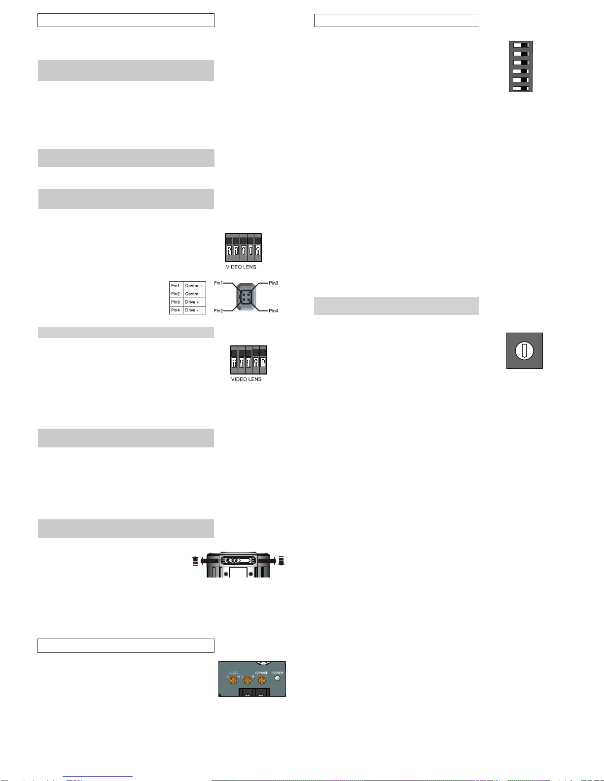
1. Video Auto Iris Lens Pin assignment
GND: Shield, ground.
+12V: Power source; +12VDC, 50 mA Max.
Video:Video signal output.
2. DC Auto Iris Lens
The 4 pin connection terminal is on the
rear panel. Refer to the pin assignment
to ensure the proper operation.
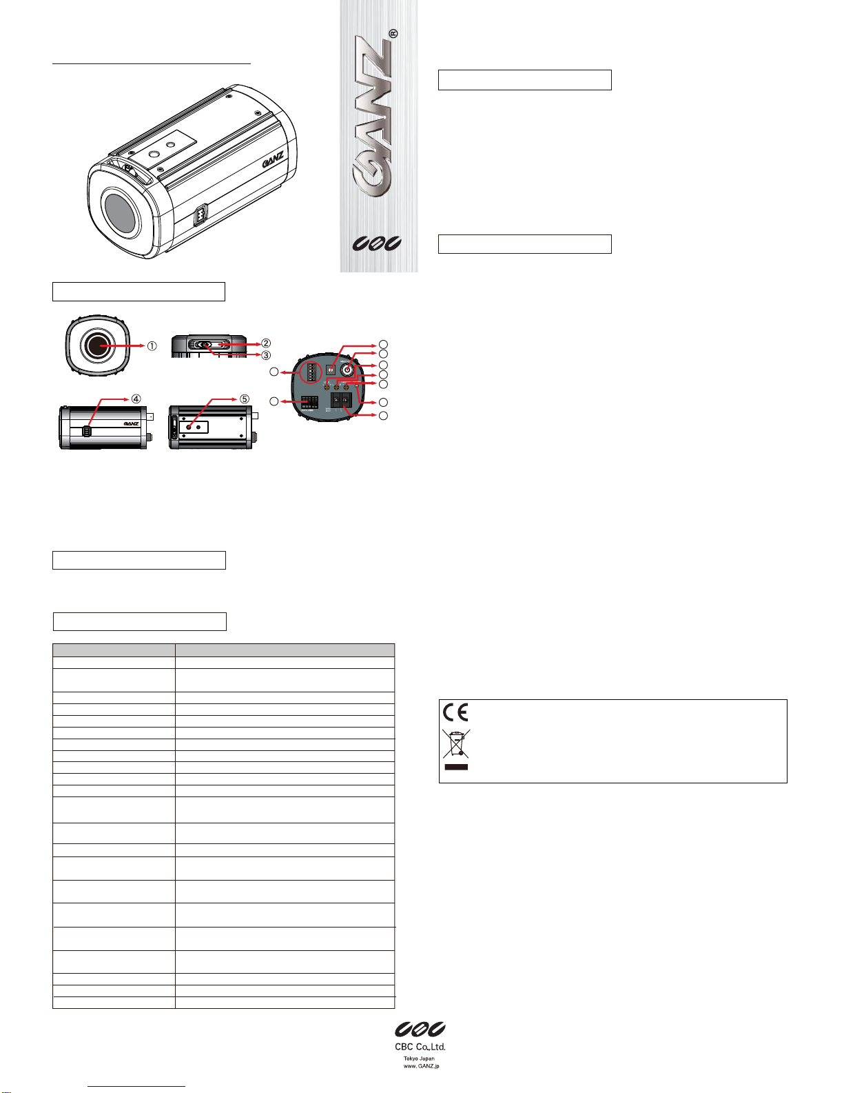
1. Mount a lens onto the camera lens mount. Turn the lens clockwise.
2. This camera can accept CS-mount lens, or C-mount lens with a 5 mm adaptor ring.
Cautions for lens mounting:
1. In case of using a lens heaver than the camera, the lens and camera will require
additional support.
2. Do not over-tighten the lens onto the camera mount.
3. Do not rotate the lens counter-clockwise.
Lens Mounting
→refer to PARTS DESCRIPTON (1)
CONNECTION AND ADJUSTMENT
Power Supply Cable Connection
→refer to PARTS DESCRIPTON (14)
Video Cable Connection
→refer to PARTS DESCRIPTON (9)
Auto Iris Lens Connections
→refer to PARTS DESCRIPTON (4) & (7)
GND
LAMP
This camera is equipped with an external contact terminal
in order to prevent a mechanical Optical Low pass
Filter hunting in infrared illumination.
Connecting it to GND immediately switches the mode
from daytime to nighttime.
Caution
When using an IR lamp, be sure to use an infrared compatible lens
(Day & Night lens) to ensure proper focusing in IR illuminated settings.
LAMP Contact Terminal
GND
+12V
VIDEO
POTENTIOMETER SETTING
TDN / HIGH
The TDN mode can be activated only when TDN switch is set to “ON”.
When set “HI”, the camera will switch to Night (Monochrome) mode
at a lower light level.
Shutter Speed Setting (MES)
→refer to PART DESCRIPTION (8)
You can select the manual shutter speed of
1/50, 1/120 FLK or 1/120 FLK, 1/250, 1/500, 1/1K, 1/2K,
1/4K, 1/10K, 1/100K seconds, or
Auto Electronic Shutter (AES).
Turn the switch to the to the Shutter parameter (1~9) and
select a desirable electronic shutter speed.
Set to “0” is for AES.
1
2
3
4
5
6
7
8
9
0
50/60 AES 100K
250
F.L.
4K
10K
Shutter Speed