ccei BRIO WPX30 Owner's manual

Technical instructions
WPX30
Underwater LED lighting
Réf : PF10R410
Table of Contents
1. Technical features .................................................................................................................. 2
2. Packaging Contents ................................................................................................................ 3
3. Description ............................................................................................................................. 3
4. Compatibility - Control .......................................................................................................... 4
5. Use - Autonomous mode ....................................................................................................... 5
6. Safety ..................................................................................................................................... 5
7. Installation ............................................................................................................................. 6
8. Electrical Connections ........................................................................................................... 8
9. Transformer power ................................................................................................................. 9
10. Projector Protection .............................................................................................................. 9
11. Cable section ...................................................................................................................... 10
A. Connection schematic ........................................................................................................ 11
B. Declaration of conformity ................................................................................................. 12
Read these instructions carefully before installing, commissioning and using
this product.
MPNT0126 v2.0EN (28/10/2016)

Technical instructions WPX30 v2.0EN
1. Technical features
Sizes ext. Ø 255mm (wall support)
Installation Wall mounting
Power supply 12 V ~ (AC) 50Hz/60Hz
Power consumed 40W maximum (according to colour)
Weight 1.2kg (projector+cable)/1.4kg (packaged)
LED type
9 powerful monochrome LEDs (3R/3G/3B)
+ 6 MidPower cool white LEDs 6000°K
Risk group 1 (low risk) according to IEC62471:2006
Protection index IP-68
Max. luminous flux According to colour/1150 lm maxi (white)
Color control By Brio-RC,Brio-RC+ or by toogle switch
Floodlights must never be turned on outside of water.
www.c-
cei.fr 2

Technical instructions WPX30 v2.0EN
2. Packaging Contents
1 BRIO WPX30 light with 3m cable and:
• 3 fixing screws + 3 wall plugs
• 1 wall support
• cable gland kit ref. MPPE0021
• O-ring kit
• Technical manual (this document)
3. Description
The WPX30 power LED lights are designed to replace pool projectors, traditionally fitted with
300W PAR56 incandescent bulbs. They are installed directly on the pool wall, with no niche being
required.
They come with powerful LED to improve the quality and reli-
ability of the lighting of your pool while reducing your energy
consumption.
The colours are created by mixing 3 primary colours: Red (R),
Green (G for "Green") and Blue (B) and adjusted by the lighting
of white LED (W for "White").
By adjusting the intensity of these four colours, it is possible to create more than 4 billion shades!
The addition of white sources will retain the advantages of RGB, and adds on those provided by
white LEDs. Besides the fact that an unbelievable number of colours can be provided, the forte of
the white is that it provides additional tones by the "pastel colouring" of colours
www.c-
cei.fr 3

Technical instructions WPX30 v2.0EN
4. Compatibility - Control
The BRIO WPX30 LED lights can operate autonomously with simple power cuts applied to the on/
off switch, or be controlled remotely using an RC system (Brio RC, MOD Brio RC or MeteoR with
OPT Brio RC), or a RC+ system (Brio RC+, MeteoR2) or by Power Line communication.
Beware, with a view to ensuring that your installation is compatible with the other projectors of the
BRIO range, please adhere to the following instructions. In the event of use:
• In autonomous or RC mode, only install the lights with RC compatible products.
• In RC+ mode, only install the lights RC+ compatible products.
Compatibility with the other products of the range
Mode RC (Brio RC,
MOD Brio RC, Me-
teoR + OPT Brio RC)
Mode RC+ (Brio
RC+, MeteoR2)
EOLIA WEX30
EOLIA WEX60 V04
EOLIA WEX100 V04
GAÏA GAX30
STELLA WPX30
ALICIA WJX15 V04
BRIO ZX30/60/100
MINI BRIO X15
EOLIA WEX30 V05
EOLIA WEX60 V05
EOLIA WEX100 V06
GAÏA GAX30 V03
STELLA WPX30 V04
ALICIA WJX15 V04
BRIO ZX30 V03
BRIO ZX60/ZX100 V02
MINI BRIO X15 V02
For any models whose version is not specified, all versions are concerned.
For any models whose version is specified, all greater versions are compatible.
Contact your reseller if you have any queries about compatibility before in-
stalling the equipment!
www.c-
cei.fr 4

Technical instructions WPX30 v2.0EN
5. Use - Autonomous mode
In the absence of a control unit, the lights operate autonomously and the user can choose between
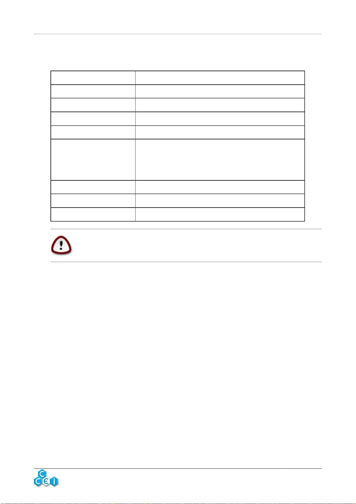
18 modes: 11 set colours and 7 programmes;
Mode Type Description
1 Set colour Pure white
2 Set colour Blue
3 Set colour Blue lagoon
4 Set colour Cyan
5 Set colour Violet
6 Set colour Magenta
7 Set colour Pink
8 Set colour Red
9 Set colour Orange
10 Set colour Green
11 Set colour Sea green
12 Sequence Quick "Rainbow"
13 Sequence Slow "Rainbow"
14 Sequence Procession of 11 set colours
15 Sequence Colourful psychedelic flashes
16 Sequence Blue/White/ Cyan
17 Sequence Random sequence 1
18 Sequence Random sequence 2
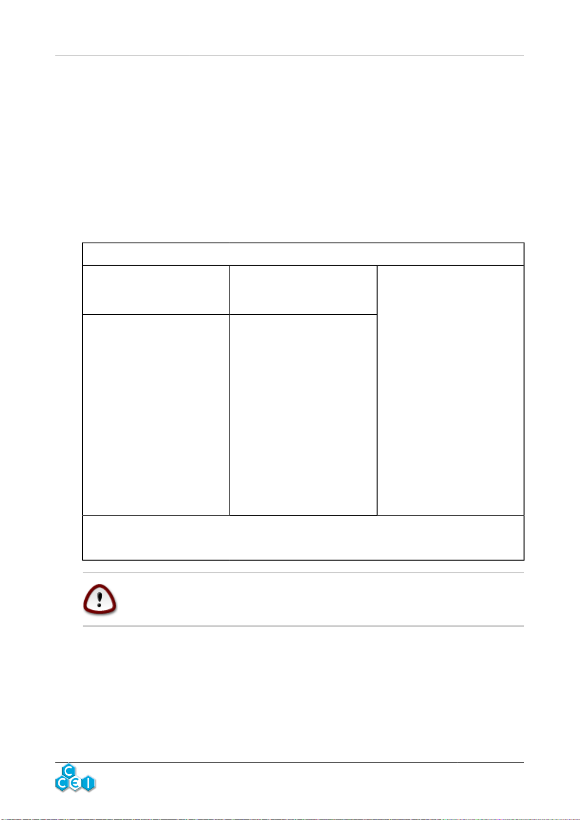
Change of mode
The mode can be changed by
cutting the power supply of the
lights for a very short space of
time (less than 1s).
By successive interruptions, it is
possible to display the 18 oper-
ating modes. After mode 18, the
WPX30 return to the first colour
(mode 1)
Reset
To reset the lights and take them
to mode 2 at the same time, the
power supply should be cut for
approximately 2s.
When the projector is started up
after a cut of several seconds
(more than 4s), the WPX30
loads back up in the mode dis-
played at the time it was last
shut down.
6. Safety
If the temperature inside the WPX30 is abnormaly high, a safety device shuts off the lighting and
produces a red flashing light. As soon as the normal temperature returns, the lights return to normal
working order.
www.c-
cei.fr 5

Technical instructions WPX30 v2.0EN
7. Installation
It is highly recommended to use the services of a professional for the installa-
tion.
The light is locked in the wall support using a bayonet system. The wall support must be fixed on
the wall. According to the type of the pool, there are various possible ways to fix the support.
Concrete + coating or tiles: The body of the cable gland A is sealed in concrete with its nut E. The
wall support is fixed directly on the wall using the 3 supplied screws* and plugs.
Concrete + liner: Seal the wall conduit B with its nut E in concrete and glue an O-ring F before
positioning the liner. Place then an O-ring F at the pool side and screw the cable gland A. The wall
support is fixed directly on the wall using the 3 supplied screws* and plugs.
One-piece pool: Screw the body of the cable gland A with an O-ring F at the pool side using the
nut E at the back of the wall. The wall support is fixed directly on the wall using the 3 supplied
screws* and plugs.
Panel + liner: Glue an O-ring F on the panel before placing the liner. Glue a second O-ring F at the
pool side after the positioning of the liner. The body of the cable gland A is screwed using a nut E
at the back. The wall support is fixed directly on the wall using the 3 supplied screws* and plugs.
www.c-
cei.fr 6

Technical instructions WPX30 v2.0EN
Wood: After making holes in the panel screw the support plaque G using the 4 supplied screws.
Mount the wall conduit B and fix it with the nut E. Glue an O-ring F on the panel before positioning
the liner. Glue a second O-ring F at the pool side after placing the liner. Screw then the body of the
cable gland A in the wall conduit B.
*It is advised to use silicone or any other sealant around the screws during
installation.
www.c-
cei.fr 7

Technical instructions WPX30 v2.0EN
8. Electrical Connections
Installation of this project involves a hazard of electric shocks. We strongly rec-
ommend you contract a professional installer. Incorrect installation places you
in danger and may irreversibly damage the product and the equipment con-
nected to it. In compliance with the NF C 15-100 standard, pool lights installed
in Volume 0 must always be powered by VLSV (Very low safety voltage). Al-
ways cut off the power upstream before handling the electrical installation.
Risk of electric shock. Only connect to a circuit which is protected by a cir-
cuit-breaker. If you are not sure if these types of devices are fitted, contact a
qualified electrician.
The electrical connection must be performed in a dry place. The cable glands in the connection box
must be tightened to avoid any water ingress.
Thanks to the body of the cable gland there are two con-
nection possibilities for the sheath at the back: either a tube
IRL diam. 20mm or female coupling 3/4". It is possible to
use a sleeve F/F 3/4" to mount a standard sheath for pool
lights.
The light is supplied with 3m cable. If the cable has to be
renewed it is possible to open the body at the backside of
the light for an access to the connection. The used cable
must be compatible with an extended immersion in pool
water and its diameter must fit with the screw of the cable
gland.
www.c-
cei.fr 8

Technical instructions WPX30 v2.0EN
9. Transformer power
The transformer to be used should have a sec-
ondary voltage of 12V (12.5V according to the
model). Its power should be in keeping with the
power of the lights to be connected.
At any rate, the sum of the powers of the lights
should remain below or equal to the power of the
power
Transformer power Max. no. of X30
50VA 1
100VA 2
300VA 7
Preferably use transformers sold in power supply units from the same manu-
facturer.
10. Projector Protection
Independent protection is necessary for each WPX30. Protection must be ensured in the secondary
of the transformer using fuses or breakers at 4A.
www.c-
cei.fr 9

Technical instructions WPX30 v2.0EN
11. Cable section
SECTION (mm²)
2.5 4 6 10
The drop in voltage in the power supply cable of the
WPX30 must be limited so that the colours are not al-
tered.
Respect the table opposite (one projector per cable); Max. length
(m) 10.0 17.0 25.6 42.6
www.c-
cei.fr 10

Technical instructions WPX30 v2.0EN
A. Connection schematic
www.c-
cei.fr 11

Technical instructions WPX30 v2.0EN
B. Declaration of conformity
Bleu Electrique SAS (FR47403521693) declares that the pro-
ductWPX30 meets the safety and electromagnetic compatibility re-
quirements of European Directives 2006/95/EC and 2004/108/EC.
Emmanuel Baret
Marseilles, on 28/10/2016
Distributor's stamp
Date of sale: . . . . . . . . . . . . . . . . . . . . . . . Batch N°: . . . . . . . . . . . . . . . . . . . . . . . . . . .
www.c-
cei.fr 12
This manual suits for next models
1
Table of contents
Other ccei Underwater Lighting manuals