CCTVMATE.COM LCD390 User manual

HD-TVI, Analogue & IP
CCTV Test Monitor
The LCD390 professional CCTV test monitor is
capable of testing, conguring and controlling
HD-TVI, analogue and IP cameras.
It features a full Qwerty keyboard, ONVIF 2
compatibility, a 1080p HD 4 inch screen and
up the coax control.
LCD390 Instruction
Manual
xLCD390 v1
Instruction
Manual

2For more information visit cctvmate.com
Introduction
The comprehensive LCD390 all-in-one CCTV test
monitor has been designed with CCTV installers in
mind so that it is as useful and user friendly as possible.
It’s compatible with HD-TVI, IP and analogue equipment
so you only need one device for all installs. It has a
full fold out Qwerty keyboard so networking and IP
addressing is a breeze. The built-in high power LED
torch comes in handy when working in dark loft spaces
and the 12V DC and POE outputs allow you to power
cameras when testing.
Safety Information
1. To obtain the maximum benets from the
CCTVmate LCD test monitor, it is recommended
that you read this manual before use.
2.
To ensure product longevity please do not use the
monitor outside of the following operating conditions:
•Operating temperature: -10 to 55ºC
•Humidity: 30 to 90%
3.
When
in use avoid unnecessary exposure to heat,
damp or dirt particularly around the connection
sockets.
4. Recharge this unit using adaptor supplied to
ensure overcharging does not occur and reduce
the life of the battery.
5. Do not disassemble this product or its parts.
6. In the event of an issue with this product, please
return to the outlet where it was purchased or
seek further advice at www.cctvmate.com

3Manual Ref: xLCD390
Contents
Key Features 4
Accessories 5
Connections & Controls 6
Keyboard 8
Basic Operation 9
Battery & Recharging 10
Powering Cameras 11
ONVIF Test 12
Analogue Camera Test & RS485 Control 21
Analogue Video Generator 24
RJ45 Cable TDR Test 26
Network Tools 28
Record Playback 31
Settings 32
Upgrading Firmware 34
Transferring Files Over FTP 35
Other Products To Consider 36
Specication 40
Menu Options

4For more information visit cctvmate.com
Key Features
TVI, IP & Analogue
The comprehensive LCD390 is capable of testing
TVI, IP and analogue equipment.
ONVIF 2 Compatible
Compatible with all the latest IP Cameras.
Coaxitron & RS485 Control
Congure and control compatible cameras via the
coax cable or an RS485 connection.
Network & Cable Testing
Easily troubleshoot problems and identify faults.
12V DC Output & POE
Power cameras during testing via a 2.1mm DC
connection or POE.
Full Qwerty Keyboard
Quick and easy IP addressing and networking.
Built-in Torch
Handy when working in dark environments such as
loft spaces.
Internal Storage For Saving Recordings
Store test recordings and images which can then be
transferred to a PC via USB.
1080p & 720p
Supports 720p and full 1080p HD images.
Lithium Ion Battery
Built-in high power rechargeable battery for
extended use.

5Manual Ref: xLCD390
Accessories (Included)
BNC - BNC Lead
Carry Case & Shoulder
Strap
Lanyard
Phono - BNC Connectors
USB - Mini USB Lead
Audio Test Lead Network (Patch) Lead
RS485 Test Lead
2.1mm DC Power Lead Spare Terminal Block
Power Supply Lead
POE Power Injector

6For more information visit cctvmate.com
Connections & Controls
No. Feature Primary Function
1 Power Indicator Lights green when on
2 Data Indicator Flashes red when data is
being transmitted
3
Charge Indicator
Lights red when charging /
O when fully charged
4 MODE Displays main menu
5 SET Display/Edit settings for
current operation
6 SCR Enter/Exit full screen mode
7 FOCUS PTZ focus + and - adjustment
8 ZOOM PTZ zoom + and - adjustment
9 IRIS PTZ iris + and - adjustment
+ Conrm / - Cancel changes
10 Arrow Keys PTZ movement / Navigation
Secondary functions
Some keys have various secondary functions. Specic
secondary functions are indicated on screen depending
on which operation is currently being performed.
31
2
4
7
8
5
6
9
10

7Manual Ref: xLCD390
Connections & Controls
No.
Feature Primary Function
1
High Power LED LED torch
2
BNC Video In HD-TVI & analogue video in
3
BNC Video Out HD-TVI & analogue video out
4
Network Port 1
(Blue)
Network port with POE output
Orange LED - POE indicator
Green LED - Data indicator
5
Network Port 2
(Green)
Network port with POE input
Orange LED - POE indicator
Green LED - Data indicator
6
Mini USB Port For connecting to PC
7
Audio Socket For audio testing
8
RS485 Output For RS485 testing & control
9
12V DC Output 12V / 2A Output for powering
CCTV cameras
10
Reset Button Push to factory reset device
11
Power Button /
Torch
Hold to turn device On/O
Quick double press to turn
torch On/O
1 12 3
5
4
8
9
10
11
6
7

8For more information visit cctvmate.com
Keyboard
Useful Keys & Indicators
Feature Function
Digital zoom +
and - in live view
and playback
Navigate around
image during live
view or playback
Feature Function
Take snapshot during
live view or playback
Video clipping Start &
Stop during live view
Space bar
Cancel text input
Backspace / Delete
Move to next text eld
Switch between upper
and lower case letters
Switch to symbol input
(Symbols indicated
in red)
Lights up when Caps
lock is on
Lights up when Symbol
lock is on
The full fold out Qwerty keyboard
is one of the LCD390s most useful
features and one which sets it
apart from most other CCTV test
monitors on the market.
Having a full keyboard as opposed
to a reduced or on screen keyboard
makes text input much easier
saving you time and eort.

9Manual Ref: xLCD390
Basic Operation
Turning The Device On/O
1.
To turn the device
On
press and hold the
Power
Button
’ until the
Power Indicator
lights up.
2.
To turn the device
O
press and hold the
Power
Button
until the screen turns o.
Selecting Functions
1.
To display the main menu press the ‘
Mode
’ button.
2.
Use the
Up
and
Down
arrow keys to highlight the
desired function.
3.
Use the
Right
arrow key to select function.
Connecting The Lanyard
1.
Slide one plastic buckle roughly 6 inches onto either
end of the lanyard.
2.
Pass one end of the lanyard through the hole in the
top left side of the test monitor, loop over and pass
back through the buckle. Repeat for the right side.
Audio Testing
1. Turn the test monitor on and plug the Audio Test
Lead into the 3.5mm Audio socket on the side of
the device.
2. Connect the Black clip of the Audio Test Lead to
the earth of the audio device and the Red clip to
the signal.
3. Any audio input will then play through the built-in
speaker on the rear of the test monitor.
Using The LED Torch
1. The LED torch can be turned on when the device
is switched On and O. To turn the LED torch On or
O quickly press the Power Button twice.
Note: The LED torch uses two ultra bright LEDs. Never
look directly at the LEDs as this may cause
damage to the eyes.
To conserve energy the torch automatically turns
O when the device is switched On or O.

10 For more information visit cctvmate.com
Battery & Recharging
Installation
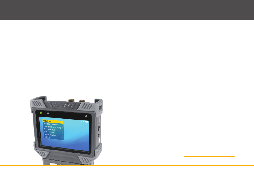
The LCD390 is supplied with a high capacity
Lithium-ion Polymer battery. For safety reasons the
battery is packaged separate to the test monitor.
To install the battery rst remove the battery cover
on the rear of the device. Insert the top of the battery
with the gold connectors pointing downwards and the
bottom of the battery should then drop into place.
Note:
When the battery is inserted the test monitor
will turn on automatically.
Recharging
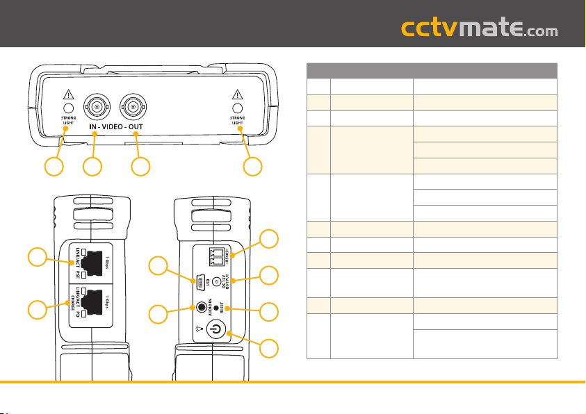
To recharge the battery you will need to connect the
power supply lead, POE injector and network lead
supplied with the test monitor as described below.
1.
Connect the power supply lead to the POE injector.
2.
Connect one end of the network lead to ‘
Data +
POE output
’ RJ45 socket on the POE injector.
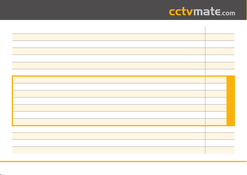
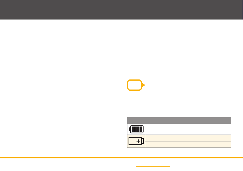
Battery Indicators
Icon Function
Displays the current battery level
Lights up red when charging
Flashes three times when battery is empty
3.
Connect the other end of the network lead to the
green RJ45 socket labelled ‘
Charge
’ on the side
of the test monitor.
4.
Plug the power supply lead into a wall socket and
turn the socket on.
5.
The orange light on the RJ45 socket and the red
battery light on the front of the device will light up
when charging.
TIP As the LCD390 is recharged via POE you can
recharge the device from any RJ45 socket
with a POE output such as a network switch
or an network socket on a NVR.

11Manual Ref: xLCD390
Powering Cameras
One of the most convenient features of the LCD390 is
the power output which allows you to power cameras
using the test monitor itself.
This is great when testing cameras where power cables
have not yet been installed or if you wish to take a
camera down so you're not testing up a ladder.
There are two options available for powering cameras,
either using the 12V DC output or via POE.
Powering Cameras Using POE
To power a POE compatible camera simply connect
an RJ45 patch lead such as the one supplied from the
camera to Network Port 1 (Blue).
Note:
The maximum POE output is 25.5W. If this is exceeded
the output will be terminated automatically.
Powering Cameras Using The 12V Output
To power a 12V DC camera connect the supplied
2.1mm DC Power Lead from the 12V DC output of the
LCD390 to the 12V DC input of the camera.
Note: The maximum 12V output is 2A. If this is exceeded
the output will be terminated automatically.
If a POE device is connected to Network Port 1 the
12V DC output will be disabled.

12 For more information visit cctvmate.com
ONVIF Test
The ONVIF Test is a three step process designed for
troubleshooting, conguring and controlling ONVIF
compatible cameras.
The comprehensive test allows you to view and
amend IP settings, perform Ethernet tests, discover
and congure IP cameras, view live images, control
PTZs and much more.
Connecting To Cameras & Networks
All connections for ONVIF testing are made using an
RJ45 patch lead.
When testing individual cameras these can be
connected to either network port 1 or 2 but only port 1
provides a POE output.
Note:
For more information on powering cameras using
the LCD390 see page 11 - Powering Cameras.
If you are connecting to a network switch this again can
be connected to either network port 1 or 2.
ONVIF Test 1: Ethernet & IP Testing
The Link Test displays various speeds, network
information and IP settings for connected devices.
TIP
When connecting to a POE compatible
network switch, using Network Port 2 (Green)
will recharge the test monitor while you
are testing. The PD light will turn orange
showing POE power is being received.

13Manual Ref: xLCD390
ONVIF Test
The blue information bar relates to Network Port 1 and
the green information bar relates to Network Port 2.
The grey bar displays the IP information. There are three
possible options, Static IP, DHCP request and DHCP server.
Link Speed
Shows the link speed of the connected device.
IP devices have three possible link speeds
10M, 100M or 1000M. This is followed by '
FD
'
(Full Duplex), meaning the connected device
can both send and receive information at the
same time or '
HD
' (Half Duplex), when the
connected device can only send or receive
information not both at the same time.
The message '
Link Down
' is displayed if no
connection can be established.
Packet Loss
Displays the success rate of data packets
being transmitted across the network.
Icon
Rate 100% 99% 98 to
95%
94%
or less
No
link
Ethernet Data Flow
Shows the current incoming and outgoing
Ethernet data ow in b/s, kb/s or mb/s.
Device Power
Shows what power is being supplied to the
camera connected to Network Port 1 (Blue).
12V Indicates the camera is receiving a 12V
DC input where as 48V indicates the camera is
being powered by POE.
POE Input
Shows what voltage is being supplied to the
test monitor via POE to Network Port 2 (Green).

14 For more information visit cctvmate.com
ONVIF Test
ONVIF Test 1: Choosing IP Mode
The LCD390 allows you to choose between static IP,
DHCP request and DHCP server. This can be set during
ONVIF testing as explained below.
DHCP Request
This is the default IP mode and the mode used when
connecting to and testing networks which support
DHCP (Dynamic Host Conguration Protocol).
To request an IP address for the test monitor press
the 'IRIS -' button on the front panel when in the 'Link
Test' screen. If successful the new IP address assigned
by the server will be displayed in the grey bar.
DHCP Server
This mode enables the LCD390 to act as a DHCP
server and can be used when connecting to DHCP
compatible devices and networks.
When connected, any device requesting an IP address
will be assigned one by the test monitor based on its
own IP address.
Static IP
To manually assign a static IP address to LCD390 press
the 'SET' button at the '
Link Test
' screen.
In this screen you will see a list of recently used IP
addresses and a list of commonly used IP addresses.

15Manual Ref: xLCD390
ONVIF Test
TIP
You can save your own commonly used IP
addresses by selecting an existing address
and pressing 'SET'. A much easier alternative
to repeatedly typing in the same IP address.
To create a new IP address press the '
SET
' button.
Input the IP address, Subnet mask and Gateway
using the fold-out keyboard and then press '
IRIS +
' to
conrm your input.
Note:
For more information on using the fold-out
keyboard see page 8.
Use the arrow keys to highlight an IP address then
press '
IRIS +
' to conrm your selection.
ONVIF Test 2: Discovering Cameras
The second step of the ONVIF Test is discovering and
conguring compatible cameras. When entering this
step the LCD390 will automatically search for ONVIF
cameras connected directly to the test monitor or on
connected networks.
The device list is populated if and when ONVIF devices
are discovered. The IP address and/or the device name

16 For more information visit cctvmate.com
ONVIF Test
are displayed along with a video snapshot (snapshot
only displays for compatible cameras and if authorisation
is not required). The Up and Down arrow key can be used
to scroll through the list of discovered devices.
If a device expected to appear does not show in the list
you can search again by pressing the '
FOCUS -
' button.
If a camera still doesn't appear it may not be responding
to the ONVIF request or the subnet settings may not
match those of the test monitor. If this happens you will
need to return to the 'Static IP' section on page 14 to
make sure the test monitor's local IP address is within
the same subnet as the camera.
If this also fails you can try manually adding the camera
as explained in the following section.
Adding Cameras Manually
To manually add a camera press the '
ZOOM -
' button.
When manually adding IP cameras you will need to know
the camera's full IP address and ONVIF service path.
At the 'Manual Add Camera' screen enter the
camera's URL then press the 'IRIS +' button to conrm.
TIP
After typing the camera's IP address you
can press the 'TAB' button to automatically
add '/onvif/device_service'.

17Manual Ref: xLCD390
ONVIF Test
TIP
You can press the 'FOCUS +' button to
open the 'Code Book'. The code book is a
list of common user name and password
combinations such as admin - admin. Use
the arrow keys to highlight a combination
and press 'IRIS +' select it. You can also
edit the available options and save your
own commonly used user name and
password combinations.
Video Snapshot & Information
Highlight the camera you wish to view and after a
few seconds a snapshot of the camera's video will be
displayed to the right of the camera list if supported.
Above the snapshot you will see the resolution, frame
rate and compression method of the camera's video.
Some cameras require authorisation and the message
'
Authorisation Required
' will be displayed. Press the
'
IRIS -
' button to enter the authorisation screen.
Enter the camera's user name and password then
press the '
IRIS +
' button to conrm.

18 For more information visit cctvmate.com
ONVIF Test
Here you can see camera information such as
rmware version, serial number and URL. Find and
change addresses, servers and ports, even reboot or
factory reset the camera.
Menu Item Available To View Or Edit
Camera Info
Manufacturer / Model /
Firmware Version
/ Serial Number / Hardware ID / URL
Scopes Name / Location / Hardware / Type /
Prole / Other
eth0
Type / MAC / Speed / DHCP / IP Address /
Mask / Zero Cong
Network
Host Name / Gateway / DNS Server /
NTP Server / DDNS Name / DDNS Type /
DDNS TTL
System Reboot / Factory Default / Discoverable /
HTTP Port / HTTPS Port / RTSP Port
Note:
Not all settings are available for every camera. The
available settings depend on the abilities of the
camera connected.
Camera Setup
The camera settings menu allows you to view and edit
important information and settings which are vital for
networking the camera.
To enter the camera settings menu highlight the
camera you want to congure and press 'SET'.

19Manual Ref: xLCD390
ONVIF Test
ONVIF Test 3: Video & PTZ Testing
The third and nal step of the ONVIF test is video and
PTZ testing. When entering 'Video & PTZ' the camera's
video will be displayed automatically. You can enter
full screen mode which allows for PTZ control by
pressing the 'SCR' button. To enter the camera prole
settings menu press the 'SET' button.
Full Screen Mode & PTZ Control
In full screen mode the camera's video is made as big
as possible whilst maintaining the correct image ratio.
The larger image makes it easier to achieve the desired
results when making zoom and focal adjustments.
You can also control PTZ cameras in full screen mode.
Use the arrow keys to move the camera and the
'
ZOOM + & -
' buttons to zoom in and out.

20 For more information visit cctvmate.com
ONVIF Test
Digital Zoom Control
When viewing the camera's video you can use keys
'
1
' and '
Q
' on the keyboard to zoom in and out
respectively. You can then use the '
E'
, '
S
', '
D
' and '
F
'
keys to move around the image.
The graphic in the bottom right hand corner shows
the zoom level and indicates which portion of the
screen you are currently viewing.
Volume Control
You can control the camera's audio volume using
the '
U
' and '
I
' keys on the keyboard. '
U
' decreases the
volume and '
I
' increases the volume.
Prole Settings
The '
Prole Settings
' menu allows you to congure
the camera's mainstream and substream. You can set
the resolution, bitrate, framerate and more. To choose
which stream is displayed simply highlight it and
press '
FOCUS +/-
'.
Network Protocols
You can switch between '
TCP
' and '
UDP
' protocols
using the '
FOCUS +/-
' button.
TIP
TCP is a slower but reliable connection
ideal for slower networks. UDP produces
the best images with a fast connection but
could be unstable on slower networks.
Table of contents
Other CCTVMATE.COM Test Equipment manuals