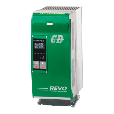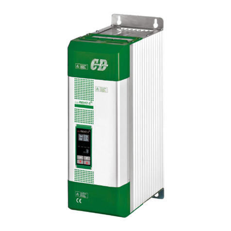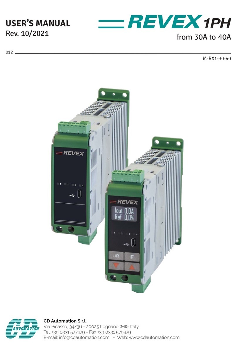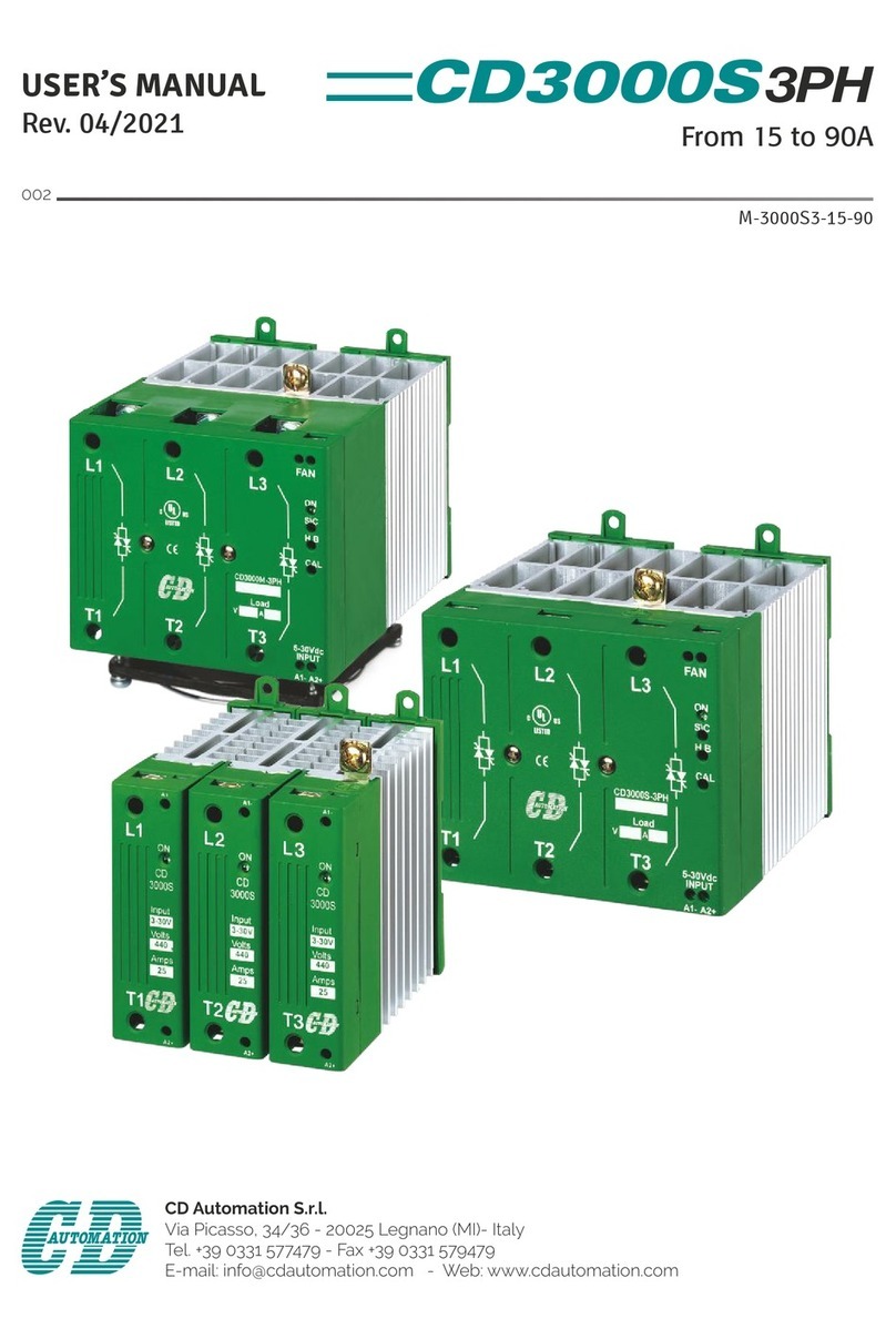
CD Automation srl REVO M User’s Manual
CD-Eng-REVO-M-3PH-30-40A-Thyristors-Units
1 IMPORTANT WARNINGS FOR SAFETY __________________________________________6
2 NOTE ___________________________________________________________________7
3 INTRODUCTION ___________________________________________________________8
4 ADVANTAGES COMPARED WITH ANALOG THYRISTOR UNIT _________________________8
5 SOFTWARE CONFIGURATOR CDA THYRISTOR CONFIGURATOR SOFTWARE _____________9
6 QUICK START ____________________________________________________________10
7 BASIC CONNECTIONS AND SIZING ___________________________________________11
8 IDENTIFICATION AND ORDER CODE __________________________________________12
8.1 Identification of the unit ______________________________________________________12
8.2 Order Code ________________________________________________________________13
9 TECHNICAL SPECIFICATIONS _______________________________________________14
9.1 General features: ___________________________________________________________14
9.2 Input features: _____________________________________________________________14
9.3 Output features(power device): ________________________________________________14
10 INSTALLATION __________________________________________________________15
10.1 Environmental installation conditions ___________________________________________15
10.2 Derating Curve ____________________________________________________________15
10.3 Dimensions and Weight _____________________________________________________16
10.4 Fixing holes _______________________________________________________________16
11 WIRING INSTRUCTIONS __________________________________________________17
11.1 Access to L1-L2-L3 and T1-T2-T3 terminal Screw _________________________________18
11.2 Command Terminals ________________________________________________________19
11.2.1 Terminal block M2 _______________________________________________________________________ 19
11.2.2 Terminal block M1 _______________________________________________________________________ 19
11.2.3 Terminal block M3 _______________________________________________________________________ 19
11.2.4 Terminal block M4 _______________________________________________________________________ 19
11.3 Schematic ________________________________________________________________20
11.4 Connection Diagram for Single-phase___________________________________________21
11.5 Connection Diagram for 3 phases (control on 3 phases) ____________________________22
12 CONTROL PANEL_________________________________________________________23
12.1 Scroll the parameters _______________________________________________________24
12.2 Operator Menu ______________________________________________________25
12.3 Setup Menu __________________________________________________________28
12.4 Hardware Menu _____________________________________________________31
12.5 Control Panel Led __________________________________________________________33
12.6 Displayed Alarms __________________________________________________________33
13 INPUT OUTPUT SIGNAL ___________________________________________________34
13.1 Digital Input ______________________________________________________________34
13.1.1 Start/Stop (Terminal 3 of M2) ______________________________________________________________ 34
13.1.2 Configurable Input (Terminal 4 of M2) ________________________________________________________ 34
13.2 Digital Output terminal (terminal 14-15-16 of M1)_________________________________34
