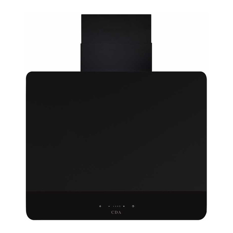
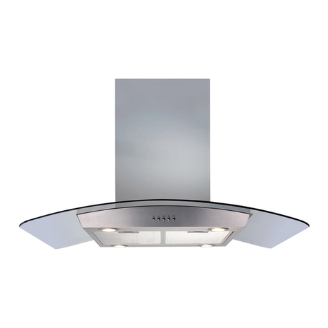
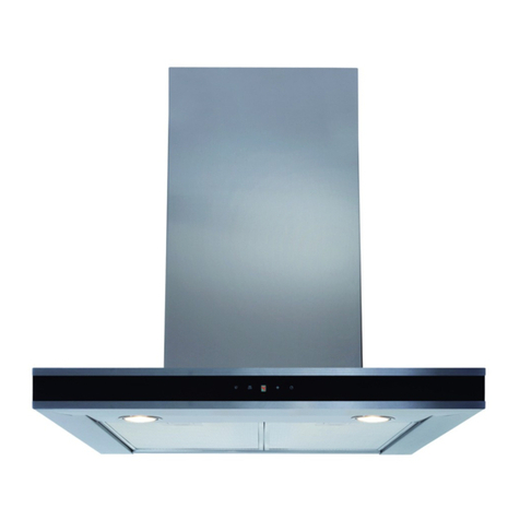
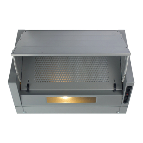
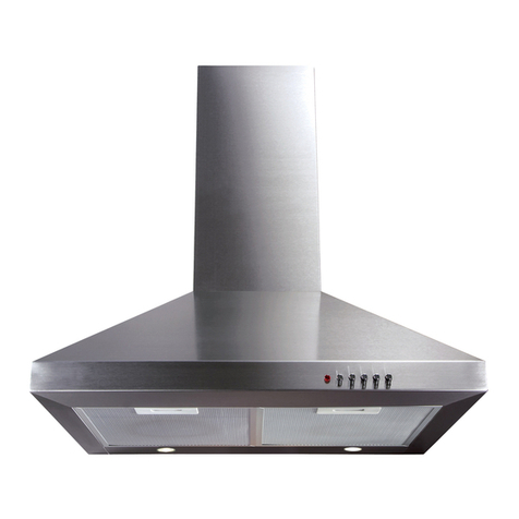
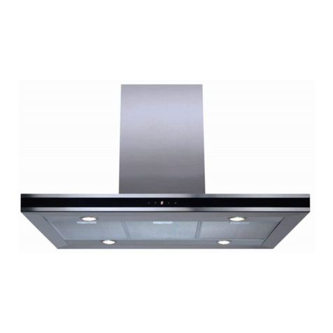
CDA CCG Service manual

CCG
Built-in extractors
Installation, use and maintenance


2| Instruction Manual
Contents
3. Important
4. Declaration of Conformity
product disposal
5. Notes
6. Operation
9. Care and maintenance
Removing and cleaning the grease filters
Changing a charcoal filter
11. Extractor lighting
11. Notes on operating modes
12. Mains electrical connection
13. Electrical information
14. Fixings provided
14. Product dimensions
16. Installation steps
Ducting and ventilation
17. Energy Eciency Information (product fiche)
18. Notes page

Instruction Manual | 3
Important
The CDA Group Ltd cannot be held responsible for injuries or
losses caused by incorrect use or installation of this product.
Please note that CDA reserves the right to invalidate the
guarantee supplied with this product following incorrect
installation or misuse of the appliance or use in a commercial
environment.
This appliance is not designed to be used by people
(including children) with reduced physical, sensory or
mental capacity, or who lack experience or knowledge
about it, unless they have had supervision or instructions on
how to use the appliance by someone who is responsible
for their safety.
Under no circumstances should any external covers be
removed for servicing or maintenance except by suitably
qualified personnel.
Appliance information
Appliance model
Serial number
Please enter the details on the appliance rating plate below for
reference, to assist CDA Customer Care in the event of a fault with
your appliance and to register your appliance warranty.

EU Declarations of Conformity
This appliance has been designed and manufactured to comply with
all applicable UK and EU legislation,
Low voltage Directive, 2014/35/EU
Electromagnetic compatibility Directive, 2014/30/EU
ErP Directive, 2009/125/EC
RoHS Directive, 2011/65/EU
and has been marked with the following symbols.
IMPORTANT INFORMATION FOR CORRECT DISPOSAL OF THE
PRODUCT IN ACCORDANCE WITH EU DIRECTIVE 2012/19/EU.
At the end of its working life, the product must be taken to a special
local authority waste collection site, or to a dealer providing appliance
recycling services.
Disposing of a household appliance separately avoids possible
negative consequences for the environment and health. It also
enables the constituent materials to be recovered, saving both
energy and resources. As a reminder of the need to dispose of
household appliances separately, the product is marked with a
crossed-out wheeled dustbin.
4| Instruction Manual

Under no circumstances should the extractor be connected to any
gas ventilation system, flue system or hot air ducting system.
Do not vent the extractor into an attic or loft space.
Only house the extractor in rooms with adequate ventilation.
Remember that the extractor is powerful and whatever air is
extracted needs to be replaced.
Do not tile the extractor in. It should be removable for service or
maintenance.
Do not use silicone sealant to secure the hood to the wall.
You must be able to isolate the extractor from the mains electrical
supply after installation.
This extractor has been designed to be used in a room with a volume
of less than 36m³.
Steam cleaners must not be used when cleaning this appliance.
The performance of your extractor will vary depending on several
factors. These include type of extraction, length of ducting, room
volume, ventilation available and cleanliness of the filters.
The extractor should be cleaned regularly to prevent build-up of
grease. We recommend cleaning both inside and outside the
appliance monthly. Failure to observe the requirements specified
in this manual can result in a fire risk.
Please note
Instruction Manual | 5

OPERATION
Cooker hood controls
Control Panel is shown below:
3
4 5
81b
7 6
21a
Low speed ( 1 ). Use this speed when cooking a little food with hardly
any fumes.
Medium speeds ( 2 - 3 ). Use this speed when cooking multiple dishes
at the same time with moderate amount of fumes.
Turbo ( ) — use this speed when frying or grilling with large amount
of fumes. Attention! The Turbo mode is active only for 5 minutes (the
dot on the display flashes), after this time the gear will automatically
reduce to a lower level.
The appliance is fitted with gesture control sensors (1a, 1b, 2) and a
display (8) .
The control panel features touch controls: Control functions are
described below:
3- 15min Timer
4- Reduce fan speed
5- Increase fan speed
6- Gesture control on/o
7- Light control
After connecting the appliance to the power supply, all indicators will
light up for a brief moment and the display will also show . Then all
indicators and the display will go out, only the gesture control sensor
is illuminated on the control panel. The hood will enter standby mode,
which is indicated by a dot on the display.
When activated, touch to start the fan.
Available fan speeds:
•
•
•
6| Instruction Manual

O-Timer
Gesture control
Use the and sensors to increase or reduce fan speed.
Note! Turbo mode is only active for 5 minutes, then fan speed is
reduced automatically to one level down.
To turno the fan, touch repeatedly until fan speed is reduced to
zero .
Touch to turn on / o the lighting.
Use O-Timer to turn o the hood after a specified time. Use O-Timer
to filter the fumes out of the air after cooking. Touch to activate the
O-Timer at any time. The appliance will automatically turn o after
approximately 15 minutes.
When you plug in your appliance, gesture control is active and
indicator is on. Touch to turn o the gesture control. Touch
again to reactivate gesture control.
You can use gestures to control the fan speed and lighting. When
gesture control is active, you can also control the appliance using the
touch sensors.Gesture control works correctly when you move your
open hand about 5–10 cm from the surface of the control panel.
Note: To adjust the fan speed you need to move your hand across the
sensors as shown on Figure 4, items 1a and 1b. The area over which to
move your hand is marked on the figures presented below in this
manual.
If activating a certain function (such as turbo speed) requires multiple
hand gestures, reposition your hand for another gesture away from the
control panel to avoid triggering the motion sensors). Hand movements
must not be too fast. Preferably, a single gesture should take about 1
second.
Instruction Manual | 7

To turn o the fan or reduce
fan speed, move your hand
from right to left several times
in standby mode until the
display shows . Move your
hand one more time and the
appliance will turn o (gesture
control will still be active)
To activate the appliance,
move your hand across the
sensors from left to right. The
display will show .
To turn on the fan or increase
fan speed, move your hand
from left to right several times
in standby mode. The display
will show the current fan speed
after each hand gesture.
To turn the lighting on or o,
hover your hand about 10 cm
above sensor 2.
8| Instruction Manual

Fig 2.
Cleaning
You should use a non-abrasive cleaner. Any abrasive cleaner (including
Cif) will scratch the surface and could erase the control panel markings.
You can clean your extractor eectively by simply using a dilute solution
of water and mild detergent and drying to a shine with a clean cloth.
Ensure that the extractor is dry after cleaning.
Cleaning the grease filter
The grease filter should be kept clean to minimise the risk of fire. At
least once a month you should remove and clean the grease filter with
hot soapy water. You can also wash the grease filter in a dishwasher,
ensuring that you place it in an upright position to prevent damage from
other items in the dishwasher. After rinsing and drying, replace the filter.
Please note that cleaning the grease filter(s) in a dishwasher may cause
the filters to discolour. This is normal and does not constitute a fault with
the appliance.
Removing the grease filter
To remove the grease filter, pushing
the button on the handle and then
pull down on the filter at the front, as
shown in figure 2. Once released at
the front it can be pulled completely
away.
Instruction Manual | 9

Fig 3.
Changing the charcoal filter
To ensure the best performance of your extractor, you should replace
the charcoal filter every three to six months, depending on the
frequency of use and the style of cooking. To attach new charcoal
filters, first remove the grease filter(s) as described on the previous
page. Oer up the charcoal filters to the sides of the motor as shown in
figure 3, turning it clockwise until it locks in place.
Please note thatcharcoal filters are only required when the extractor is
being used in recirculation mode. Charcoal filters are not supplied and
are available to purchase from our Customer Care team.
10 | Instruction Manual

Operating modes
Note that when used in recirculation mode, the extractor will only
remove grease and odours from cooking. It will not remove steam.
Fig 4. Fig 5.
Filter
Extraction mode
(ducted outside) Recirculation mode
(no ducting)
Your extractor can be used in either of two modes - recirculation or
extraction. The choice often depends on the specific installation
requirements. Your installer will be able to advise which is best for you.
Instruction Manual | 11
Extractor lighting
The lighting on your extractor uses energy ecient LED technology
and is designed to last the lifetime of the product. If the LED system
malfunctions, please contact CDA Customer Care.
The LED units must only be replaced by
a competent appliance service engineer.

Mains electricity connection
THIS APPLIANCE MUST BE CONNECTED TO THE MAINS SUPPLY
BY A COMPETENT PERSON, USING FIXED WIRING VIA A DOUBLE
POLE SWITCHED FUSED SPUR OUTLET AND PROTECTED BY A
3A FUSE.
We recommend that the appliance is
connected by a qualified electrician,
who is a member of the N.I.C.E.I.C. and
who will comply with the I.E.T. and local
regulations.
The wires in the mains lead of this
appliance are coloured in accordance
with the following code:
BLUE = NEUTRAL, BROWN = LIVE, GREEN & YELLOW = EARTH
Fig 6
As the colours of the wires in the mains lead for the appliance may
not correspond with the coloured markings identifying the terminals
connecting to the fused spur, proceed as follows:
The wire which is coloured green& yellow must be connected to the
terminal marked E (Earth) or coloured green.
The wire which is coloured blue must be connected to the terminal
marked N (Neutral) or coloured black or blue.
The wire which is coloured brown must be connected to the terminal
marked L (Live) or coloured red or brown.
If the mains cable of this appliance is damaged, it must only be
replaced by a CDA approved service engineer, agent, or other
suitably qualified person.
12 | Instruction Manual

Electrical Information
IMPORTANT – ONLY USE A 3 AMP FUSE
The use of a 13A fuse can cause internal wiring damage whichwill not
be covered under the CDA warranty.
Do not mount the electrical isolation switch behind the chimney section.
It is a requirement that you must be able to isolate the extractor from
the mains electrical supply after installation.
Rated voltage (mains electrical voltage): 230 – 240Vac, 50Hz
Rated input (rated power consumption): 95W
Motor input: 90W
Lamp power: 1 x 5W
Troubleshooting
If your extractor is not working
1. Check that the mains electrical supply has not been switched o.
2. Check that the fuse in the spur has not blown.
3. Contact CDA Customer Care.
Instruction Manual | 13

Determining the position of your extractor
When the extractor is to be
mounted above an electric hob,
the distance between the hob
and the extractor must be
greater than 600. When the
extractor is to be mounted
above a gas hob, the distance
between the hob and extractor
must be greater than 700mm.
h = min 600mm
Fig 7.
h = min 700mm
If the instructions provided with your gas hob dictate that the required
distance between hoband extractor must be greater than 700mm
then that is the distance that should be observed; this is a legal
requirement and failure to comply with the regulations may lead to
your hob being disconnected from the mains gas supply, and the
installation reported to RIDDOR. Any heights measured are from the
ttoopp ooff tthhee ggaass bbuurrnnererss..
In tIn thhee aabbsseencncee ooff aannyy iinnssttruruccttiioonnss ssuupplipplieedd wwiithth tthhee ggaass hhoobb,, tthhee
mmiinniimmuumm disdisttaannccee bbeettwweeeenn tthhee hhoobb aanndd eexxttrraaccttoorr mmuusstt bbee aatt lleaeasstt
776600mmmm.. TThhee wwididtthh ooff aannyy hhoobb mmuusstt nnoott bbee ggreareatteerr ththaann tthhee wwiiddtthh
oof tf thhee exexttraraccttoorr..
14 | Instruction Manual

Installation
Fixings provided
We have provided a set of fixings that are suitable for most walls.
However, please ensure that the fixings you use to secure the
extractor to the wall are appropriate for the type of wall in your
kitchen.
Product dimensions
Installation
Fixings provided
We have provided a set of fixings that are suitable for most walls.
However, please ensure that the fixings you use to secure the
extractor to the wall are appropriate for the type of wall in your
kitchen.
Product dimensions
Fig 8.
Instruction Manual | 15

Installation steps
1. Drill 4 X Φ5mm mounting holes in the top plate of the cabinet and
open Φ160 mm air out let.
2. Use 4*35 mm phillips head screw and 4 washer ( Φ6.1 * Φ13 * 1 )
to fasten hood body.
For best performance and quietest operation, we recommend the use
Ducting and ventilation
of 150mm ducting and for the extractor to be used in extraction mode
(as shown in figure 4). 125mm ducting may be used but this will reduce
the performance and increase the noise of the extractor when in use.
The use of 100mm ducting is not recommended.
Wherever possible, utilize rigid circular or rectangular section pipe
which has a smooth interior, rather than the expanding concertina type
ducting. The lengths of ducting with minimal eect on performance are
as follows:
4metres with 1 x 90obend
3metres with 2 x 90obends
2metreswith 3 x 90obends
16 | Instruction Manual

Longer ducting can be used, but this will reduce the performance and
eciency of your extractor. Ducting should be sealed to the vent outlet
using suitable securing means. Note that ducting components and
ducting kits are optional accessories and must be purchased separately.
Installation for recirculation
When installing this extractor for recirculating the air within your kitchen,
we recommend the use of optional charcoal filters to help remove
cooking odours. You should change these every three to six months,
depending on use.
Product fiche (Technical information)
Model identification, Symbol
Annual Energy Consumption, AEC hood
Energy Eciency Index, EEI hood
Fluid Dynamic Eciency, FDE hood
Fluid Dynamic Eciency Class
Lighting Eciency, LE hood
Lighting Eciency Class
Airflow rate, min
Airflow rate, max
Grease Filter Eciency, GFE hood
Grease Filter Eciency Class
Power consumption in standby, Ps
Power consumption o mode, PO
Noise level at min / max, LWA
Noise level on boost
Units
kWh/yr
Lux/W
m3/h
m3/h
%
W
W
dBA
CCG60BL
39,6
A
30,4
A
22,6
B
218
540
78
C
0
0.43
66
-
Instruction Manual | 17

To determine the results, and in accordance with the requirements in relation to
the labelling of energy-related products and regarding the eco-design requirements,
the following calculations and measurement methods were applied:
Directive 2010/30/EU, REGULATION NO 65/2014.
Directive 2009/125/EC, REGULATION NO 66/2014.
EN 50564 — Electrical and electronic household and office equipment,
measurement of low power consumption.
EN 60704-2-13 — Test methods for the determination of airborne acoustical
noise, particular requirements for range hoods.
EN 61591 — Household range hoods and other cooking fume extractors –
methods for measuring performance.
Notes
18 | Instruction Manual

The CDA Group
Harby Road
Langar
Nottinghamshire
NG13 9HY
Sales Department
Phone: 01949 862010
Email: [email protected]
Customer Care
Phone: 01949 862012
Email: [email protected]
This manual suits for next models
1
Table of contents
Other CDA Scrubber manuals

CDA
CDA EVX110 Quick start guide

CDA
CDA ECH Reference manual

CDA
CDA CCA51 Quick start guide

CDA
CDA EVPK90 Reference manual

CDA
CDA EKP Quick start guide

CDA
CDA CCH60BL Installation and operating instructions

CDA
CDA EVC41 User manual

CDA
CDA ECP Reference manual

CDA
CDA EXA60 Quick start guide

CDA
CDA 3B10 Quick start guide

CDA
CDA EVP61 Quick start guide

CDA
CDA EVQ7 Reference manual

CDA
CDA EZT90BL Quick start guide

CDA
CDA ECHK90 Quick start guide
CDA
CDA ECH91BL Service manual

CDA
CDA EKPK90 Specification sheet

CDA
CDA EIN Series Reference manual

CDA
CDA EVX100 Reference manual

CDA
CDA EVCK41 Quick start guide

CDA
CDA ECPK91 Installation and operating instructions