CDA EXG60BL User guide

EXG60BL
EXG90BL
Gesture control extractor hood
Use and maintenance

2| Instruction Manual
Contents
3 Important information
5 Using your extractor
6 Touch controls
6 Lighting
6 O-Timer
7 Gesture controls
10 Cleaning and maintenance
11 Changing the charcoal filter
12 Changing the light
12 Ducting and ventilation
13 Installation
18 Mains electrical connection
19 Troubleshooting

Instruction Manual | 3
Important information
The CDA Group Ltd cannot be held responsible for injuries or
losses caused by incorrect use or installation of this product.
Please note that CDA reserve the right to invalidate the guarantee
supplied with this product following incorrect installation or misuse
of the appliance or use in a commercial environment.
This appliance is not designed to be used by people (including
children) with reduced physical, sensorial or mental capacity, or
who lack experience or knowledge about it, unless they have
had supervision or instructions on how to use the appliance by
someone who is responsible for their safety.
Under no circumstances should any external covers be removed
for servicing or maintenance except by suitably qualified personnel.
Appliance information:
Please enter the details on the appliance rating plate below for
reference, to assist CDA Customer Care in the event of a fault with
your appliance and to register your appliance for guarantee
purposes.
CE Declarations of Conformity:
This appliance has been manufactured to the strictest standards
and complies with all applicable legislation, including Gas
safety, Electrical safety (LVD) and Electromagnetic interference
compatibility (EMC).
Appliance Model
Serial Number

4| Instruction Manual
IMPORTANT INFORMATION FOR THE CORRECT DISPOSAL OF
THE PRODUCT IN ACCORDANCE WITH EC DIRECTIVE 2002/96/
EC.
At the end of its working life, the product must be taken to a
special local authority waste collection centre or to a dealer
providing appliance recycling services.
Disposing of a household appliance separately avoids possible
negative consequences for the environment and health. It also
enables the constituent materials to be recovered, saving both
energy and resources. As a reminder of the need to dispose of
household appliances separately, the product is marked with a
crossed-out wheeled dustbin
Please note:
Under no circumstances should the extractor be connected to
any gas ventilation system, flue system or hot air ducting system
Do not vent the extractor into an attic or loft space
Only house the extractor in rooms with adequate ventilation.
Remember that the extractor is powerful and whatever air is
extracted needs to be replaced
Do not tile the extractor in. It should be removable for service or
maintenance
You must be able to isolate the extractor from the mains electrical
supply after installation
Steam cleaners must not be used when cleaning this appliance.
The performance of your extractor will vary depending on a
number of factors. These include: type of extraction, length of
ducting, room volume, ventilation available and cleanliness of the
filters
Instruction Manual | 5
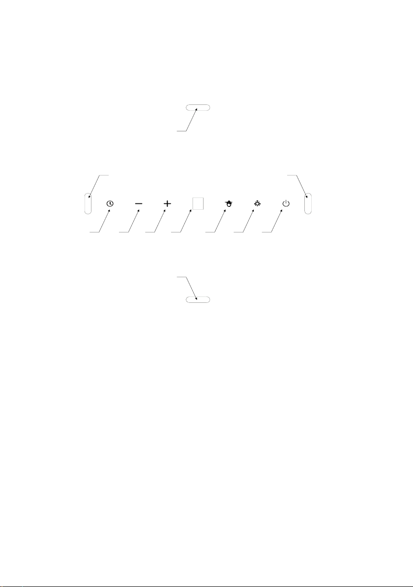
Using your extractor
C
B
A
D E F G
A
HI
B
A- Gesture sensors for turning the light on/o
B- Gesture sensors for fan speed
C- Timer sensor
D- Reduce fan speed sensor
E- Inscrease fan speed sensor
F- Display
G- Gesture control on/o sensor
H- Light sensor
I - On/o sensor
For best performance, you should switch on the extractor 15
minutes before starting cooking and for approximately 15 minutes
after cooking.
6| Instruction Manual
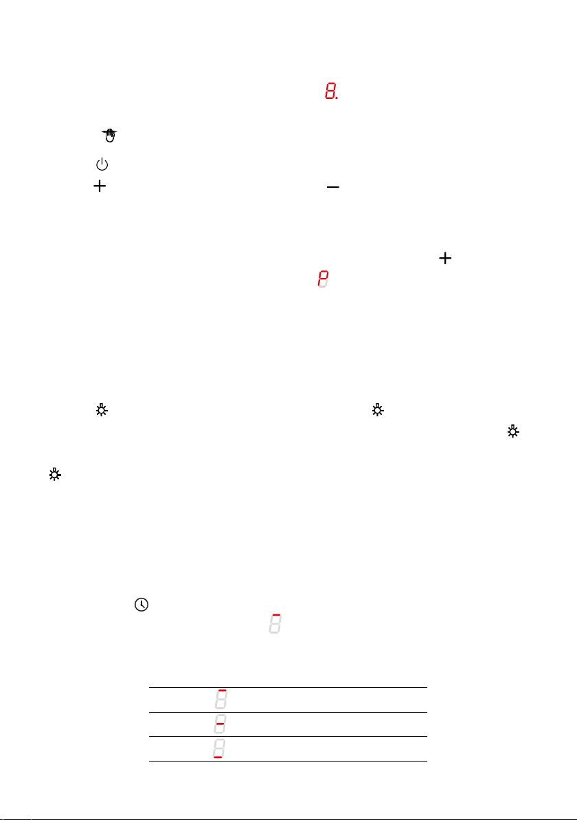
Touch controls
When the appliance is first plugged in, will briefly show on the
display and then the display will go o. Only the gesture control
sensor will be illuminated.
Touch to switch the appliance on. Once the appliance is on,
touch to increase the fan speed and to decrease the speed.
the fan speeds start with the lowest at 1 and the highest at 3.
There is a turbo function which can be activated for a maximum
of 5 minutes at a time. When at fan setting 3, touch the to enter
turbo mode and the display will show and a dot will flash. After
5 minutes the fan speed will revert to setting 3 and the dot on the
display will disappear.
Lighting
Touch to turn on the bottom lighting. Touch a second time to
turn on the decorative lighting at the top of the appliance. Touch
a third time and all lighting will go out. Alternatively, touch and hold
for 2 seconds and both sets of lights will turn on.
O-Timer
The O-Timer can be used to automatically turn the appliance o
after a specified time. The O-Timer can be set to 5, 10 or 15 min-
utes. Touch to activate the O-Timer at any time. The sensor will
flash and the display will show . Now use the _and +sensors to
select the O-Timer delay:
Display indication Delay time (Min)
15
10
5

Instruction Manual | 7
Touch to confirm your O-Timer setting (according to the table
on the previous page). A flashing dot will appear by the fan speed
on the display and the sensor will flash. Touch to deactivate
the O-Timer at any time, the dot by the fan speed and the will
stop flashing.
Gesture controls
When you plug your appliance in the gesture control is active and
the indicator is illuminated. Touch to turn o gesture control.
Touch again to reactivate gesture control.
You can use gesture controls to control the fan speed and lighting.
You can continue to use the touch sensors even if the gesture
control function is active.
For best performance, the gestures should be made approximately
5cm from the surface of the control panel.
When activating a certain function (such as turbo speed) requires
mutliple hand gestures, reposition your hand for another gesture
away from the control panel to avoid triggering the motion sensors
accidentally. Hand movements should not be fast, typically a single
gesture should take about 1 second.
Please see the next pages for gestures and their functions.
8| Instruction Manual
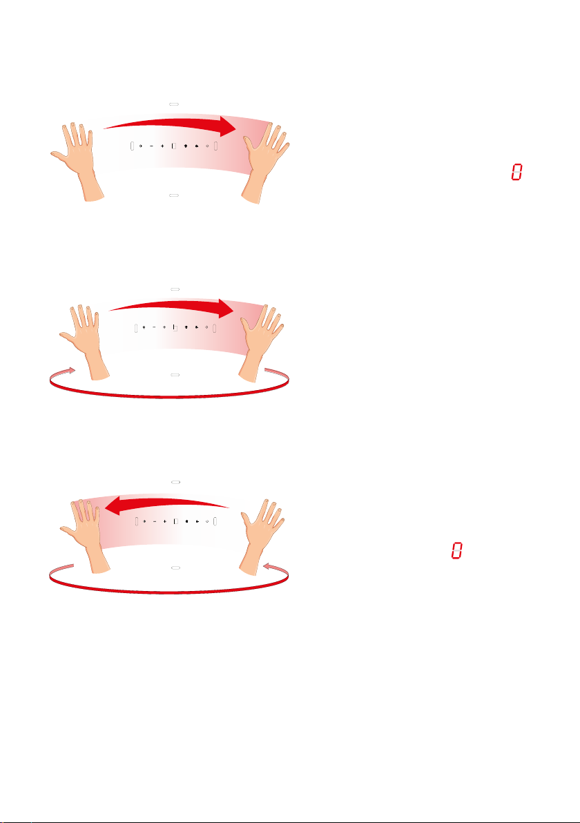
Gesture controls - Fan speed
To activate the appliance,
move your hand from left to
right. the display will show
To turn on the fan or increase
the speed, move your hand
from left to right several
times. The display will show
the current fan speed after
each gesture
To turn o or reduce the fan
speed, move your hand from
right to left several times until
the display shows . Move
your hand one more time
and the appliance will turn
o. The gesture control will
still be active
Instruction Manual | 9
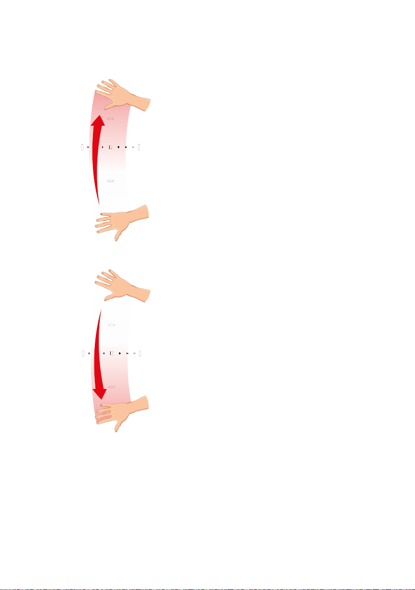
Gesture controls - Lighting
Move your hand from the
bottom of the control panel
to top of the control panel
to turn on the lighting. Move
your hand from the bottom
up to the top once more and
the decorative lighting will
also turn on
Move your hand from the top
of the control panel to the
bottom of the control panel
as many times as required to
turn o the lighting

10 | Instruction Manual
Cleaning and maintenance
IMPORTANT: DO NOT PERFORM MAINTENANCE OR CLEAN-
ING OF THE EXTRACTOR WITHOUT FIRST SWITCHING OFF
THE ELECTRICITY SUPPLY.
Cleaning
You should use a non-abrasive cleaner. Any abrasive cleaner
(including Cif) will scratch the surface and could erase the control
panel markings.
You can clean your extractor eectively by simply using a dilute
solution of water and mild detergent and drying to a shine with a
clean cloth.
We recommend always wearing PPE (Personal Protective
Equipment) when carrying out any cleaning or maintenance.
IMPORTANT:
•Steam cleaners must not be used when cleaning this
appliance.
•Once care and maintenance is complete, ensure that all parts
are correctly replaced before using the extractor.
Cleaning the grease filter
The grease filters should be kept clean to minimise the risk of fire.
At least once a month you should remove and clean the grease
filters with hot soapy water. You can also wash the grease filters in
a dishwasher, ensuring that you place it in an upright position to
prevent damage from other items in the dishwasher. After rinsing
and drying, replace the filters.
This manual suits for next models
1
Table of contents
Other CDA Ventilation Hood manuals


