5cdvigroup.com
EN
BO600RP - BO600RH
Vertical & Horizontal retrofi t housing
INSTALLATION MANUAL
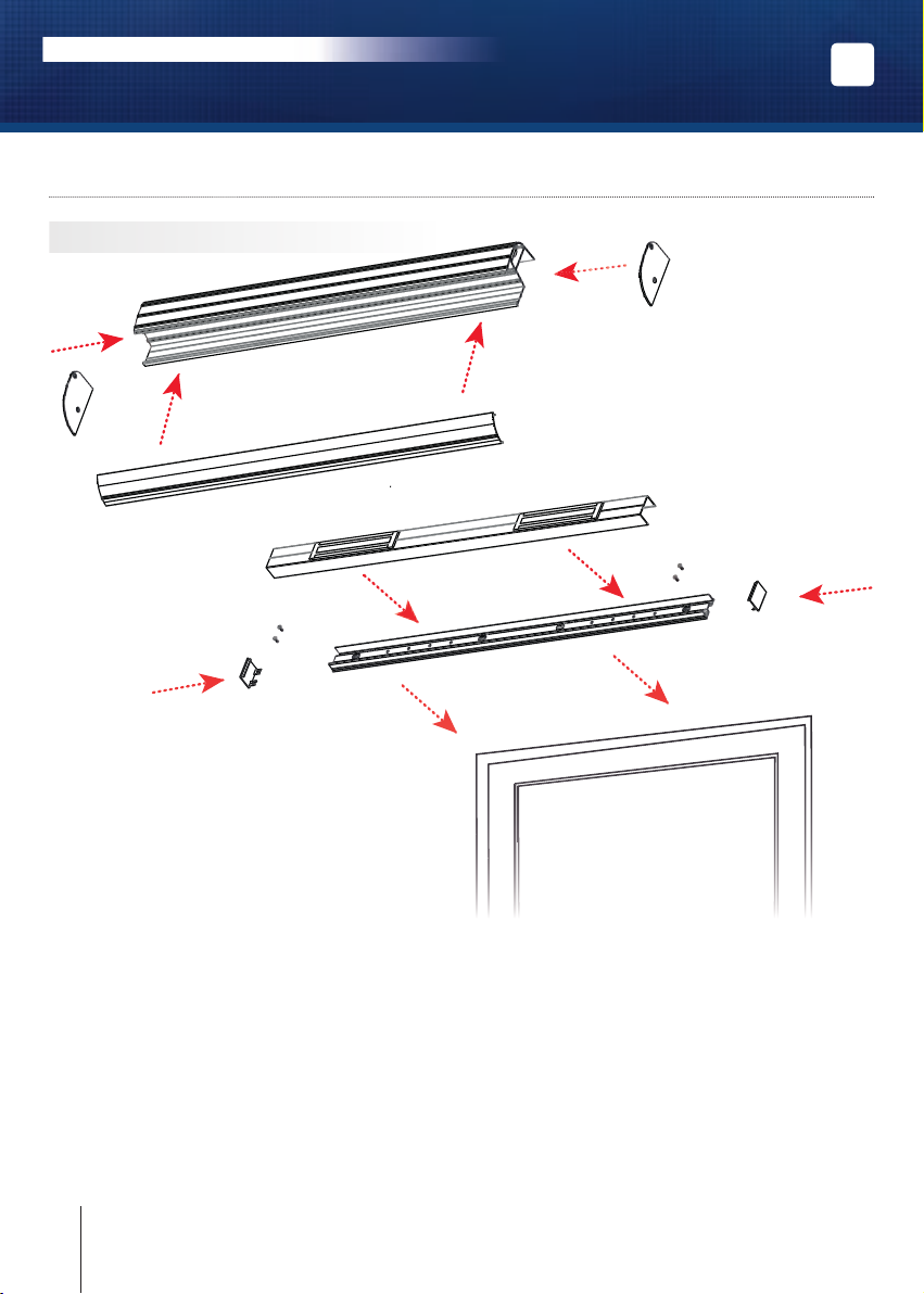
Position the box-section backplate,
complete with pre-fi tted electro-
magnetic locks, on to the door
frame (or fi xed door leaf if
installing onto double doors) -
ensure the positioning will allow
for the architectural handle to
close securely over the section.
Once you are satisfi ed with the
position, mark the vertical and
horizontal holes, then drill as
required. Take note of the cable
entry holes, and feed the cables
through. Fix the section into place,
then wire the electromagnetic
locks in accordance with the
wiring schematic in Section 5. Fit
the box section cover into place,
fi t the end caps and secure with
the screws provided. To fi nalise
the assembly, tighten all fi xings,
and protect the handle fi xing
section by fi tting the cover and
end caps.
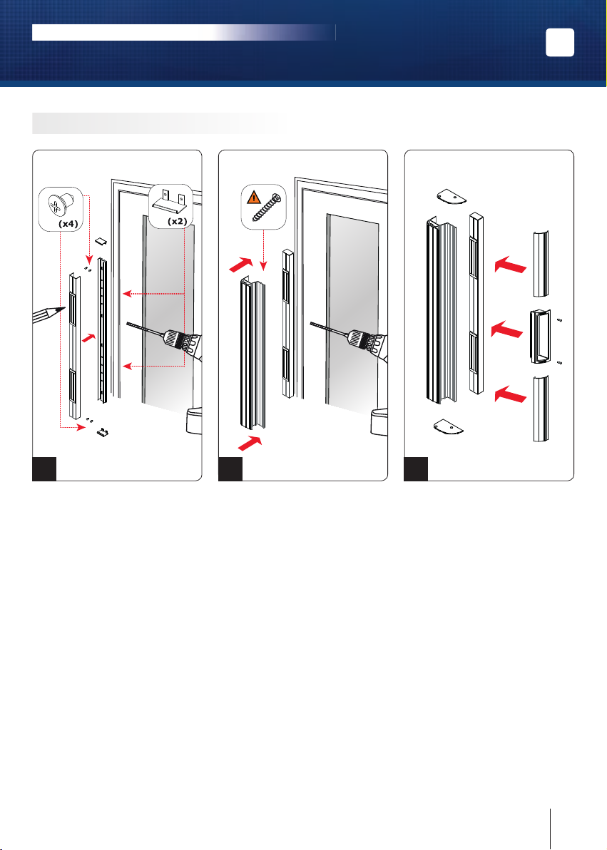
1
Cut the top cover unit into 2
pieces. Double check the length of
each section of top cover before
fi nal cutting. Take into account
the plastic handle (215MM).
Ensure the plastic handle is at
optimum position for users, then
make the fi nal cuts to the covers.
Insert the end caps and secure.
Insert the plastic handle and clip
it into position. Secure the handle
with the 2 screws.
3
With the door closed, position the
architectural handle onto the edge
of the opening leaf of the door,
ensuring the handle covers the
box-section. Mark the vertical and
horizontal holes, drill as required,
then temporarily fi x the handle
leaving a small gap around the
box section – check the alignment
of the magnets in the box section
with the armatures in the handle.
Adjust if necessary, then once
satisfi ed, secure the handle by
completing the fi xings.
2
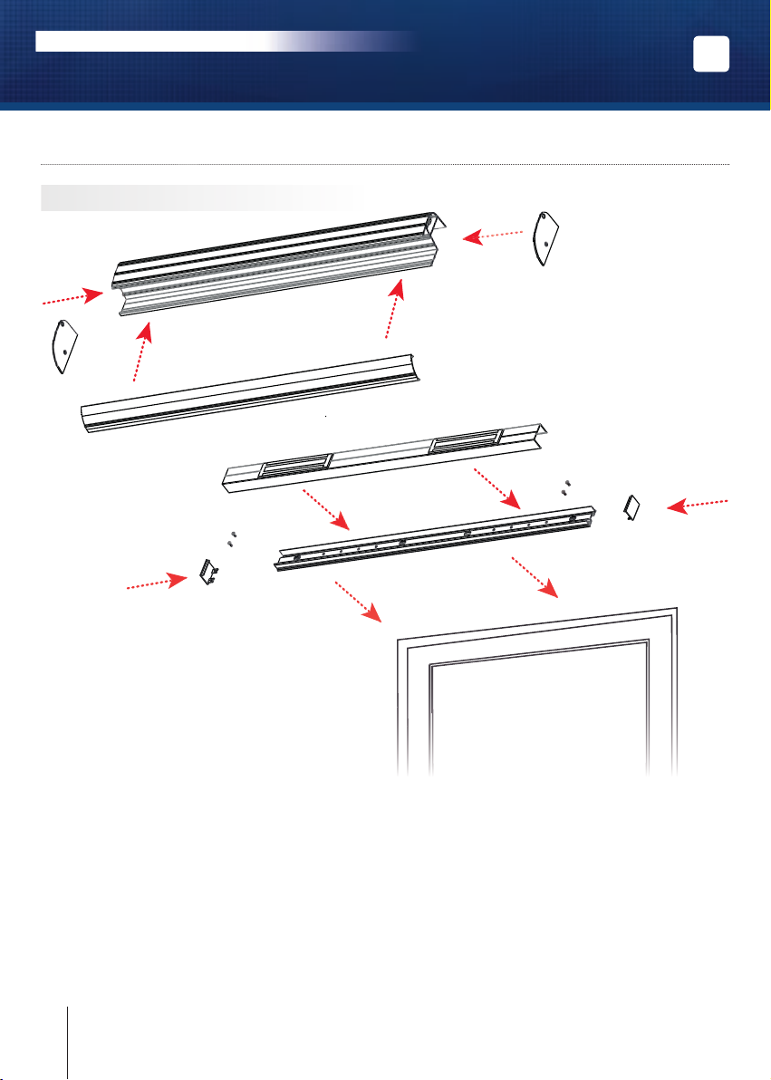
BO600RP