manuals.online logo
Brands
  1. Home
  2. •
  3. Brands
  4. •
  5. Cecilware
  6. •
  7. Dispenser
  8. •
  9. Cecilware HWD2 User manual

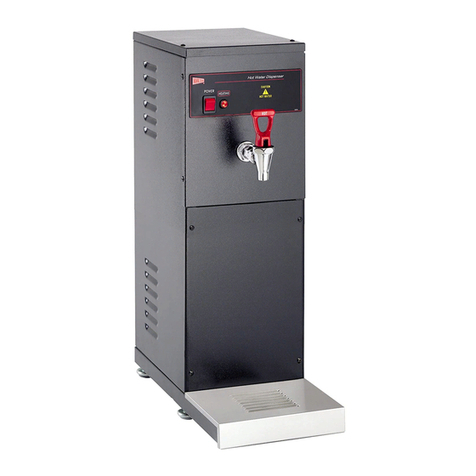
Cecilware HWD2 User manual

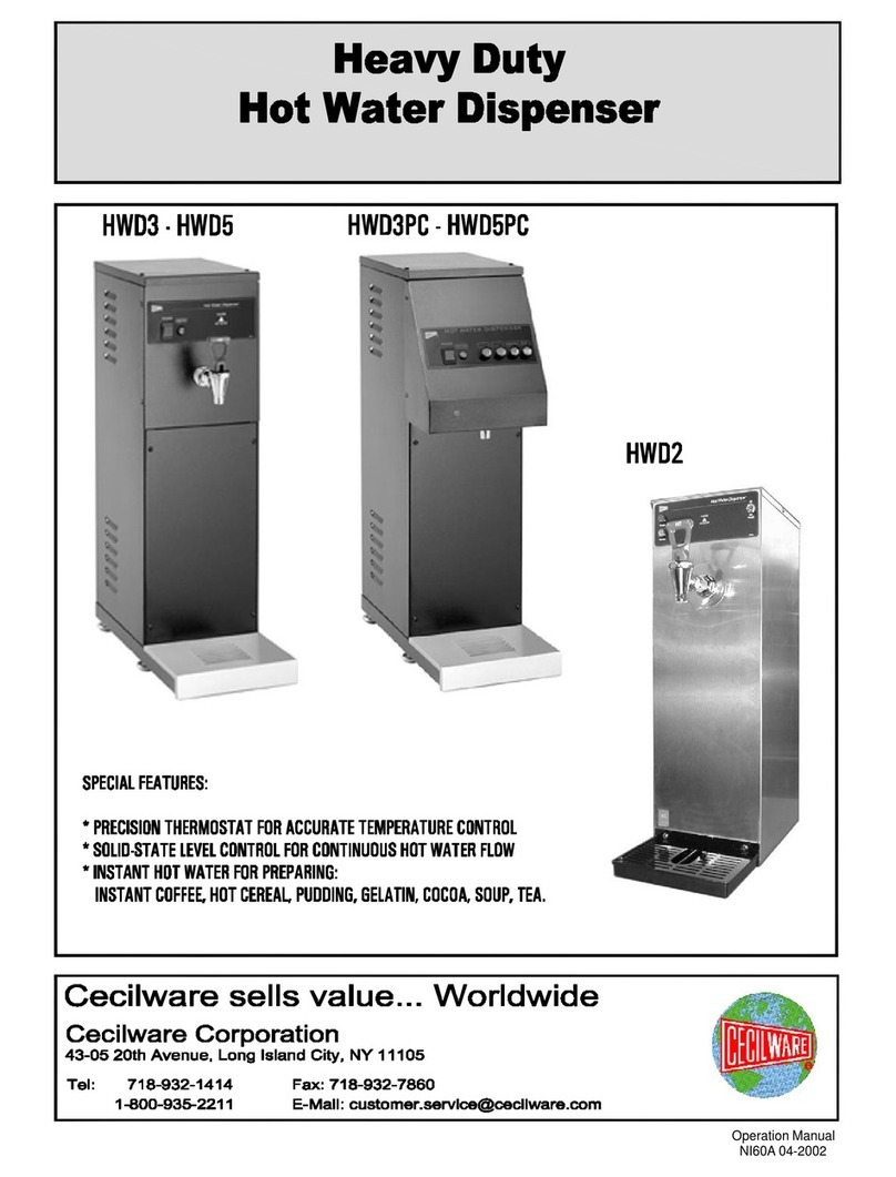
HOT WATER DISPENSER
SPECIFICATIONS
Electrical:
HWD—11750 Watts @ 120VAC, 50/60 HZ
Supplied with a 15A—120V grd. Plug.
HWD—22750 Watts @ 240V, 1 PH, 50/60 HZ
Water Connections:
1/4 O.D Copper Tube for Installations
Less than 15 ft.
3/8 O.D. Copper Tube for Distances
exceeding 15 ft.
Min. Water Pressure: 20 Ibs.
CECILWARE CORPORATION
GENERAL OFFICE & FACTORY
43-05 20th Ave., Long Island City, NY 11105
(718) 932-1414 142034/99
HWD
—
1
120V
HWD—2240V
INSTANT HOT WATER
For Preparing:
Tea
Instant Coffee
Soups
Hot Cereals
Cocoa
Pudding
Gelatins
INSTALLATION:
The unit is shipped with the thermostat in the "OFF" position. CAUTION, do not turn thermostat on before unit is primed with
water.
1. Remove two screws from top cover and remove cover.
2. Flush inlet water line thoroughly before connecting.
If pipe sealant is necessary, Teflon tape is recommended.
3. Connect ¼” O.D. tubing to ¼” flare fitting located at rear of unit. A shutoff valve in the water supply is advisable.
4. Turn on water and check line and fittings for leaks.
5. Examine the electrical data label attached to the machine and plug the power cord into the appropriate power supply.
6. Depress the power switch of the machine to the "ON" position and the water will automatically enter the tank. It will take
approximately 2 1/2 minutes to fill the tank.
7. Turn the thermostat knob to its maximum clockwise position, replace cover and wait approximately 14-25 minutes
for the water to heat.
Note:These instructions are for initial priming only and need not be repeated for normal operation.
PRODUCTION CAPACITY
HWD—1HWD—2
*Initial Heat-Up Time
Burst Capacity
Recovery
Gallons per HR.
*Inlet Water Temp. at68° F
Final Temp.
200°
F
25 minutes
189oz.
19 minutes
4.6
14 minutes
189oz.
10 minutes
8.8
THERMOSTAT ADJUSTMENTS:
Remove the two screws (43) from the top cover and remove cover (Fig. 7). The thermostat will be visible (Fig. 8). First try to adjust
temperature by rotating thermostat knob clockwise to raise temperature, counter-clockwise to lower temperature. If further
adjustment is needed, remove knob exposing shaft with adjustment screw in center of shaft. Turn the adjustment screw counter-
clockwise to raise temperature and clockwise to lower temperature. Unit should be set at 205F or just below boiling. To prevent the
adjustment screw from turning after the adjustment is completed, apply nail polish or Glyptol to the screw.
TROUBLESHOOTING GUIDE:
Warning: Unplug the dispenser power cord before repairing or replacing any internal components of unit.
Trouble Probable CauseRemedy
No water from
1. Line cord not plugged in
1. Plug in line cord
faucet
2.
Power switch "OFF"
2.
Turn power switch "ON"
3. Power switch inoperative
3. Replace switch
4.
Circuit breaker tripped
4.
Reset breaker
5. Water supply off
5. Turn on water supply
6.
Solenoid valve inoperative
6.
Replace solenoid
7. Reed switch inoperative
7. Replace Reed switch
8. Relay inoperative 8. Replace relay
Water continues 1. Leaking solenoid valve 1. Repair or replace valve
to flow from
2. Reed switch inoperative
2. Replace Reed switch
overflow
3.
Ball float sticking or
3.
Clean or replace ball float
contains water
Cold water 1. Thermostat in "OFF" position 1. Turn thermostat "ON"
2. Thermostat inoperative
2. Replace thermostat
3.
Hi
-
l
imit inoperative
3.
Replace hi
-
limit
4.
Heating element opened
4.
Replace element
5.
Loose electrical connections
5.
Tighten all loose
connections
Water boils 1. Thermostat out of adjustment 1. Follow thermostat
continuously
adjustment procedure
in manual and adjust
thermostat
2. Thermostat inoperative 2. Replace thermostat
PARTS LIST
Dwg.
No. Description Part
No. Qty.
Per Unit
Dwg.
No. Description Part
No. Qty.
Per
Unit
1Overflow -copper 77206 123 ½”—20 Hex Nut 03051 2
2Valve -Tank Tube 77207 124 Copper Washer 07059 2
3Faucet 80234 125 Hex Nut 6-32 03006 2
4Water Valve 120V 80235 126 High Limit Switch 59023 1
Water Valve 240V 80236 127 Hex Nut 8-32 03003 5
5Drip Pan Studs 92007 228 Back Panel 40805 1
6Tank Seal 20042 129 Line Cord 120V-15A C032C 1
7Top Cover 40804 1
8Thermostat L266C 130 Strain Relief 57032 1
9#8x1/2” Screw 06211 431 Drip Pan 75014 1
10 Tank Clamps 73290 432 Grill 75015 1
11 Tinnerman Nut 03012 433 Overflow (Silicone) 77205 1
12 Tank Insulation 38310 134 Hose Clamp 34031 2
13 Inlet Fitting Assy. 95101 135 #8 x ½ Type A Screw 06110 4
14 Henry Strainer E002C 136 Rubber Bumpers18009 4
15 Relay (Wired) 120V L018C 137 Faucet Shank 77203 1
Relay (Wired) 240V L159C 1Washer 07221 1
16 Power Switch L155C 138 Cabinet Assy. 97153 1
17 Hot Water Label N096C 139 Lock Washer 07005
18 Tank Top Assy. 97156 140 Tank Sub –Assy. 97154 1
19 Float Ball 24004 141 Tinnerman Nut 03016 2
20 Retainer Ring 38568 142 8-32x1/2 R H Screw 06111 5
21 Float Switch Assy. L019C 143 6-32x1/4 R H Screw 06091 4
22 Heating Element 120V 87039 144 Thermostat Knob M193C 1
Heating Element 240V 87040 145 Tank Nut ¼-20 03063 2

Other manuals for HWD2

3

This manual suits for next models

1

Other Cecilware Dispenser manuals

Cecilware DELICE CHOCO-1 User manual

Cecilware

Cecilware DELICE CHOCO-1 User manual

Cecilware TB Series User manual

Cecilware

Cecilware TB Series User manual

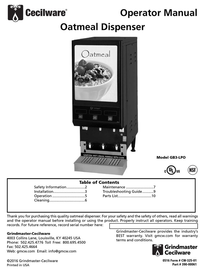
Cecilware GB3-LPO User manual

Cecilware

Cecilware GB3-LPO User manual

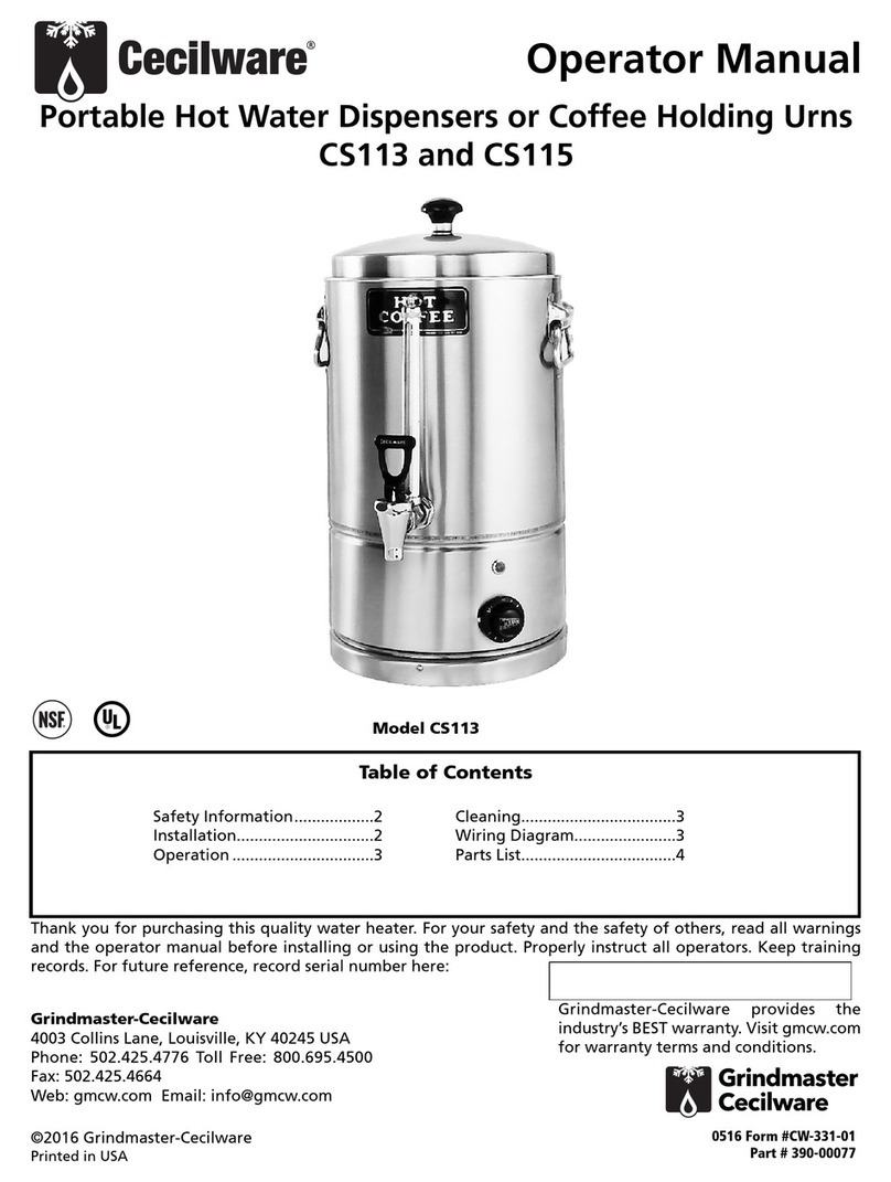
Cecilware CS113 User manual

Cecilware

Cecilware CS113 User manual

Cecilware HWD2 User manual

Cecilware

Cecilware HWD2 User manual

Cecilware TT1 User manual

Cecilware

Cecilware TT1 User manual

Cecilware Radiance 5 Operating manual

Cecilware

Cecilware Radiance 5 Operating manual

Cecilware Giant 2-UL User manual

Cecilware

Cecilware Giant 2-UL User manual

Cecilware HWD2 User manual

Cecilware

Cecilware HWD2 User manual

Cecilware GB1P User manual

Cecilware

Cecilware GB1P User manual

Cecilware GB1M-IT User manual

Cecilware

Cecilware GB1M-IT User manual

Cecilware NHV-2-UL User manual

Cecilware

Cecilware NHV-2-UL User manual

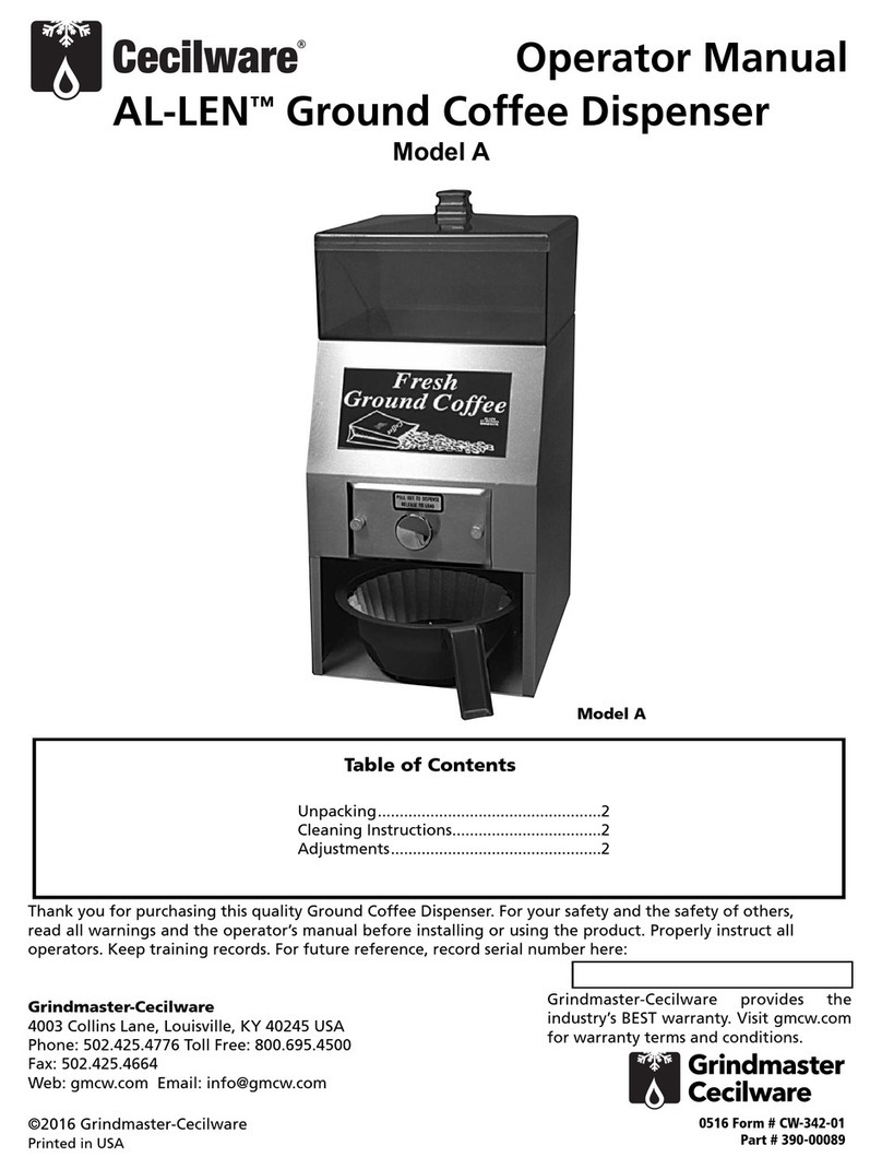
Cecilware AL-LEN A User manual

Cecilware

Cecilware AL-LEN A User manual

Popular Dispenser manuals by other brands

Guardian SD410 Use & care instructions

Guardian

Guardian SD410 Use & care instructions

U-Line SLIMFOLD H-4701 manual

U-Line

U-Line SLIMFOLD H-4701 manual

Narvon SLUSHY 378SM2 Service manual

Narvon

Narvon SLUSHY 378SM2 Service manual

DEMA 652GAP installation instructions

DEMA

DEMA 652GAP installation instructions

Sprintis E2025 Instruction

Sprintis

Sprintis E2025 Instruction

Event Furniture 240VOLT Operating & safety guide

Event Furniture

Event Furniture 240VOLT Operating & safety guide

Pentair INTELLIpH Installation and user guide

Pentair

Pentair INTELLIpH Installation and user guide

Casselin CDS1 operating instructions

Casselin

Casselin CDS1 operating instructions

Bartscher 200065 instruction manual

Bartscher

Bartscher 200065 instruction manual

KWC ONO nstallation and Service Manual

KWC

KWC ONO nstallation and Service Manual

Hupfer UST/57-28 operating instructions

Hupfer

Hupfer UST/57-28 operating instructions

Schroeder America ARIZONA TEA DISPENSER 925 Installation instruction, parts list and configuration guide

Schroeder America

Schroeder America ARIZONA TEA DISPENSER 925 Installation instruction, parts list and configuration guide

Wayne Reliance G6101D Installation & operation

Wayne

Wayne Reliance G6101D Installation & operation

U-Line H-2307 Mounting instructions

U-Line

U-Line H-2307 Mounting instructions

Graco PCF Instructions and parts

Graco

Graco PCF Instructions and parts

Franke RODX618E Installation and operating instructions

Franke

Franke RODX618E Installation and operating instructions

Vestergaard LifeStraw manual

Vestergaard

Vestergaard LifeStraw manual

COLORATO CLSD-100GP instruction manual

COLORATO

COLORATO CLSD-100GP instruction manual

manuals.online logo
manuals.online logoBrands
  • About & Mission
  • Contact us
  • Privacy Policy
  • Terms and Conditions

Copyright 2025 Manuals.Online. All Rights Reserved.