Cedes GridScan/Pro User manual

EN 12453
E device
GridScan/Pro
Installation and Operation Manual
114 996 | 190521 | V 1.0
English Pages 1 – 13 Original version
Deutsch Seiten 14 – 25
Français Pages 26 – 37
Italiano Pagine 38 – 49
Español Páginas 50 – 61
日本語 ページ 62 – 73
CEDES AG is certified according to ISO 9001: 2015
RoHS
EN 13849-1

GridScan/Pro English
2 © CEDES | V 1.0
1. About this manual
This installation and operation manual in English, with
metric and inches measurements is the original version.
The version number is printed at the bottom of each page.
To make sure you have the latest version, visit
www.cedes.com where this manual and related documents
can be downloaded.
1.1 Measurements
Measurements are, if not stated otherwise, given in mm
(non-bracketed numbers) and inches (numbers in brackets).
1.2 Related documents
GridScan/Pro datasheet
001 233 en
1.3 CEDES headquarters
CEDES AG
Science Park
CH-7302 Landquart
Switzerland
1.4 Certification Body
TÜV NORD CERT GmbH
Langemarckstr. 20
DE-45141 Essen
Germany
CEDES AG reserves the right to modify or change technical data without prior notice.
Contents
1. About this manual 2
1.1 Measurements 2
1.2 Related documents 2
1.3 CEDES headquarters 2
1.4 Certification Body 2
2. Safety information 3
2.1 Non-intended use 3
3. Symbols, safety messages 3
3.1 Safety messages categories 3
4. Introduction 4
4.1 Features of the GridScan/Pro 4
4.2 Types - GridScan/Pro 4
4.3 Type description 4
4.4 Intended use 4
5. Overview 5
5.1 Delivery package 5
5.2 General instructions and precautions 5
5.3 Alignment 6
6. Application overview 6
6.1 Door blanking 7
7. Installation 7
8. Electrical connection 8
8.1 Outputs 8
8.2 Test input 9
9. Timing diagram 10
10. Start-up 10
11. LED status description 10
12. Troubleshooting 11
13. Maintenance 11
14. Disposal 11
15. Technical data 12
16. Dimensions 13

GridScan/Pro English
© CEDES | V 1.0 3
2. Safety information
The GridScan/Pro was developed and manufactured using
state-of-the-art systems and technologies. However, injury
and damage to the sensor can still occur.
To ensure safe conditions:
Read all enclosed instructions and information.
Follow the instructions given in this manual carefully.
Observe all warnings included in the documentation
and attached to the sensor.
Do not use the sensor if it is damaged in any way.
Keep the instruction manual on site.
The GridScan/Pro should only be installed by authorized
and fully trained personnel! The installer or system
integrator is fully responsible for the safe integration of the
sensor. It is the sole responsibility of the planner and/or
installer and/or buyer to ensure that this product is used
according to all applicable standards, laws and regulations
in order to ensure safe operation of the whole application.
Any alterations to the device by the buyer, installer or user
may result in unsafe operating conditions. CEDES is not
responsible for any liability or warranty claim that results
from such manipulation.
Failure to follow instructions given in this manual and/or
other documents related to the GridScan/Pro may cause
customer complaints, serious call backs, damage, injury or
death.
2.1 Non-intended use
The GridScan/Pro must not be used for:
• Protection of dangerous machine
• Equipment in explosive atmospheres
• Equipment in radioactive environments
Use only specific and approved safety devices for such
applications, otherwise serious injury or death or damage
to property may occur!
3. Symbols, safety messages
3.1 Safety messages categories
Warning of serious health risks
WARNING
Serious health risks
Highlights critical information for the safe use
of the sensor. Disregarding these warnings
can result in serious injury or death.
Follow the measures highlighted by the
triangle-shaped arrows
Consult the safety information in Chapter
2 of this manual
Caution of possible health risk
CAUTION
Possible health risks
Highlights critical information for the safe use
of the sensor. Disregarding these warnings
can result in injury.
Follow the measures highlighted by the
triangle-shaped arrows
Consult the safety information in Chapter
2 of this manual
Notice of damage risk
NOTICE
Risk of damage
Disregarding these notices can lead to
damage to the sensor, the door controller
and/or other devices.
Follow the measures highlighted by the
triangle-shaped arrows
Symbol Meaning
Single instruction or measures in no
particular order
1.
2.
3.
Sequenced instructions
• List, in no order of importance
àReference to a chapter, illustration or
table within this document
Important Important information for the correct use
of the sensor
IMPORTANT
READ BEFORE INSTALLATION!

GridScan/Pro English
4 © CEDES | V 1.0
4. Introduction
The GridScan/Pro is a very reliable SIL 2 certified safety
light curtain. It was developed and designed to safeguard
all types of industrial doors such as sectional or high-speed
doors. The system is ideal for door openings up to 10 m
wide and can handle door closure speed of 1.6 m/s. The
opening speed is up to 3 m/s. The emitter and receiver can
be installed directly into the guide rail (blanking version)
or to the front or the back of the door (static version).
Therefore, a blanking version as well as a static version
(without door blanking) are available.
The GridScan/Pro has a selectable output of Frequency
Safety Signal (FSS) or Push-Pull, so one system can handle
all relevant outputs. Selecting the FSS output allows
operation according to EN ISO 13849-1:2015 Cat. 2
without periodic testing of the light curtain. This output is
included in the TÜV certification of the GridScan/Pro.
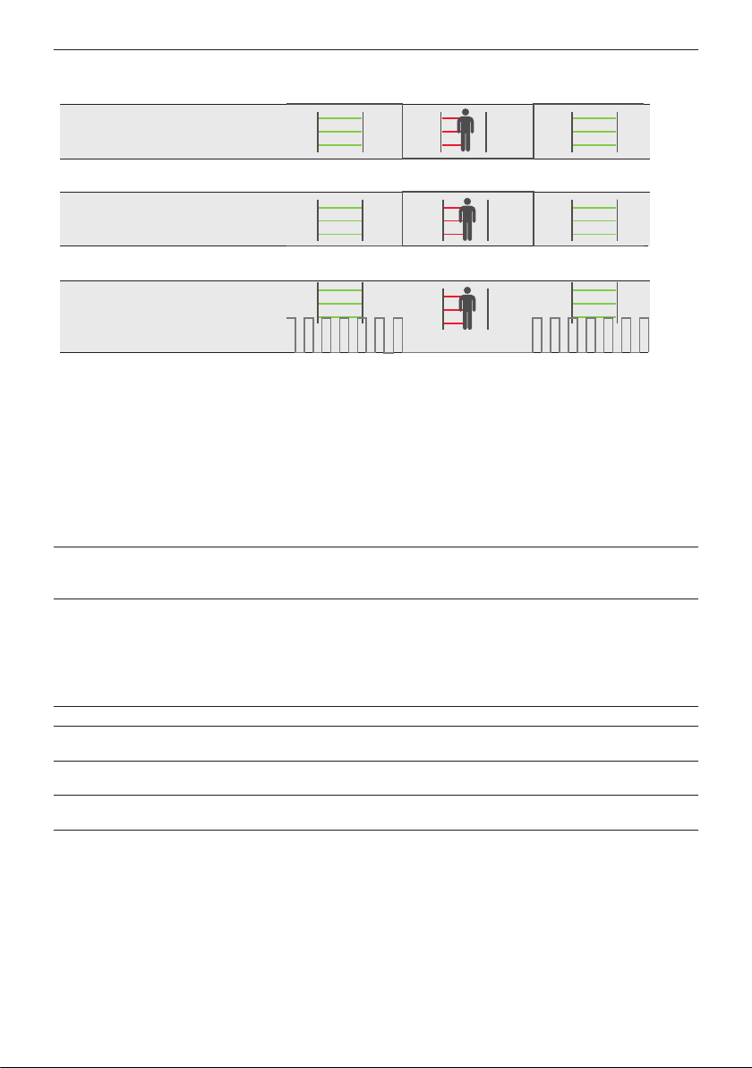
Figure 1: Typical GridScan/Pro application environments
4.1 Features of the GridScan/Pro
• TÜV – EC Type examination certified
• SIL 2 certified
• Direct integration into the door edge due to door
blanking
• Combined output with PNP/NPN (push-pull) and FSS
• Easiest alignment
• 2nd output for additional information
• Ideal for modernization projects due to FSS control
unit
• Door closing speed up to 1.6 m/s
• Fulfils SIL 2 without testing if FSS output selected
• Version with communication interface available
• Cross section only 12 mm × 14.5 mm
4.2 Types - GridScan/Pro
• Standard
The standard type features door blanking and resolution,
according to EN 12978:2009. This means there are
different resolutions between elements along the length of
the edge.
Important: The standard type is certified according to EN
ISO 13849-1:2015 and EN 12978:2009 if the door is
monitored over its full height up to 2.5 m (8.2 ft).
• ST type
The ST type has no door blanking feature. It can be used as
a Cat. 2 safety light curtain for different applications.
Important: The ST type is certified according to
EN ISO 13849-1:2015 and EN 12978:2009 if the door is
monitored over its full height up to 2.5 m (8.2 ft).
4.3 Type description
Figure 2: Type description
Example:
• GRS/Pro SY-2500-22
GridScan/Pro system, 2500 mm safety length, 22 elements
4.4 Intended use
The GridScan/Pro is designed and approved for the
mounting and use in- and outside guiding rail of industrial
doors application to protect persons according to
EN 12978:2009 and EN 12453:2017.
The GridScan/Pro can be used as a safety device according
EN 12453:2017 as E-device and fulfills the safety levels
up to SIL 2 according to EN 61508:2010 and the category
2 (cat. 2) / performance level d (PL d) according to
EN ISO 13849-1:2015.
GRS/Pro – aa – bbbb – cc, dd, ee, ff
aa : SY System
Tx Emitter
Rx Receiver
dd : - Standard type with blanking
ST Static type
bbbb : Safety length in mm
cc : Number of elements
ee : Information of output 1 (factory settings)
ff : Information of output 2 (factory settings)

GridScan/Pro English
© CEDES | V 1.0 5
5. Overview
The emitter and receiver edges create a grid of infrared beams offering up to 2.5 m (8.2 ft) in protection height. When the
infrared beams are interrupted, the output sends a signal to the connected door control unit. As soon as the detection area
is clear again, the output switches to indicate that the area is "clear". The blanking system (standard versions, Chapter
4.2) is designed to mount directly into the guide rails. As the door closes, the GridScan/Pro recognizes the door as such
and does not switch the output.
Figure 3: Sectional doors with door blanking
5.1 Delivery package
The GridScan/Pro package comprises:
• 1 × GridScan/Pro emitter edge (Tx)
• 1 × GridScan/Pro receiver edge (Rx)
• 1 × Synchronization cable 10 m (33 ft)
• 1 × Connection cable 5 m (16.5 ft)
• 1 × Installation guide
5.2 General instructions and precautions
Figure 4: High-speed doors with door blanking
Figure 5: Typical GridScan/Pro delivery package
Never scratch or paint the optical lenses because they form the
light path! Do not drill additional holes into the profile. Unpack
the profiles just before installation in order to avoid damage.
Do not bend or twist the edges!
Oil can damage the cables. Contamination must be avoided at
all times!
Chemical can damage the profile and optical characteristics.
Contact must be avoided at all times!

GridScan/Pro English
6 © CEDES | V 1.0
5.3 Alignment
6. Application overview
Synchronization cable
Connection cable
Emitter edge
Door operator
Receiver edge
Door
controller
Figure 6: GridScan/Pro application (overview)
Figure 7: GridScan/Pro with door
blanking (standard type)
Figure 8: GridScan/Pro with static
mounting (ST type)
Make sure to place the connection plugs for both the emitter and
receiver at the same end.
Although the GridScan/Pro is insensitive to direct sunlight,
avoid all unnecessary exposure if possible, most especially to
the receiver.
Avoid interference from blinking lights or infrared light sources
such as photo cells or other light curtains.
Do not install the GridScan/Pro in places where the emitter and
receiver edges are directly exposed to light sources such as FL
tubes or energy saving lamps.
TxRx RxTx
Tx Rx Tx
R
x
The optical axis of the emitter (Tx) and the receiver edge (Rx) need to
be aligned towards each other to ensure the light curtain functions
reliably.
Reflective surfaces near to or parallel to the safeguarded area can
cause reflections and interfere with the GridScan/Pro's functions.
Keep a reasonable distance between the sensor edges and any
reflective surface.
A self calibration on each optical beam is implemented. At the
power- up the ideal emitting strength will be detected and used. To
reduce interruption caused of dust the system checks the emitting
power and adapt a new higher or lower strength if necessary.
Tx Rx
Reflective surface
Tx
Rx
≤ 5˚≤ 5˚
< 3 m
CAUTION
Damage to the eye
Although the GridScan/Pro does not emit dangerous
amounts of infrared light, long exposure to intense infrared
light sources can result in damage to the eyes.
Never look directly into the active infrared emitter from
a close distance.

GridScan/Pro English
© CEDES | V 1.0 7
6.1 Door blanking
The GridScan/Pro can differentiate between a light beam interruption caused by an object and a light beam interruption
caused by the closing door. The GridScan/Pro does this by analyzing the different interruption patterns.
Closing door interruption pattern:
The light beam interruption of a closing door starts at the topmost beam going downwards. There are two ways to achieve
blanking:
Min. height of
the lower end
of the door
Optical element
GridScan/Pro edge
Figure 9.1 Door blanking through door edge
7. Installation
1. Switch off main power to the door control unit and mark clearly that this system is out
of service before performing any work on the system.
2. Mount the receiver edge on one side of the door.
Important for standard types:
Mount the receiver edge into the guiding rail next to the door control unit
(Figure 7).
In order to fulfill EN 12978:2009 the lower end of the edges have to be at the level of
the door closed position.
Important for ST types:
When the GridScan/Pro is statically mounted (Figure 8) the door must not interrupt
the beams (no door blanking).
Figure 10: Front mounting
When the GridScan/Pro is integrated into the guide rail, the
door moves directly in front of the light curtain. This means
the lowest section of the door needs to be at least 30 mm
in height to ensure that at least one element is completely
covered. It is also essential that the door's leading edge
extends the full distance between the light curtain's emitter
and receiver (Figure 9.1).
If the light curtain is located either in front of or behind the
guide rail, the descending door will not interrupt the active
beams. However, blanking may still be required if any part
of the door (e.g. cable) interrupts the light curtain. A beam
blocker can be used but it must be mounted so that at least
one element is continuously covered during door closure
(Figure 9.2).
Optical element
GridScan/Pro edge
Min. distance always
covered by the
beamblocker
Figure 9.2 Door blanking through beam blocker
WARNING
Electrical and mechanical hazards
Electrical shock and unexpected door
movement can cause serious injury or
death.
Follow all applicable safety measures.
Use only specific and approved tools.
If the GridScan/Pro has to be adjusted, the
main power supply must be switched off
and marked as out of service.
NOTICE
Mechanical damage to the
GridScan/Pro
Do not drill additional holes into the light
curtain.
Do not overtighten the mounting screws.
Mount the edges on a flat surface.

GridScan/Pro English
8 © CEDES | V 1.0
3. Mount the emitter edge across from the receiver edge. If the receiver is mounted in the guiding rail the emitter
should be mounted in the guiding rail opposite the receiver.
Important: Make sure the optical elements are facing each other (Chapter 5.3).
4. Connect the emitter with the receiver edge using the synchronization cable.
5. Plug the connection cable into the blue plug on the receiver edge and connect it to the door controller (Chapter 8).
8. Electrical connection
Figure 11: Connection diagram
Important: Any unconnected (not used) wire must be separated and isolated.
8.1 Outputs
When an object enters the safeguarded area (OBJECT DETECTED) the GridScan/Pro output changes after response time
t2(Chapter 9). When the object leaves the safeguarded area (NO OBJECT) the GridScan/Pro output switches back after
release time t3.
8.1.1 Changing the output logic
Output 1 logic is set using the gray wire. The logic will
be defined by the power-up sequence. After the power-
up the logic will not change until the next power-up
is made. The default logic is LO (light-on) (used in the
timing diagram). The output logic is LO if the gray wire is
connected to GND (0 V). Connecting the gray wire to USP
(10 ... 30 VDC) changes the output logic to DO (dark-on).
If the gray wire is not connected (floated), the output logic
changes to the FSS signal.
5
2
4
3
1
6
Selectable output logic
Test input*
Output 1 (PNP/NPN and FSS)
USP
GND (0 V)
Not used or Output 2 (PNP/NPN)
Door
controller
Tx Rx
M8, 6-pin
brown
black
gray
white
Synchronization
cable
* If FSS output is
selected white wire needs
to be connected to USP
or test signal
blue
green
Tx // Rx
Tx not // Rx
Tx not // Rx
Gray wire Output 1 Logic
Connected to GND (0 V) Push-Pull LO
Connected to USP Push-Pull DO
Not connected (floated) FSS
Table 1: Output 1 logic selection table

GridScan/Pro English
© CEDES | V 1.0 9
Figure 12: Output 1 logic
8.1.2 FSS output (Frequency Safety Signal)
The FSS is a 1 kHz safety output allowing for safeguarding according to EN ISO 13849-1:2015, without using a test signal.
As long as the safeguarded area is free, the FSS output sends a 1 kHz signal. When an object enters the safeguarded
area (OBJECT DETECTED), the FSS output switches to LOW/GND (0 V). When the object leaves the safeguarded area (NO
OBJECT) the frequency starts again (Chapter 9).
8.1.3 Output 1 - factory settings
Output 1 is delivered in the following versions. The settings refer to the "ee" type description (see Chapter 4.3).
Other options are available on request.
8.1.4 Output 2 - factory settings
Output 2 (PNP/NPN) is delivered in the following versions. The settings refer to the "ff" type description (see
Chapter 4.3).
Other options are available on request.
8.2 Test input
To fulfil EN ISO 13849-1:2015 the GridScan/Pro with PNP/NPN output (N type) must be tested by the door controller
before each door closing cycle. The GridScan/Pro is available in a standard version with "Test active LOW".
Important: When the FSS output is used, using the test input is not necessary to achieve safeguarding according to
EN ISO 13849-1:2015. In this case, the white wire has to be connected to the USP.
USP
0 V
USP
Output selector connected to GND (0 V )
Output selector connected to USP
0 V
Output 1 (PNP/NPN LO)
Output 1 (PNP/NPN DO)
3.9 VDC
0 V
Output selector not connected (floated)
Output 1 (FSS)
, ee --Output 1 switches when person/object is detected or 3 seconds after door closure
(reactivates when the 11th element from bottom is uninterrupted again).
ST type Output 1 switches when person/object is detected.
, ff -Standard - no Output 2
, 2Z Output 2 switches when person/object is detected using the single-element detection method (11th element
from the bottom, 490 mm).
, 2Y Output 2 switches when person/object is detected using the single-element detection method. In this case,
the element will be blanked during door blanking (11th element from the bottom, 490 mm).
, 2X Output 2 switches immediately after door closure (reactivates when the lowest element is uninterrupted
again).

GridScan/Pro English
10 © CEDES | V 1.0
9. Timing diagram
Figure 13: General timing diagram
Table 2: General timing table Table 3: General value table
10. Start-up
1. Switch on mains and power-up the door control unit. The LED on the receiver edge blinks during the start-up phase.
2. Check the LED on both edges (power, status).
3. Test if the system is working correctly by letting the door open and close, interrupting the light during the opening
and closing process.
11. LED status description
Receiver edge (Rx) Emitter edge (Tx)
Table 4: LED status description receiver edge
= LED on = LED off = LED blinking
Table 5: LED status description emitter edge
t2
t1t4
t7
t5
t3
t6
HIGH
LOW
HIGH
LOW
Test input (L)
Object
detection
Output (PNP/NPN)
NO OBJECT
OBJECT
TEST
USP
GND
Power supply
HIGH
LOW
FSS output
Time Value [ms]
Power-up time t1max. 1,700
Response time with 22
elements
t2typ. 40
max. 80
Release time t3max. 50
Test response time t4max. 80
Restart time t5max. 200
FSS sequence time t61
Test time t7min. 100
PNP / NPN
Power supply USP 10 ... 30 VDC
Power supply GND 0 V
Test input HIGH > 10 VDC
Test input LOW < 2 VDC
Output HIGH > USP - 2 VDC
Output LOW < 2 VDC
FSS output HIGH 3.4 … 4.2 VDC
FSS Output LOW < 1 VDC
Green LED Red LED Sensor status
Light curtain free
Safeguarded area interrupted
or door closed
Start-up (slow blinking)
Internal malfunction (fast
blinking)
No power or edge is
defective (see Chapter 12)
Green LED Sensor status
Power OK
No power or edge is defective
(see Chapter 12)

GridScan/Pro English
© CEDES | V 1.0 11
12. Troubleshooting
Tx LED
Green
Rx LED
Green
Rx LED
Red Action
LED off LED off LED off `Check electrical connections.
`Check supply voltage of the door controller.
LED off LED off LED red `Check the connection of the synchronization cable.
LED green LED green LED off `Make sure the sensor edges are not mounted close to any
shiny or reflective surface.
`Restart the system.
LED off/on
(flickering green)
LED off LED off/on
(flickering red)
`Check power supply.
`Check connections.
LED green LED off LED off/on
(slow blinking red)
`Make sure the safeguarded area is clear of interruption.
`Check the alignment of the light curtain.
`Clean elements.
LED green LED on/off
(flickering green)
LED off/on
(flickering red)
`Make sure the safeguarded area is clear of interruption.
`Clean the elements.
`Make sure that the cables and edges are located away from
sources of electromagnetic interference.
`Ensure that the emitter and receiver are correctly aligned
and remain so during door closure (e.g. that vibrations do
not cause edges to become misaligned).
`Restart the system.
LED green LED off LED red `Make sure the safeguarded area is clear of interruption.
`Reopen door completely.
`Clean the elements.
`Check the alignment of the light curtain.
`Check that the test input is connected to the test output
signal of the door control unit and that the signal level and
logic (HIGH/LOW) are correct. If the test input is not used,
connect it permanently to USP.
`Measure the USP voltage.
`Restart the system.
LED off LED off LED off/on
(slow blinking red)
`Check the connection of the synchronization cable.
LED green LED off LED off/on (red,
fast blinking, 5 Hz)
Internal error occurred
`Restart the system.
`Replace Rx edge.
Important: Whenever a parameter is changed, the system must be restarted.
If a problem persists, please contact your local CEDES representative. Visit www.cedes.com for contact data.
13. Maintenance
Although the GridScan/Pro does not need regular
maintenance, a periodic functional check is strongly
recommended:
`Make sure the optical elements are clear of dirt and dust.
If necessary, clean the front surface with a soft towel.
`Make sure the edges are securely fastened.
`Check the mounting position, cable routing and
connection of the sensor.
14. Disposal
The GridScan/Pro should only be replaced if a similar
protection device is installed. Disposal should be done
using the most up-to-date recycling technology according
to local regulations and laws. There are no harmful materials
used in the design and manufacture of the sensor. Traces
of such dangerous materials may be found in the electronic
components but not in quantities that are harmful.
NOTICE
Damage to the optical elements
Never use any solvents, cleaners or mechanically
abrasive towels or high-pressure water to clean
the sensor.
Avoid scratching the optical elements while
cleaning.

GridScan/Pro English
12 © CEDES | V 1.0
15. Technical data
Optical
Operating range 1...10 m (3 ... 33 ft)
Number of elements 20, 22, 36, 42
Max. protection height 2,500 mm (98.5 in)
Max. ambient light 100,000 Lux
Mechanical
Cross section 12 mm × 14.5 mm
(0.47 in × 0.57 in)
Housing material Natural anodized
aluminum
Enclosure rating IP68 (Cable: IP67)
Temperature range −40 °C ... +60 °C
(−40 °F ... +140 °F)
Electrical
Supply voltage USP 10 ... 30 VDC
Current consumption with 50 mA
22 elements at 24 VDC
Output PNP/NPN (push-pull)
and FSS
Output load 100 mA, 100 nF
Typ. response time with 40 ms
22 elements
Max. response time with 80 ms
22 elements
HW Watch dog 200 ms
Max. door closing speed 1.6 m/s
Max. door opening speed > 3 m/s
Status LED Rx:
- Object detected red
- No object detected green
Power LED Tx:
Power ok green
Connection cable and electrical connection
Synchronization cable
Length 10 m (33 ft)
Connection Screwable M8, 4 pin
Diameter Ø 3.5 mm (Ø 0.14 in)
Material PVC, black
Plug color Black
Wires AWG26
• brown USP
• blue GND (0 V)
• black Communication
• white Not used
Connection cable
Length 5 m (16.5 ft)
Connection Screwable M8, 4 pin
Diameter Ø 4.2 mm (Ø 0.17 in)
Material PVC, black
Plug color Blue
Wires AWG26
• brown USP
• blue GND (0 V)
• black Output 1 (PNP/NPN and
FSS)
• white Test input
• gray Selectable output logic
• green Not used or Output 2
(PNP/NPN)
General
EMC emmision EN 61000-6-3:2007
EN 12015:2014
EMC immunity EN 61000-6-2:2005
EN 12016:2013
Vibration IEC 60068-2-6:2007
Shock IEC 60068-2-27:2008
RoHS 2011/65/EU
Certificates CE, TÜV
Safety categories EN ISO 13849-1:2015,
Cat. 2, PL D
EN 61508:2010, SIL 2
EN 12978:2009
EN 12453:2017 E device
Applicable standards UL 325:2012

GridScan/Pro English
© CEDES | V 1.0 13
16. Dimensions
All dimensions in mm (for 22 elements)
US measurements
All dimensions in inches (for 22 elements)
Receiver edge
Uppermost beam
Mounting hole
LED
Emitter edge
Lowest beam
Mounting hole
Mounting hole
40
330
1187
2130
2350
2420
Receiver edge
Uppermost beam
Mounting hole
LED
Emitter edge
Lowest beam
Mounting hole
Mounting hole
40
330
1187
2130
2350
2420
12
14.5
0.47
0.57

GridScan/Pro Deutsch
14 © CEDES | V 1.0
1. Über diese Anleitung
Diese Anleitung mit metrischen Abmessungen ist eine
Übersetzung der englischen Originalversion.
Die Versionsnummer ist am unteren Rand jeder Seite
abgedruckt.
Die aktuelle Version dieser Anleitung und verwandte
Dokumente können auf www.cedes.com heruntergeladen
werden.
1.1 Massangaben
Alle Längen sind, wenn nicht anders angegeben, in
Millimeter (mm) vermasst.
1.2 Verwandte Dokumente
GridScan/Pro Datenblatt
001 233 de
1.3 CEDES Hauptsitz
CEDES AG
Science Park
CH-7302 Landquart
Schweiz
1.4 Zertifizierungsstelle
TÜV NORD CERT GmbH
Langemarckstr. 20
DE-45141 Essen
Deutschland
Inhalt
1. Über diese Anleitung 14
1.1 Massangaben 14
1.2 Verwandte Dokumente 14
1.3 CEDES Hauptsitz 14
1.4 Zertifizierungsstelle 14
2. Sicherheitshinweise 15
2.1 Nicht bestimmungsgemässe Verwendung 15
3. Symbole und Sicherheitshinweise 15
3.1 Warnhinweiskategorien 15
4. Einleitung 16
4.1 Merkmale von GridScan/Pro 16
4.2 Typen - GridScan/Pro 16
4.3 Typenbeschreibung 16
4.4 Bestimmungsgemässe Verwendung 16
5. Übersicht 17
5.1 Lieferumfang 17
5.2 Allgemeine Sicherheitshinweise 17
5.3 Ausrichtung 18
6. Anwendungsübersicht 18
6.1 Torausblendung 19
7. Montage 19
8. Elektrische Anschlüsse 20
8.1 Ausgänge 20
8.2 Testeingang 21
9. Zeitdiagramm 22
10. Inbetriebnahme 22
11. LEDAnzeigen 22
12. Fehlerbehebung 23
13. Wartung 23
14. Entsorgung 23
15. Technische Daten 24
16. Abmessungen 25

GridScan/Pro Deutsch
© CEDES | 1.0 15
2. Sicherheitshinweise
GridScan/Pro wurde mit den neuesten Systemen und
Technologien entwickelt und hergestellt. Trotzdem können
Schäden und Verletzungen auftreten.
Für sichere Arbeits- und Betriebsbedingungen:
Alle relevanten Dokumente lesen.
Alle Anweisungen in dieser Anleitung befolgen.
Alle Warnungen in dieser Anleitung und auf dem Gerät
beachten.
Beschädigte Sensoren nicht mehr benutzen.
Bedienungsanleitung beim Sensor aufbewahren.
GridScan/Pro darf nur von ausgebildetem und
autorisiertem Fachpersonal installiert werden! Der
Monteur ist dazu verpflichtet, alle entsprechenden vor Ort
geltenden Gesetze und Normen einzuhalten. Der Monteur
oder Systemintegrator trägt die volle Verantwortung für
die sichere Montage des Sensors. Der Planer und/oder
Monteur und/oder Käufer tragen die volle Verantwortung
für die Einhaltung aller relevanten Gesetze und Normen,
die dieses Produkt betreffen, um einen sicheren Betrieb
der gesamten Anwendung sicherzustellen.
Sämtliche Änderungen an der Vorrichtung durch
Käufer, Monteur oder Benutzer können zu unsicheren
Betriebsbedingungen führen. CEDES übernimmt für
Schäden, die durch solche Manipulationen entstanden
sind, keine Haftung oder Garantieansprüche.
Nichtbeachten kann Klagen durch Kunden hervorrufen,
Rückrufmassnahmen, Sachschäden, Verletzungen oder
Tod zur Folge haben.
2.1 Nicht bestimmungsgemässe Verwendung
GridScan/Pro darf nicht eingesetzt werden:
• Absicherung von gefährlichen Maschinen
• Anlagen in explosiven Atmosphären
• Anlagen in radioaktiven Atmosphären
Für Anwendungen dieser Art dürfen nur spezielle,
dafür zugelassene Sicherheitsvorrichtungen eingesetzt
werden. Andernfalls kann dies zu schweren Verletzungen,
Todesfällen oder Sachschäden führen!
3. Symbole und Sicherheitshinweise
3.1 Warnhinweiskategorien
Warnung vor schwerwiegenden Gesundheitsgefahren
WARNUNG
Schwerwiegende
Gesundheitsgefahren
Enthält wichtige Informationen zur sicheren
Nutzung des Sensors. Nichtbeachten dieser
Warnungen kann zu schweren Verletzungen
oder zum Tod führen.
Handlungsaufforderungen nach
dreieckigen Pfeilen befolgen
Die Sicherheitshinweise in Kapitel 2
dieser Anleitung beachten
Hinweis auf mögliche Gesundheitsgefahren
VORSICHT
Mögliche Gesundheitsgefahren
Weist auf wesentliche Informationen
zum sicheren Gebrauch des Sensors hin.
Nichtbeachten dieser Hinweise kann zu
Verletzungen führen.
Handlungsaufforderungen nach
dreieckigen Pfeilen befolgen
Die Sicherheitshinweise in Kapitel 2
dieser Anleitung beachten
Hinweis auf Sachschäden
HINWEIS
Gefahr von Sachschäden
Nichtbeachten dieser Hinweise kann zu
Schäden am Sensor, der Türsteuerung und/
oder anderen Einrichtungen führen.
Handlungsaufforderungen nach
dreieckigen Pfeilen befolgen
Symbol Bedeutung
Einzelne Handlungsaufforderung ohne
bestimmter Reihenfolge
1.
2.
3.
Handlungsaufforderung in einer
bestimmten Reihenfolge
• Aufzählungspunkt, Reihenfolge ist
unerheblich
àVerweis auf ein Kapitel, eine Abbildung
oder Tabelle in diesem Dokument
Wichtig Wichtige Informationen zur richtigen
Nutzung des Sensors
WICHTIG
VOR DER MONTAGE LESEN!

GridScan/Pro Deutsch
16 © CEDES | V 1.0
4. Einleitung
GridScan/Pro ist ein äusserst zuverlässiger, SIL-2-
zertifizierter Sicherheitslichtvorhang. Entwickelt und
konzipiert wurde er zur Absicherung von Industrietoren aller
Art, wie Sektionaltore oder Schnelllauftore. Das System
eignet sich ideal für bis zu 10 m breite Toröffnungen und
kann Schliessgeschwindigkeiten von 1.6 m/s handhaben.
Die Öffnungsgeschwindigkeit beträgt bis zu 3 m/s. Sender
und Empfänger können direkt in die Führungsschiene
(Version mit Torausblendung) oder vorne oder hinten am
Tor (statische Version) eingebaut werden. Somit steht
eine Version mit Torausblendung wie auch eine statische
Version (ohne Torausblendung) zur Verfügung.
Der Ausgang des GridScan/Pro kann auf Frequency Safety
Signal (FSS) oder Push-Pull eingestellt werden, so dass mit
einem einzigen System alle relevanten Ausgänge abgedeckt
sind. FSS erlaubt den Betrieb nach EN ISO 13849-1:2015
Kat. 2, ohne dass der Lichtvorhang regelmässig getestet
werden muss. Dieser Ausgang ist in der TÜV-Zertifizierung
des GridScan/Pro enthalten.
Abb 1: Typische GridScan/Pro Anwendungsumgebungen
4.1 Merkmale von GridScan/Pro
• TÜV-Baumustergeprüft
• SIL 2 zertifizierter Lichtvorhang
• Direkter Einbau in die Führungsschiene des Tors
möglich (Torausblendung)
• Kombinierter Ausgang mit PNP/NPN (push-pull) und
FSS
• Einfachste Ausrichtung
• Zweiter Ausgang für zusätzliche Informationen
• Ideal für Modernisierungsprojekte dank FSS-
Sicherheitsrelais
• Für Torgeschwindigkeiten bis 1.6 m/s
• Erfüllt SIL 2 ohne Test bei Auswahl des FSS-Ausgangs
• Version mit Kommunikationschnittstelle verfügbar
• Leistenquerschnitt nur 12 mm × 14.5 mm
4.2 Typen - GridScan/Pro
• Standard
Der Standardtyp verfügt über Torausblendung und
Auflösung nach EN 12978:2009. Das bedeutet, dass die
Elemente entlang der Leiste unterschiedliche Auflösungen
haben.
Wichtig: Der Standardtyp ist nach EN ISO 13849-1:2015
und EN 12978:2009 zertifiziert, wenn das Tor über die
gesamte Höhe bis 2.5 m abgesichert ist.
• STTyp
Der ST-Typ hat keine Torausblendfunktion. Er kann als
Sicherheitslichtvorhang der Kat. 2 für verschiedene
Anwendungen eingesetzt werden.
Wichtig: Der ST-Typ ist nach EN ISO 13849-1:2015 und
EN 12978:2009 zertifiziert, wenn das Tor über die gesamte
Höhe bis 2.5 m abgesichert ist.
4.3 Typenbeschreibung
Abb 2: Typenbeschreibung
Beispiel:
• GRS/Pro SY-2500-22
GridScan/Pro-System, 2500 mm Überwachungshöhe,
22 Elemente
4.4 Bestimmungsgemässe Verwendung
GridScan/Pro ist für die Montage und den Einsatz in-
und ausserhalb der Führungsschiene von Industrietoren
zum Schutz von Personen nach EN 12978:2009 und
EN 12453:2017 konzipiert und zugelassen.
GridScan/Pro kann als Sicherheitseinrichtung nach
EN 12453:2017 als einstehende Sicherheitseinrichtung E
eingesetzt werden und erfüllt die Sicherheitsanforderungen
bis SIL 2 nach EN 61508:2010 und Kategorie 2 (Kat. 2) /
Performance Level d (PL d) nach EN ISO 13849-1:2015.
GRS/Pro – aa – bbbb – cc, dd, ee, ff
aa : SY System
Tx Sender
Rx Empfänger
dd : - Standardtyp mit Torausblendung
ST Statisch
bbbb : Überwachungshöhe in mm
cc : Anzahl Elemente
ee : Information Ausgang 1 (werksseitige
Voreinstellungen)
ff : Information Ausgang 2 (werksseitige
Voreinstellungen)

GridScan/Pro Deutsch
© CEDES | 1.0 17
5. Übersicht
Die Sender- und Emfängerleisten erzeugen ein Überwachungsfeld aus geraden und schrägen Infrarot- Lichtstrahlen von
bis zu 2.5 m Höhe.Bei Unterbrechung der Infrarot-Lichtstrahlen sendet der Ausgang ein Signal an die angeschlossene
Torsteuerung. Sobald das Überwachungsfeld wieder frei ist, wechselt der Zustand des Ausgangs wieder auf «frei».
Das System mit Torausblendung (Standardversionen, Kapitel 4.2) ist zum direkten Einbau in die Führungsschienen
vorgesehen. Wenn das Tor sich schliesst, erkennt GridScan/Pro das Tor als solches, und der Zustand des Ausgangs
wechselt nicht.
Abb 3: Sektionaltor mit Torausblendung
5.1 Lieferumfang
Der Lieferumfang von GridScan/Pro umfasst:
• 1 × GridScan/Pro Senderleiste (Tx)
• 1 × GridScan/Pro Empfängerleiste (Rx)
• 1 × Synchronisationskabel 10 m
• 1 × Anschlusskabel 5 m
• 1 × Montageanleitung
5.2 Allgemeine Sicherheitshinweise
Abb 4: Schnellauftor mit Torausblendung
Abb 5: Typischer Lieferumfang von GridScan/Pro
Optische Elemente nicht zerkratzen oder mit Farbe bemalen!
Keine zusätzlichen Löcher ins Profil bohren. Erst kurz vor der
Montage auspacken, um Beschädigungen zu vermeiden.
Leisten nicht verbiegen oder verdrehen!
Öl und Silikon können Kabel und Profile beschädigen.
Verunreinigungen vermeiden!
Chemikalien können das Profil und die optischen Eigenschaften
beschädigen. Kontakt ist unbedingt zu vermeiden!

GridScan/Pro Deutsch
18 © CEDES | V 1.0
5.3 Ausrichtung
6. Anwendungsübersicht
Synchronisationskabel
Anschlusskabel
Senderleiste
Torantrieb
Empfängerleiste
Tor-
steuerung
Abb 6: GridScan/Pro Anwendungsübersicht
Abb 7: GridScan/Pro mit Toraus-
blenung (Standardtyp)
Abb 8: GridScan/Pro in statischer
Montage (ST Typ)
Die Stecker der Sender- und Empfängerleiste müssen in die
gleiche Richtung zeigen.
GridScan/Pro ist zwar unempfindlich gegenüber direkter
Sonneneinstrahlung, dennoch sollte direktes Sonnenlicht, vor
allem auf den Empfänger, möglichst vermieden werden.
Störungen durch externe Blinklichter oder andere Infrarot-
Lichtquellen wie Photozellen oder Lichtschranken vermeiden.
GridScan/Pro nicht an Orten installieren, wo die Sender und
Empfängerleisten direkt Lichtquellen wie FL-Röhren oder
Energiesparlampen ausgesetzt sind.
TxRx RxTx
Tx Rx Tx
R
x
Die optische Achse der Senderleiste (Tx) und der Empfängerleiste
(Rx) müssen aufeinander ausgerichtet sein, damit ein zuverlässiger
Betrieb von GridScan/Pro möglich ist.
Reflektierende Oberflächen in der Nähe oder parallel zum
Überwachungsfeld können die Funktionen von GridScan/Pro stören.
Genügend Abstand zwischen den Sensorleisten und einer
reflektierenden Oberfläche halten.
An jedem Strahlengang wird eine Selbstkalibrierung vorgenommen.
Beim Einschalten wird die ideale Sendeleistung ermittelt und
dann verwendet. Um durch Staub bedingte Unterbrechungen zu
vermeiden, prüft das System die abgegebene Leistung und passt
die Stärke bei Bedarf nach oben oder unten an.
Tx Rx
Reflektierende Oberfläche
Tx
Rx
≤ 5˚≤ 5˚
< 3 m
VORSICHT
Augenverletzungen durch Infrarotlicht
Obwohl GridScan/Pro keine schädlichen Mengen
Infrarotlicht ausstrahlt, könnte eine langfristige, direkte
Bestrahlung der Augen zu Verletzungen führen. Um jedes
Risiko zu vermeiden:
Nie direkt und aus naher Distanz in eingeschaltete
Infrarotquellen blicken.

GridScan/Pro Deutsch
© CEDES | 1.0 19
6.1 Torausblendung
GridScan/Pro kann zwischen einer Unterbrechung der Infrarot-Lichtstrahlen durch ein Objekt/Person und einer
Unterbrechung durch das sich schliessende Tor unterscheiden, indem GridScan/Pro das typische Muster einer
Lichtstrahlunterbrechung durch das herunterfahrende Tor erkennt.
Muster der Lichtstrahlunterbrechung:
Schliesst sich das Tor, startet die Unterbrechung der Lichtstrahlen am obersten Strahl und setzt sich Strahl um Strahl nach
unten fort. Zwei Möglichkeiten der Torausblendung:
7. Montage
1. Die Torsteuerung von der Stromversorgung trennen und deutlich kennzeichnen, dass
dieses System ausser Betrieb ist, bevor Arbeiten daran ausgeführt werden.
2. Die Empfängerleiste auf einer Seite des Tors montieren.
Wichtig für Standardtypen:
Die Empfängerleiste auf der gleichen Seite wie die Torsteuerung direkt in die
Führungsschiene montieren (Abbildung 7).
Für eine Absicherung nach EN 12978:2009 muss das untere Leistenende auf Höhe
der Unterkante des geschlossenen Tors liegen.
Wichtig für STTypen:
Wenn der GridScan/Pro statisch montiert ist (Abbildung 8), darf das Tor die
Lichtstrahlen nicht unterbrechen (keine Torausblendung).
Minimale Abdeckung
durch die
Torunterkante
Optisches Element
GridScan/Pro Leiste
Abb 9.1 Torausblendung durch Torunterkante
Abb 10: Frontale Montage
Ist GridScan/Pro direkt in der Führungsschiene montiert,
bewegt sich das Tor direkt vor dem Lichtvorhang. Das
bedeutet, dass der unterste Abschnitt des Tors mindestens
30 mm hoch sein muss, um sicherzustellen, dass
mindestens ein Element vollständig abgedeckt wird. Es ist
auch wichtig, dass die Torunterkante die komplette Distanz
zwischen dem Sender und Empfänger des Lichtvorhangs
abdeckt (Abb. 9.1).
Ist der Lichtvorhang entweder vor oder hinter der
Führungsschiene montiert, wird das herunterfahrende
Tor die aktiven Lichtstrahlen nicht unterbrechen. Eine
Torausblendung kann jedoch gefordert sein, wenn
Teile des Tors, wie z.B. ein Kabel den Lichtvorhang
unterbrechen. Hierfür kann ein Strahlblocker eingesetzt
werden. Dieser muss so montiert werden, dass während
der Torschliessung ständig mindestens ein Element
abgedeckt wird (Abb. 9.2).
Optisches Element
GridScan/Pro Leiste
Minimale Abdeckung
durch einen
Strahlblocker
Abb 9.2 Torausblendung durch Strahlblocker
WARNING
Gefahr durch Elektrizität und Mechanik
Stromschläge oder plötzliche Bewegungen
automatischer Tore können zu schweren
Verletzungen oder zum Tod führen.
Alle relevanten Sicherheitsvorschriften
beachten.
Nur geeignetes und zugelassenes
Werkzeug benutzen.
Wenn GridScan/Pro nachjustiert wird,
muss die Stromversorgung abgeschaltet
und die Anlage mit "AUSSER BETRIEB"
gekennzeichnet werden.
HINWEIS
Mechanische Beschädigung von
GridScan/Pro
Keine Löcher in die Sensorleisten bohren.
Schrauben nicht übermässig anziehen.
Leisten nur auf flachen Oberflächen montieren.

GridScan/Pro Deutsch
20 © CEDES | V 1.0
3. Die Senderleiste direkt gegenüber der Empfängerleiste montieren. Ist die Empfängerleiste in der Führungsschiene
des Tors montiert, muss die Senderleiste in die gegenüberliegende Führungsschiene eingebaut werden.
Wichtig: Die optischen Elemente müssen aufeinander ausgerichtet sein (Kapitel 5.3).
4. Die Senderleiste über das Synchronisationskabel mit der Empfängerleiste verbinden.
5. Das Anschlusskabel am blauen Stecker der Empfängerleiste einstecken und mit der Torsteuerung verbinden
(Kapitel 8).
8. Elektrische Anschlüsse
Abb 11: Anschlussdiagramm
Wichtig: Nicht angeschlossene (nicht benutzte) Drähte müssen separiert und isoliert werden.
8.1 Ausgänge
Bewegt sich ein Objekt in das Überwachungsfeld (OBJECT DETECTED), wechselt der Ausgang von GridScan/Pro nach
Ansprechzeit t2seinen Zustand (Kapitel 9). Verlässt das Objekt das Überwachungsfeld (NO OBJECT), wechselt der
Ausgangszustand nach Ablauf von Abfallzeit t3wieder in den Ausgangszustand.
8.1.1 Wechseln der Ausgangslogik
Die Logik von Ausgang 1 wird mit dem grauen Draht
eingestellt. Die Logik wird von der Einschaltsequenz
bestimmt. Nach dem Einschalten gibt es bis zum nächsten
Einschalten keinen Wechsel der Logik. Die Default-
Logik ist LO (light-on) (im Zeitdiagramm verwendet).
Die Ausgangslogik ist LO, wenn der graue Draht mit
GND (0 V) verbunden ist. Wird der graue Draht mit USP
(10 ... 30 VDC) verbunden, wechselt die Ausgangslogik
auf DO (dark-on). Wenn der graue Draht ohne Verbindung
(schwebend) ist, wechselt die Ausgangslogik auf das FSS-
Signal.
5
2
4
3
1
6
Selectable output logic
Test input*
Output 1 (PNP/NPN and FSS)
USP
GND (0 V)
Not used or Output 2 (PNP/NPN)
Door
controller
Tx Rx
M8, 6-pin
brown
black
gray
white
Synchronization
cable
* If FSS output is
selected white wire needs
to be connected to USP
or test signal
blue
green
Tx // Rx
Tx not // Rx
Tx not // Rx
Grauer Draht Logik Ausgang 1
Verbunden mit GND (0 V) Push-Pull LO
Verbunden mit USP Push-Pull DO
Nicht verbunden (floated) FSS
Tabelle 1: Logiktabelle Ausgang 1
Other manuals for GridScan/Pro
1
Table of contents
Languages:
Other Cedes Safety Equipment manuals