Installation and Operation Manual cegard/Lift LI
© CEDES/July 2017 www.cedes.com 3
2. Application
The cegard/Lift LI light curtain system serves together
with a safety-related controller Category 2 in
accordance with EN 954-1 as an alternative for
elevator cabin doors for goods or passenger
elevators with traveling speeds up to a maximum of
0.85 m/s (Switzerland max. 0.63 m/s). Other country
specific directives also have to be observed.
cegard/Lift LI offers a significant improvement of
safety instead of just the usual light barrier used up to
now.
The controller must monitor the safe operation of
cegard/Lift LI for every journey via the test input.
Every malfunction or fault of the optical edge or the
controller itself leads to the output relay being
opened.
cegard/Lift LI has to be correctly connected regarding
safety, so that the requirements according to the
country specific standards are satisfied (e.g.
Germany DAA from 22.11.1990) and the other
relevant regulations (see corresponding section in
chapter 9). The system is especially suitable for
safety-related elevator controllers, which already
contain this protective circuit for simple light barriers.
Advantages of cegard/Lift LI:
þ Simple and space-saving installation
þ No adjustments or optical alignment necessary
þ Short installation time
þ Large operating range and dense protective
field
þ Automatic start after power-up
þ Potential free relay output
þ Opto edge protection rating IP65
þ Also ideal for controlling automatic doors
because of the additional output
þ Very cost-effective
There are also mounting kits available, which enable
simple assembly, installation and implementation by
just one fitter.
Note:
For older elevators, especially those with a relay
controller, we recommend our cegard/Lift LX system,
which already contains the above mentioned
safety-related protective circuit Category 2 in
accordance with EN 954-1 and can be directly
integrated into the elevator controller.
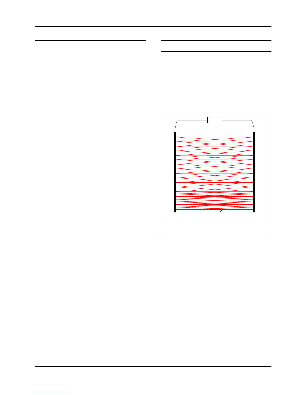
3. Function Descriptions
3.1 General
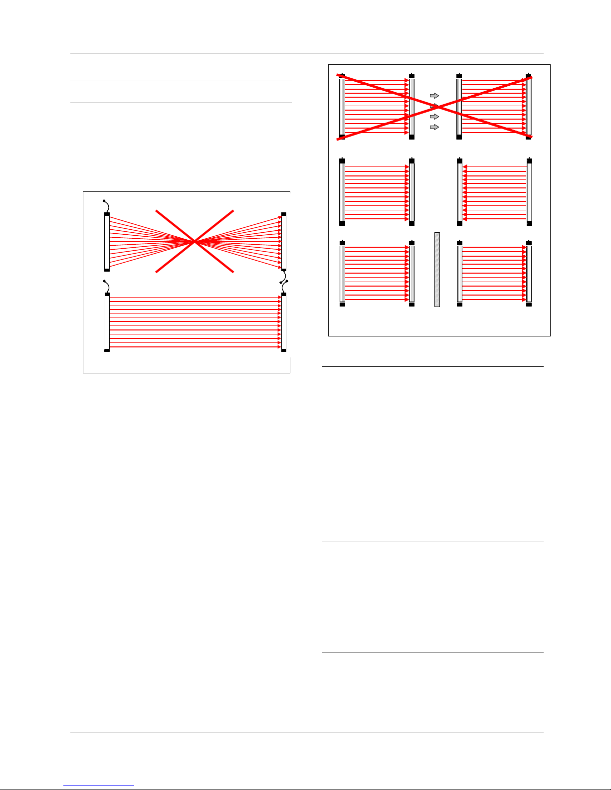
The accident prevention light curtain cegard/Lift LI
operates according to the principle of a through-beam
sensor. The monitoring is carried out using pulsed
infrared light. It consists of a transmitter edge, which
sends out many individual infrared beams. These
light beams are received by the receiver edge, are
converted into electrical signals and are transmitted
to the control unit light curtain. An interruption of a
light beam is then communicated to its outputs
(Figure 1).
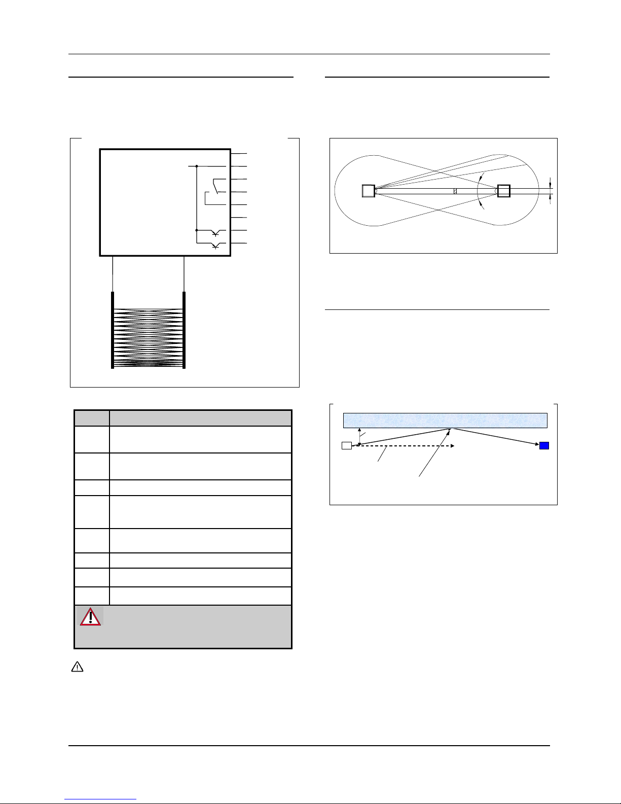
3.2. Calibration
In order to generate only as much emitted light as
necessary, the control unit light curtain performs a
calibration. During the calibration, the controller unit
measures how much emitter power is required for
every individual light beam to trigger the
corresponding receiver. This calibration prevents the
notorious reflection of through-beam sensor systems
as far as possible and replaces the usual process of
grouping the optical aperture angle near other light
curtains. This substantially simplifies installation and
alignment of the door edges.
The calibration process lasts between 0.5 and 2
seconds, depending on the distance between the
emitter and receiver edges. The calibration is
performed at power-up and by pressing the "T" button
on the control unit light curtain. If no changes occur in
the monitored area over a period of 30 minutes, i.e.
the elevator is at a standstill, the elevator controller
carries out a calibration automatically. Large
variations of illumination e.g. because of cleaning etc.
are detected within 3 seconds and recalibrated.