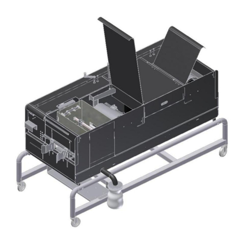
Ceetec SP 250 User manual

1/27
Users guide
- - - - -
Ceetec®SP 250

2/27
INDHOLDSFORTEGNELSE
1. Introduction................................................................................................................... 4
2. Safety Instructions......................................................................................................5
2.1 Use of machine........................................................................................................... 5
2.2 Clothing........................................................................................................................ 5
2.3 Personal protective equipment ................................................................................ 5
2.4 Fluids............................................................................................................................ 5
2.4.1 Water based wood protection ..........................................................................................................6
2.4.2 Oil based paint................................................................................................................................. 6
2.5 Room temperature..................................................................................................... 6
2.6 Ventilation.................................................................................................................... 6
2.7 Risks during use......................................................................................................... 6
2.8 Moving the machine................................................................................................... 6
3. Technical data..............................................................................................................7
4. Preparing the machine for use................................................................................8
4.1 Generally...................................................................................................................... 8
4.2 Emergency stop.......................................................................................................... 8
4.3 Stop .............................................................................................................................. 8
5. Adjusting the machine............................................................................................... 9
5.1 Overall.......................................................................................................................... 9
5.2 Back pressure roller................................................................................................... 9
5.3 Feeding with items..................................................................................................... 9
5.4 Nozzles ........................................................................................................................ 9
5.5 Brushes and screen/shield....................................................................................... 9
5.6 Forward drive............................................................................................................ 10
5.7 Test run and flow rate.............................................................................................. 10
5.8 Opening the lid.......................................................................................................... 11
6. Cleaning....................................................................................................................... 12
6.1 After use of water based products......................................................................... 12
6.1.1 All loose parts................................................................................................................................ 12
6.1.2 The machine................................................................................................................................... 12
6.2 After use of oil based products.............................................................................. 13
6.2.1 All loose parts................................................................................................................................ 13
6.2.2 The machine................................................................................................................................... 13
6.3 Thorough cleaning of the machine before re-use or colour shift......................... 15
7. Maintenance................................................................................................................ 16
7.1 V-belts, chains and toothed belts.......................................................................... 16
7.2 Forward drive toothed belt (pos. 9011-20526).................................................... 16
7.3 Chain to horizontal brushes (pos. 9016-20101).................................................. 16
7.4 Resetting the brush arms........................................................................................ 16
7.5 Pumps (Pos. 9011-20720)...................................................................................... 16

3/27
8. Replacing spare parts.............................................................................................. 17
9. Trouble shooting ....................................................................................................... 18
10. Spare part list............................................................................................................. 19
11. Production address .................................................................................................. 27

4/27
1. Introduction
The Ceetec SP 250 is built to treat wood with water and oil based wood protection products. It is suitable
for rough, planed and shaped wood. The machine is specially designed for the treatment of wood
material with a length of min. 300 mm, a height of max. 10 mm and a width of 250 mm max.
These wood materials are often named as shingles
Key factors of the Ceetec SP 250 are easy and safety of operation and maintenance.
The lids are hinged and the machine stops when a lid is opened. When the side panel, housing the
controls and lower protection caps are removed, it is easy to access the transmissions.
The machine is on rubber wheels, which is making it easy to move around.
Item numbers in brackets, in the following, refer either to accompanying pictures or to pictures located
on the final pages of this manual.

5/27
2. Safety Instructions
Important:
The following safety instructions must be adhered to for reasons of personal safety.
All users must be familiar with these user instructions. Read thoroughly before use to
know the machine functions entirely.
2.1 Use of machine
The machine is only to be used for treating wood with water and oil based wood protection products. The
machine is not intended as washing- or cleaning machine, using chemicals for degreasing, removal of
paint etc
Do not use the machine with particular dangerous, unhealthy or flammable liquids.
Do always comply with the instructions given in the supplier directions of the used substances.
Misuse may lead to strangling, unconsciousness, brain damage, fire or explosion followed by combustion
etc.
The machine is not constructed to be used in ATEX zone classified areas, and must NOT be used in zone
classified surroundings.
2.2 Clothing
Avoid loose fitting clothing and loose, dangling hair when operating the machine.
2.3 Personal protective equipment
Use rubber gloves and eye protection when adjusting and cleaning the machine.
The operator that receives treated items from the machine must wear rubber gloves.
Choice of protective equipment should follow the recommendations from the supplier directions of the
used paint.
2.4 Fluids
The used fluids – paints or cleaning products – must have a flash point at min. 10° C. above the
surrounding temperature. Do not use liquids with a flash point lower than 40° C due to the risk of fire.
Attention:
Use eye protectors and gloves when operating the machine. By accidents the operator is to act according
to the supplier directions of the used paint.
It is therefore important that this product information is available and is known and scrutinized!

6/27
2.4.1 Water based wood protection
E.g.: Tintex Tinova VX, Ready V40, produced by Akzo Nobel. Gori 11, Gori 356, Gori 410, Gori 411, Gori
413, Gori 417, Gori 892, Gori 894 all produced by Dyrup A/S.
2.4.2 Oil based paint
E.g.: Gori 22 wood primer, Gori 44 wood protection, Gori 88 semi-/full coverage wood protection, Gori
wood oil, Gori outdoor wood treatment, Gori 400, Gori 541, all produced by Dyrup A/S.
Fluids with a flash point lower than 40° C may not be used due to the risk of fire.
2.5 Room temperature
When using oil-based products, room temperature must not exceed 29° C, and it must stay minimum 10°
C below the flashpoint of the used fluids/paints due to the risk of fire.
Note: Oil based products do not bind optimally when applied at a room temperature exceeding 25° C.
2.6 Ventilation
The machine should only be used in well-ventilated rooms or outdoors if convenient. Moreover attention
about ventilation should be paid to the supplier recommendations of the used paints/fluids.
Treated items should be placed for drying in a ventilated place to avoid any obnoxious effects from the
solvents.
2.7 Risks during use
Keep hands, etc., away from the machine inlet when the machine is running to avoid the risk of crushing.
Likewise hands etc. should be kept away from the outlet, also here is there a risk of crushing.
2.8 Moving the machine
The machine can be moved around on the mounted rubber-wheels or by forklift. Before moving the
machine it must be checked that all fluids are drained off.
When moving by forklift: Be aware that the forklift lifts under the contrived lifting marks.
When moving manually: Be aware that all needless gear has been taken out of the machine, and the
machine is in god balance. Never try moving the machine manually on hilly ground.

7/27
3. Technical data
Type:
SP 250
Dimension:
Height: ca. 1.090 mm
Length: ca. 1.700 mm
Width: ca. 800 mm
Product number:
9016-20000
Motors, power connection
Effect, motor
Effect, pump
3x400 V + J - IP class: 54
0.55 kW
0.37 kW
Forward drive speed:
Approx. 16-42 m/min
Pump:
Approx. 20-25 L/min
Weight:
Approx. 200kg
Max. item dimensions:
Width: 250mm x Height: 10mm.
Min. item length:
300mm

8/27
4. Preparing the machine for use
4.1 Generally
Place the machine on a flat, firm surface. Lower the four support legs so that the machine stands stable.
The control panel can during transport have been placed under the machine to protect it from impact.
The control panel is mounted on the side of the machine before it is taking into use, using 4 screws.
Screw the adapter for the filter bag (item 9011-20519) onto the outlet pipe and hang the filter bag (item
9011-20517) on it. Put the bucket with paint/fluid underneath the filter bag. Remember to stir the fluid.
Place the suction and excess pressure hose (items 9011-20587 and 90-20585) in the bucket.
Connect the machine to the power source as prescribed.
The machine is attached to the power station following the local regulations. If it turns out to be
necessary changing the plug, the directions from the supplier must be followed. This job is only to be
done by a competent electrical specialist.
4.2 Emergency stop
Normally a person on each end operates the machine.
It is possible to operate with only 1 person. If that is the case, insert only max. 10 shingles, before
emptying the tray, which is installed at the machines end.
Activating the emergency stops, which are placed by the operator on both ends, can stop the machine.
When an emergency stop is activated the forward drive is stopped.
The pump continues pumping.
After activating the emergency stop, the machine can only be restarted by unlocking the emergency
stop and activating the start button again.
NB: Before starting the machine again be sure that the incident has come to an end, and that the reason
for activating the emergency stop is known.
4.3 Stop
During normal use the buttons ”Pump and ”Forward drive” put in stop position stops the machine.
When the machine is stopped, in order to be moved, repaired e.g. the main switch on the control panel
must be turned to position “0”. (Power is off.)

9/27
5. Adjusting the machine
Before any adjustment of the machine, the main switch on the control panel must be in position
"O". (The machine is disconnected from all power.)
During the work, the operator must use rubber gloves and eye protection. Check also product
sheet / safety data sheets for claims for other protective equipment.
5.1 Overall
Open the lid on the machine.
Set the nozzles, back pressure roller and brushes to the outer position. Feed the item into the machine.
NB: The machines forward drive can not be activated, as long as the lid is open.
5.2 Back pressure roller
The back pressure rollers prevent the lower horizontal brushes lifting thin items, likewise they ensure
that the item is lead forward in the machine, and not ”drifting” on the forward drive rollers. Adjust the
rollers by loosening the wing screws and moving them towards the item. When the machine is empty of
items, the back pressure rollers and the forward drive rollers shall be just above each other, but with out
touching.
5.3 Feeding with items
As previously described the machine is specially designed for the treatment of the wedge-shaped
shingles with the previous mentioned maximum and minimum dimensions. The items are always
brought into the machine with the thin end first. If this is not respected, there is a risk that the
backpressure rollers will prevent the items to run through the machine. This will lead to an accumulation
of items in the machine, with the risk of operation stop.
5.4 Nozzles
Place the nozzles (item 9011-20645) approx. 20 mm from the item. Advantageously the nozzles can be
placed, so they will point forward. This means that the item also gets treated at the end.
5.5 Brushes and screen/shield
Rotating brushes apply fluids evenly and brush off excess fluid.
The brushes are identical and made from organic horsehair.
The brushes are mounted and removed by screwing off a single star handle.
The brushes can be set tightly or loosely against the item, depending on treatment and the shape of the
item.
Adjust the horizontal brushes by putting the included pole into the square pipe on the brushes module.
The screen will stop spray coming from the brushes and dripping on to the finished surface. It must
therefore always be in placed before starting the machine.
Adjust the screens so that there is approx. 10 mm gap between the item and the front edge.

10/27
5.6 Forward drive
The forward drive propels the item through the machine. The backpressure rollers ensures that the item
don’t ”drift” on the 4 forward drive rollers. The pressure on the backpressure rollers is spring-loaded. The
height on these rollers can be adjusted by loosen the star handle and moove the backpressure roller
and the frame up or down.
5.7 Test run and flow rate
1. Pull the item out.
Close the lid.
Check that the bucket containing wood protection is underneath the outlet pipe, and that the suction and
excess pressure hose are placed in the bucket. Close the lid on forward drive and brushes.
Position the main switch on the control panel to "I" (power is connected). Activate the button "PUMP"
and the pumps will begin to pump. Spraying may occur.
Ensure that all valves (pos. 9011-20593) are closed. Adjust the nozzles to the desired position. Adjust
the fluid amount using the nozzle valves.
Be aware of not to apply to much wood treatment, as this can lead to dripping finished items and/or
”runners” on the items.
Always open the upper nozzle first. The machine can treat 1 or 2 sides of the item at the same time.
Only open fluid nozzles for those sides that are to be treated.
2. Activate the "FORWARD DRIVE" button and adjust the forward drive to the desired speed. The flow
rate can be varied steplessly, and be regulated by turning the spindle using the handle.
Turning clockwise: Slower speed
Turning anti-clockwise: Faster speed
3. Activate the button ”Børster/Brushes” and adjust the brush pressure as previously described.
Feed the item into the inlet and check that the forward drive is running evenly.
If forward drive is not running evenly, adjust the back pressure roller.
The item can stop moving if it hits nozzles or brushes. In that case they should be re-adjusted.
Test drive with the same item 2-3 times. This ensures that the brushes get wetted. Then make a test
drive with a new item. If the result is fine, production can start. The items should be controlled regularly,
to ensure a satisfying result.

11/27
5.8 Opening the lid
NOTE: THAT THE PUMPS CAN BE ACTIVATED EVEN WHEN THE LID IS OPEN.
Attention: The lid on the forward drive and brushes is hinged and can be opened. The lid is connected to
a switch that stops the forward drive, if the lid is open. The pump however, is not connected to this
switch and will therefore not stop when the lid is opened.
To start the forward drive the lid must be closed. If the lid is opened while the machine is activated the
forward drive stops immediately. To restart the machine the lid must be closed and a new start
command must be given on the start button.

12/27
6. Cleaning
6.1 After use of water based products
After daily use or when changing colour, it is important that the machine is thoroughly cleaned.
Due to safety it is important that signs and handles are kept clean and free of paint.
NB: Rubber gloves and eye protection must be used during the cleaning of the machine. Please follow
the directions from the supplier of the cleaning products.
6.1.1 All loose parts
Wash down the brush screens, brushes, backpressure rollers, and guide with water, preferably hot
water.
It is recommended a more thorough cleaning of loose parts before re-use or when changing colours.
The procedures for cleaning these parts are described below:
First clean the loose parts are described above.
Soak the parts in a mixture of 50% cleaning solution and 50% water.
It is important that the brushes are always stacked on "hub" of the brush to prevent the hairs being bent
out of shape.
Rinse the parts thoroughly in water before re-use.
6.1.2 The machine
Take the suction pipe out of the bucket of wood protection.
Start the pump. Open the nozzle valves (remember to always open the upper nozzles first). Remove the
end plugs from the nozzles and the last of the fluid will be pumped into the machine and return to the
bucket. Close the nozzle valves after approx. 2 min.
The nozzle system is empty when air is pushed out of the excess pressure valve (seen as air bubbles in
the bucket).
Remount the end plugs onto the nozzle tubes. Replace the bucket with one bucket of 10 l.
(approximately 2,5 gal.) of clean water and one empty bucket.
Place the suction tube into the bucket of water and the excess pressure hose into the empty bucket
underneath the drain.
Start the pump and open the nozzle valves (remember to always open the upper nozzles first).
Close the nozzle valves when clean water starts coming out of the nozzles.
Rinse the machine with clean water and a brush, if necessary.
Finally, clean the filter bag, suction filter and excess pressure valve.

13/27
6.2 After use of oil based products
After daily use or when changing colour, it is important that the machine is thoroughly cleaned.
Due to safety it is important that signs and handles are kept clean and free of paint.
NB: Rubber gloves and eye protection must be used during the cleaning of the machine. Please follow
the directions from the supplier of the cleaning products.
6.2.1 All loose parts
Wash down the brush screens, brushes, backpressure rollers and guide in water, preferably hot water, if
necessary, cleaning solution.
It is recommended a more thorough cleaning of loose parts before re-use or when changing colours.
The procedures for cleaning these parts are described below:
First clean the loose parts are described above.
Soak the parts in a mixture of 50% cleaning solution and 50% water.
It is important that the brushes are always stacked on "hub" of the brush to prevent the hairs being bent
out of shape.
Rinse the parts thoroughly in water before re-use.
6.2.2 The machine
Take the suction pipe out of the bucket of wood protection.
Start the pump. Open the nozzle valves (remember to always open the upper nozzles first). Remove the
end plugs from the nozzles and the last of the fluid will be pumped into the machine and return to the
bucket. Close the nozzle valves after approx. 2 min.
The nozzle system is empty when air is pushed out of the excess pressure valve (seen as air bubbles in
the bucket).
Remount the end plugs onto the nozzle tubes. Replace the bucket with 1 bucket of cleaning solution.
Never use cellulose thinner, toluene or strong solvents for cleaning, as they may dissolve the paint and
plastic parts.
Place the suction tube into the bucket.
Start the pump and open the nozzle valves
Close the nozzle valves when they are clean.
Rinse the machine with the inbuilt washing hose and a brush, if necessary.
Repeat the treatment if necessary.

14/27
The cleaning solution can be re-used several times. Remember to rinse with clean cleaning solution
afterwards.
Dry the exterior of the machine with a damp cloth – dampened with cleaning solution.
Empty the machine of cleaning solution.
Finally clean the filter bag, suction filter and excess pressure valve, the same way you did it with the
loose parts.
Where water based products are to be used following cleaning, the machine must be rinsed through
with water.

15/27
6.3 Thorough cleaning of the machine before re-use or colour shift.
First clean the machine as described in section 6.1 or 6.2
Replace the buckets with a bucket of cleaning solution. The suction tube and the excess pressure hose
are placed in the bucket. Start the pump. With the build-in washing hose and if necessary a brush, wash
the machine.
NOTE: The machine has to be rinsed with cleaning solution in 5-10 min. before it will work.
If necessesary, repeat the treatment. The used cleaning fluid can be re-used several times.
Dry the exterior of the machine with a damp cloth – dampened with cleaning solution.
Empty the machine of cleaning solution, and rinse it with water.
NOTE: The machine has to be clean from all cleaning solution, otherwise it will dissolve the paint on the
machine.
Finally clean the filter bag, suction filter and excess pressure valve, the same way you did it with the
loose parts.

16/27
7. Maintenance
Switch the main switch to "0" and unplug before commencing maintenance work.
Removing the side panel and/or the lower protective caps easily accesses all adjustable
mechanical parts.
Do NOT start the machine before all safety guards are put back into place.
7.1 V-belts, chains and toothed belts
Tighten the v-belts and chains after approx. 14 days of use.
All grease nipples must be regularly greased with a grease gun.
The v-belts and toothed belts are supplied with tighten rollers and must be checked at least once a year
or after 1700 hours of operation.
7.2 Forward drive toothed belt (pos. 9011-20526)
Loosen the screws on the motor plate and tighten until the belt is taut.
7.3 Chain to horizontal brushes (pos. 9016-20101)
Tighten by loosening the screw and changing position of sprocket wheel (pos. 9011-20559)
7.4 Resetting the brush arms
If the brush axle (pos. 9011-20510) has moved its setting or if the turn plate is leaking, it must be
tightened. The turn plate is bolted with 3 self-locking nuts. These must be tightened. If the turn plate is
still leaking after the executive of the above, replace the O-ring (pos. 9011-20591)
7.5 Pumps (Pos. 9011-20720)
There are two types of electric pumps, (Mono) or Ceetec membrane pumps. The oil in the gear motor of
each type of pump must be changed for the first time after 700 hours, and then after every 8000 hours.

17/27
8. Replacing spare parts
Switch the main switch to "0" and unplug before replacing any parts.
Removing the side panel, shield on the rear and/or the removing the lower protection cap can easily
access all replaceable parts.
When the adjustments are done, assembling is done in reverse order. Do NOT start the machine
before all safety guards are put back into place.
Motor v-belt – intermediate shaft I (pos. 9011-20575)
Loosen the motor (pos. 9011-20563) and move it.
Chain for intermediate shaft I - horizontal brushes (pos. 9016-20101)
First loosen the tighten roll (pos. 9011-20559) then the chain can be removed.
Forward drive toothed belt (pos. 9011-20526)
Loosen the motor plate and remove the v-belt.
Replacement of the pumps diaphragms
The bottom threaded hose couplings are loosened.
The bolts (item D) are loosened.
The straps (item G) as well as the pump caps (pos.9011-20721) are dismantled.
The bolts (item E) are loosened and the diaphragms can now be replaced.
When dismantling its important to seal the screws (item E) (Teflon tape can be used) and to
make sure that the diaphragms and caps are placed in the recess (the middle)
NB: A set of diaphragms consists of 2 black and 1 yellow diaphragms. The yellow diaphragm
must be turned towards the pumps middle.

18/27
9. Trouble shooting
Fault
Possible cause
Action
A. Pumps/forward drive/brushes will
not start.
The machine is not connected to the
power source.
The main switch is turned off.
There has been a thermal cut-out.
Connect the power.
Switch the main switch to position ”I”
Check the frequency converter in
the electrics cabinet.
B. Forward drive roller and brushes
are not rotating.
The power supply to the motor for
the forward drive is interrupted.
The V-
belts/toothed belts are too
loose or damaged.
A belt is broken.
The forward drive roller, V-
belt/pulley is not fastened to the
axel.
See ”A”
Tighten/replace the belt (-s)
Replace the belts or chains.
Fasten the pulley.
C. No, or too little, liquid is coming
out of the nozzles.
The power supply to the motor for
the pumps is interrupted.
The nozzle valves are shut.
Grime in the suction filter.
The nozzles are blocked.
The springs in the excess pressure
valve may be too loose.
See ”A”
Open the nozzle valves.
Unscrew the filter strainer and clean.
If necessary, blow clean pressurised
air through it.
Remove and clean the flow nozzles
and end plugs.
Clean the nozzle hoses.
Check all the hoses for dirt.
Ensure that the hose couplings are
tightened and sealed so that the
pump does not suck in "false" air.
Open all the nozzle valves.
Take the excess pressure valve out
of the bucket. If lots of fluid comes
out, the spring n
eeds tightening
(lengthening).
D. The motor for the pumps cuts
out.
The motor is overloaded because
the excess pressure valve is
blocked
Clean the excess pressure valve
and hoses. When assembling the
excess pressure valve, the grey
gauge block must face
in towards
the valve. Wait approx. 10 minutes
and then reset the pump motor.
E. The motor for forward
drive/brushes cuts out.
The motor is overloaded because
the backpressure roller and/or
brushes are too tightly adjusted up
to the item.
Adjust the setting.
Wait approx. 10 minutes and then
reset the forward drive motor.

19/27
10. Spare part list
Item number
Pcs. per machine
Description
9016-20101
1
Chain for brushes
9011-20559
6
Sprocket wheel 15 T with 2 bearings
9015-20536
1
Handle for backpressure roller
9011-20537
1
V-belt pulley A210 speed-changer contra disc
9011-20440
1
Arm for speed-changer
9011-20526
1
V-belt feed
9011-20539
1
V-belt feed
9011-20525
1
V-belt- speed-changer

20/27
Item number
Pcs. per machine
Description
9011-20554
2
Support bearing for middel axe
9016-20102
1
Countershaft for SP250
9011-20557
5
Sprocket wheel 20 T countershaft I
9011-20577
1
Sprocket wheel 36 T on countershaft I
9011-20575
1
Chain to engine / countershaft I
9011-20528
1
Speed-changer
9011-20563
1
Engine for forward drive (Inform if cULus approved model
is wanted)
9011-20564
1
Pump engine (Inform if cULus approved model is
wanted)
Table of contents
Other Ceetec Paint Sprayer manuals