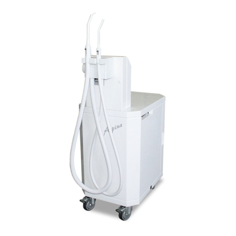
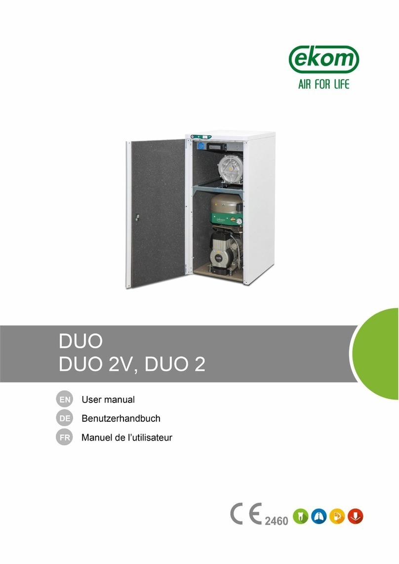
EKOM DO 2.1 User manual


DENTAL SUCTION UNIT
DENTALABSAUGPUMPE
L’ASPIRATEUR DENTAIRE
ДЕНТАЛЬНЫЙ АСПИРАТОР
POMPA SSĄCA
DENTÁLNA ODSÁVAČKA
DENTÁLNÍ ODSÁVAČKA
DO2.1
DO2.1-10
EKOM spol. s r. o.
Priemyselná 5031/18
SK-921 01 Piešťany
Slovak Republic
tel.: +421 33 7967255
fax: +421 33 7967223
www.ekom.sk
DATE OF LAST REVISION
DATUM DER LETZTEN ÜBERARBEITUNG
DATE DE LA DERNIÈRE RÉVISION
ДАТА ПОСЛЕДНЕЙ РЕДАКЦИИ
DATA OSTATNIEJ AKTUALIZACJI
DÁTUM POSLEDNEJ REVÍZIE
DATUM POSLEDNÍ REVIZE08/2018
NP-DO2.1_10_08-2018
112000005-000

CONTENTS................................. 1
INHALT....................................... 12
TABLES DES MATIÈRES.......... 23
ОГЛАВЛЕНИЕ............................ 38
SPIS TREŚCI.............................. 45
OBSAH....................................... 56
OBSAH………............................. 67

DO 2.1
DO 2.1-10
08/2018 - 1 - NP-DO2.1_10_08-2018
CONTENTS
IMPORTANT INFORMATION................................................................................................................. 2
1. CONFORMITY WITH THE REQUIREMENTS OF EUROPEAN UNION DIRECTIVES............ 2
2. INTENDED USE......................................................................................................................... 2
3. CONTRAINDICATIONS AND SIDE-EFFECTS ......................................................................... 2
4. WARNINGS AND SYMBOLS..................................................................................................... 2
5. WARNINGS................................................................................................................................ 3
6. STORAGE AND TRANSPORT.................................................................................................. 5
7. TECHNICAL DATA..................................................................................................................... 5
8. PRODUCT DESCRIPTION........................................................................................................ 6
9. DESCRIPTION OF FUNCTION ................................................................................................. 7
INSTALLATION....................................................................................................................................... 7
10. USE ............................................................................................................................................ 7
11. INSTALLATION.......................................................................................................................... 7
12. WIRING DIAGRAM .................................................................................................................... 9
13. FIRST OPERATION................................................................................................................... 9
OPERATION ........................................................................................................................................... 9
14. SWITCHING SUCTION UNIT ON.............................................................................................. 9
MAINTENANCE .................................................................................................................................... 10
15. MAINTENANCE SCHEDULE................................................................................................. 10
16. MAINTENANCE ....................................................................................................................... 10
17. STORAGE................................................................................................................................ 10
18. DISPOSING OF THE APPLIANCE.......................................................................................... 10
19. REPAIR SERVICE ................................................................................................................... 11
20. SOLVING PROBLEMS............................................................................................................. 11
ANNEX .................................................................................................................................................. 78
21. INSTALLATION RECORD ....................................................................................................... 78

DO 2.1
DO 2.1-10
NP-DO2.1_10_08-2018 - 2 - 08/2018
IMPORTANT INFORMATION
1. CONFORMITY WITH THE REQUIREMENTS OF EUROPEAN UNION DIRECTIVES
This product conforms to the requirements of the Medical Device Directive (93/42/EEC), and is
safe for the intended use if all safety instructions are followed.
2. INTENDED USE
Dental suction unit DO 2.1 - is the source of vacuum to provide suction in the dental surgery –aspirates
waste from the patients mouth - via a tip connected to the cannule of the suction hose, through the
pneumatic control module and down to the separator, where the water and foreign matter is left behind,
leaving only air to be drawn (sucked) to the suction unit and exhausted away from the surgery’s
environment.
Any other use of the product beyond its intended use is considered an incorrect use. The
manufacturer is not liable for any damages or injuries resulting from the incorrect use.
3. CONTRAINDICATIONS AND SIDE-EFFECTS
There are no contraindications or side-effects known.
4. WARNINGS AND SYMBOLS
The following symbols are used in the user manual, device and its packaging to denote important
details and information:
General warnings
Danger, electric shock hazard
Read the user manual!
CE-marking
Caution! Hot surface
Ground connection
Terminal for ground connection
Alternating current
Handling mark on package –FRAGILE
Handling mark on package –THIS SIDE UP
Handling mark on package –KEEP DRY

DO 2.1
DO 2.1-10
08/2018 - 3 - NP-DO2.1_10_08-2018
Handling mark on package –TEMPERATURE LIMITATIONS
Handling mark on package –LIMITED STACKING
Mark on package –RECYCLABLE MATERIAL
Manufacturer
Danger of biological hazard
5. WARNINGS
The product is designed and manufactured to be safe for the user and the surrounding
environment when used in the defined manner. Keep the following warnings in mind.
5.1. General warnings
READ THE USER MANUAL CAREFULLY BEFORE USING THE DEVICE AND KEEP IT FOR
FUTURE USE!
The user manual supports the correct installation, operation and maintenance of the product.
Careful review of this manual will provide the information necessary for the correct operation of
the product for its intended use.
Original packaging should be retained for the return of the device. Only the original packaging
ensures protection of the device during transport. If it is necessary to return the product during
the warranty period, the manufacturer is not liable for damages caused by improper packaging.
This warranty does not cover damages originating from the use of accessories other than those
specified or recommended by the manufacturer.
The manufacturer only guarantees the safety, reliability and function of the device if:
-installation, new settings, changes, expansion, and repairs are performed by the
manufacturer or an organisation authorised by the manufacturer.
-the product is used pursuant to the user manual.
The user manual corresponds to the configuration of the product and its compliance with the
applicable safety and technical standards at the time of printing. The manufacturer reserves all
rights for the protection of its configuration, methods and names.
Translation of the user manual is performed in accordance with the best available knowledge.
The Slovak version is to be used in the event of any uncertainties.

DO 2.1
DO 2.1-10
NP-DO2.1_10_08-2018 - 4 - 08/2018
5.2. General safety warnings
The manufacturer designed and manufactured the product to minimise all risks when used
correctly for the intended use. The manufacturer considers it its obligation to lay down the following
general safety precautions.
Use and operation of the product must comply with all laws and local regulations valid in the
place of use. The operator and user are responsible for following all the appropriate regulations
in the interests of performing work safely.
Only the use of original parts guarantees the safety of operating personnel and the flawless
operation of the product itself. Only the accessories and parts mentioned in the technical
documentation or expressly approved by the manufacturer should be used.
The operator must ensure that the device is functioning correctly and safely before every use.
The user must be familiar with the operation of the device.
Do not use the product in environments with a risk of explosion.
The user must inform the supplier immediately if any problem directly related to the operation of
the device occurs.
5.3. Safety warnings on protection from electric current
The device must only be connected to a properly installed, earthed socket.
Before the product is plugged in, ensure that the mains voltage and frequency stated on the
product are in compliance with the values of the mains.
Prior to putting the device into operation check for any damage to the connected pneumatic
lines and electrical wiring. Replace damaged pneumatic lines and electrical wirings immediately.
Immediately disconnect the product from the mains (remove power cord from the socket) in
hazardous situations or in the case of a technical malfunction.
During all repairs and maintenance, ensure that:
-the mains plug is removed from the power socket
-pressure is vented from pipes
The product shall only be installed by a qualified technician.

DO 2.1
DO 2.1-10
08/2018 - 5 - NP-DO2.1_10_08-2018
6. STORAGE AND TRANSPORT
The manufacturer provides sufficient protection of the appliance when it leaves the factory. Therefore the
product is protected against damage during storage and transport
Caution! For transport, always use the original packaging and, transport the appliance in
the upright position, using secure fixings.
Keep dry. Protect appliance against humidity and extreme temperatures during storage and
transport. Appliance in the original packaging must be stored in warm, dry and dust-free areas.
Keep packaging material if possible. If not, please dispose of the packaging material in an
environmentally friendly way. Cardboard can be recycled.
7. TECHNICAL DATA
DO 2.1 (*T)
DO 2.1 Z(*T)
DO 2.1-10 (*T)
DO 2.1-10 Z(*T)
Rated voltage / frequency
V / Hz
230 / 50
230 / 60 (*)
Performance of suction unit
under-pressure 5kPa
ltr.min-1
800
Min. under-pressure of
suction unit
kPa
12
Appliance current
A
2.6
Noise level
dB(A)
46
58
46
58
Duty cycle
permanent - S 1
Dimensions of appliance
w x d x h mm
380x525x575
290x430x350
420x525x620
330x430x350
Dimensions of appliance in
cardboard w x d x h
mm
410x555x650
350x460x450
490x555x780
350x460x450
Weight of appliance
Kg
27
15
29
15
Weight of appliance in
cardboard
Kg
29
18
31
18
Version according to
EN 60 601-1
class I.
Notes: (*) –Rated voltage / frequency by special request
(**) –by special request

DO 2.1
DO 2.1-10
NP-DO2.1_10_08-2018 - 6 - 08/2018
Climatic conditions during storage and transport
Temperature: –25°C to +55°C. 24 h to +70°C
Relative air humidity: 10% to 90 % (no condensation)
Climatic conditions of operation
Temperature: +5°C to +40°C
Relative air humidity: 70%
7.1. FAD efficiency correction for differences in elevation
FAD correction table
FAD efficiency refers to conditions at an elevation of 0 mamsl: Temperature: 20°C
Atmospheric pressure: 101325 Pa
Relative humidity: 0%
8. PRODUCT DESCRIPTION
Dental suction unit is composed of an aspirator unit with a base, cooling fan, switching block and an
insulated soundproof box. Operation of the suction unit is controlled via (24V/0.1A DC/AC) connection at the
chair or via a switch on (model „T“) at the suction unit. Cooling fan draws air into the box and circulates it
around the suction unit forcing air out through ventilated slots in the rear.
8.1. Variants
Dental suction units are made accordingly for the purpose in the following versions:
DO 2.1, DO 2.1-10 –stationary dental suction unit in a soundproof box –it serves as the source of vacuum
for the dental chair fitted with a pneumatic control module. The suction unit will start automatically after
receiving a signal from the chair –by a 24V AC/DC connection between the chair and suction unit.
Soundproof box is provided for silent operation.
DO 2.1 T, DO 2.1-10 T –model as at DO 2.1 above, switch from unit controlls suction pump by voltage from
module „T“.
DO 2.1 Z, DO 2.1-10 Z –stationary dental suction unit without the soundproof box –it serves as the source
of vacuum for the dental chair fitted with a pneumatic control module. The suction unit will start automatically
after receiving a signal from the chair - by a 24V AC/DC connection between the chair and suction unit.
DO 2.1 TZ, DO 2.1-10 TZ –model as at DO 2.1 Z above, switch from unit controlls suction pump by voltage
from module „T“.
Dental suction units above designated as - DO 2.1-10, DO 2.1-10 T - are different from the other
ones only by their dimensions and weight, so that they complied with the design of compressors -
DK50-10 S type.
Elevation [mamsl]
0 - 1500
1501 - 2500
2501 - 3500
3501 - 4500
FAD [l/min]
FAD x 1
FAD x 0.8
FAD x 0.71
FAD x 0.60

DO 2.1
DO 2.1-10
08/2018 - 7 - NP-DO2.1_10_08-2018
9. DESCRIPTION OF FUNCTION
Suction pump (1) (Fig.1) creates vacuum in the
pneumatic control module thus it aspirates foreign
matters away from the working area of the physician and
sucks them into the separator at the dental chair. Only
clean air continues past the separator through the pump
of the suction unit, and then, is pushed through a
supplementary silencer (6) and continues through the
output hose and vented to the environment outside of
the building. Suction unit is switched on by means of a
switching block (3) after receiving a signal from the
dental chair (voltage 24V AC/DC) or by switching-on at
the suction unit (switch - model „T“). Suction pump is
mounted above the cooling fan (4)which is fixed to the
base (5). The cooling fan draws air into the insulated
soundproof metal box (2), which stands on feet to allow
the air in, and vented slots in the rear to allow the air to
blow through.
Make sure that nothing impedes the free flow of air under and around the compressor.
Never cover the hot air outlet on the top back side of the case.
If placing the appliance onto a soft floor, such as carpet, it is important to create a gap
between the base and floor or the box and floor, e.g. underpin the footings with hard pads.
The cooling fan needs a gap to draw air inside the box.
INSTALLATION
10. USE
The appliance must be installed and operated in a dry, well ventilated and dust-free area where ambient
temperature is within the range of +5°C to +40°C and relative air humidity does not exceed 70%. The
appliance must be installed so that it is accessible at all times to operate and maintain. Please ensure the
appliance label is accessible also.
The appliance must stand on a flat, sufficiently stable base. See paragraph 5 (Technical data) when
positioning or lifting the appliance.
Aspirators must not be exposed to external environments. They must not be in operation in moist or wet
environments. Furthermore, it is forbidden to use them in premises, where there is the presence of
explosive gases or flammable liquids.
Prior to installation of the aspirator to medical equipment, it is important to ensure that the medium
available meet, the requirements fit for the purpose of use. With regards to this, respect the technical data
provided. Classification and evaluation of compliance should be carried out at the installation stage.
For any other use beyond the above scope will be considered unfit for the aspirator’s purpose, and
therefore, the manufacturer is not responsible for damages resulting from them. Risk is borne exclusively
by the operator/user.
11. INSTALLATION
Only qualified personnel can install this appliance and by obligation, train all operating
personnel on the correct use and routine maintenance. Installation and training of all
operators shall be confirmed by their signature on the certificate of installation.
Prior to installation, ensure the appliance is clear of all the transport packaging and fixings
to avoid any risk of damage to the product.
Fig.1

DO 2.1
DO 2.1-10
NP-DO2.1_10_08-2018 - 8 - 08/2018
Fig.3
Fig.2
Caution! Contact with the appliance is dangerous. High temperatures occur during and
after use. Beware of hot surfaces and the danger of fire if, contact is made by flammable
objects
At a predetermined place, position the suction unit on the base (Fig.2) and remove all transport packaging
and fixings. Connect both hoses to their relative inlet and outlet ports of the pump. Prepare the required
electrical connection between the pneumatic control module and suction unit as below:
Connections under floor –suitably shorten both hoses and
connect them to the prepared pipes protruding up through the
hole in the base. Connect the 24V signal wire from the dental
chair to the terminals –1 & 2 –and connect the power cord to
terminals - PE & U & N - inside the switching block.
Connection above floor –direct power cord and both hoses to
the rear of the base. Thread the 24V signal wire from dental
chair through the rear hole of the box and connect to the
terminals in the switching block. Position the box to face the
right direction, and place over the suction unit whilst at the
same time, thread both hoses and power cord through the rear
hole of the box. When positioned correctly, plug the power cord
in the electrical socket.
NOTE:
1 - Outline of the case
2 - Outline of the base
3 - Front of the case
4 - Suction pump control voltage (2X x 0.75)
5 - Suction pump - IN
6 - Suction pump - OUT
7 - Supply voltage - 230V/50(60) Hz, (3G x 0.75 x 3000)
All dimensions are in millimetres
Distance of box from wall - min. 80 mm
Outline dimensions for DO2.1-10 are listed in brackets
11.1. Vacuum Connection
Two hoses, one for suction (1) and one for exhaust (2) are
connected to the suction pump (Fig.3). The hoses are inlet
(1) and outlet (2) of the pump. They protrude through the
rear hole of the box, or they are connected to the pipe-work
under the floor. Suction (vacuum) hose is connected to the
separator/pneumatic control module at the dental chair, and
exhaust hose is vented away from the surgery to the
environment outside of the building.
11.2. Electrical connection
Plug the electrical cord into the mains.
The appliance is equipped with a grounded plug. Make sure this connection complies with
local electrical codes. The mains voltage and frequency must comply with the data stated
on the appliance label.
Keep the socket easily accessible to ensure that in an emergency the appliance can be safely
disconnected from the mains.
Connection to the power distribution box must be max.16 A.
Power between the suction unit and pneumatic control module on the dental chair, is 24V provided by
wires connecting to a PCB in the switching block (CP1).
If any electrical cord or air hose is damaged it must be replaced immediately.
1
2

DO 2.1
DO 2.1-10
08/2018 - 9 - NP-DO2.1_10_08-2018
Mark
Name
M1
Suction pump
EV1
Fan
CP1
Switching block
UN2
X1 1
UPEN
EV1 M1
1M
B1
C
54
X2
PS-DO2
(PST-DO2)
CP1
UN2
X1 1
54
X2
PS-DO2
C1 D1
+
Re1
FU1 FU2
UN2
X1 1
54
X2
PST-DO2
C1
D1
+
Re1
FU1 FU2
Tr1
24V AC/DC
or EXT.
12. WIRING DIAGRAM
13. FIRST OPERATION
Make sure that all stabilizers used during transport were removed.
Check all connections of the vacuum and exhaust pipe-work system.
Check the suction unit is switched on at the plug.
Check the suction unit switches on at the dentist‘s pneumatic control module.
OPERATION
In case of emergency, disconnect the suction unit from the mains (pull out the mains
plug).
Parts of the suction unit can have hot surface areas. There is the danger of scorching if
contact is made.
The suction unit operates after receiving a signal from the dental chair. The cooling fan
and suction pump always work together.
14. SWITCHING SUCTION UNIT ON
When the suction unit is switched on at the plug, power is provided to the switching block, and puts the
aspirator - on stand-by mode - waiting for a signal from the dental chair. When a signal is received, the
suction unit operates and creates a vacuum in the inlet path until a signal interrupts its operation, and puts
the suction unit back - on stand-by mode.
230 V
ELECTRIC OBJECT OF
CLASS I

DO 2.1
DO 2.1-10
NP-DO2.1_10_08-2018 - 10 - 08/2018
MAINTENANCE
15. MAINTENANCE SCHEDULE
Notice!
The operating entity is obliged to ensure that all tests of the equipment are carried out repeatedly at
least once within every 24 months (EN 62353) or in intervals as specified by the applicable national
legal regulations. A report must be prepared on the results of the tests (e.g.: according to EN 62353,
Annex G), including the measurement methods used.
Required maintenance
See document
Frequency
Performed by
• Separator - working correctly
( suction path free of liquids –dry )
Documentation
of dental unit
monthly
user
• Full service of suction system
Service
documentation
yearly
qualified
engineer
• Perform “Repeated Test” according
to EN 62353
chap.13
1 x 2 years
qualified
engineer
16. MAINTENANCE
Repair work beyond normal maintenance can be performed only by qualified personnel or
the manufacturer’s representative.
Use only spareparts and accessories approved by the manufacturer.
Prior to any maintenance or repair work, switch off the compressor and disconnect it from
the mains (pull out the mains plug).
Prior to any maintenance or repairs, the soundproof box must be removed.
The suction unit is designed and manufactured to keep maintenance to a minimum.
17. STORAGE
If the appliance is not to be used for a prolonged period of time, the manufacturer recommends operating the
entire aspirating system for approximately 10 minutes, with an unrestricted flow of air (without cannules).
Then disconnect the appliance from the mains. Cover the inlet and outlet ports with the plastic plugs that
were supplied with the unit
18. DISPOSING OF THE APPLIANCE
Disconnect appliance from the mains.
Disconnect appliance from pipe-work at the inlet and outlet ports.
To follow the rules of personal hygiene for works with contaminated material.
To separate, label, packing and providing for decontamination of contaminated parts by course of national
regulations.
Liquidate dental suction unit according to local effectives statutes.
This appliance has no negative impact on the environment when scrapped due to failure.
Inside parts of unit can be contaminated with biological material by reason incorrect using.
Before clearing and waste disposal pass on special institution for decontamination.

DO 2.1
DO 2.1-10
08/2018 - 11 - NP-DO2.1_10_08-2018
19. REPAIR SERVICE
Guaranteed and post-guarantee repairs must be done by the manufacturer, its authorized representative, or
service personnel approved by the supplier.
The manufacturer reserves the right to make changes to the appliance without notice. Any changes made
will not affect the functional properties of the appliance.
20. SOLVING PROBLEMS
Prior to any inspection or repair work to the appliance, disconnect from the power supply
–Switch off, remove plug from the mains socket.
The following must only be performed by trained engineers approved by the, supplier or manufacturer.
In case of repair of parts of device which might be contaminated please follow bellow mentioned instruction:
To follow the rules of personal hygiene for works with contaminated material. To separate,
label, packing and providing for decontamination of contaminated parts by course of
national regulations.
To perform the repair of damaged parts
FAILURE
POSSIBLE CAUSE
REMEDY
Suction unit does not
work
No voltage in the socket
Blown fuse in switching block
Faulty power cord
No presence of control voltage
Suction unit is/was flooded with liquid
Switch on circuit breaker, replace fuse
Replace faulty fuse
Replace faulty cord
Check power cord
Check signal from dental chair
Service/repair suction unit, adhere to
rules on work with infectious material
Damaged windings of motor, damaged
thermal protection
Faulty capacitor
Replace motor
Replace condenser / capacitor
Suction unit is noisy
Object in intake path
Suction unit is/was flooded with liquid
Remove foreign object
Service/repair suction unit, adhere to
rules on work with infectious material
Suction unit aspirates
poorly
Leaks in the inlet path
Object in inlet/outlet paths
Cure leaks in the inlet path, remove
foreign object

DO 2.1
DO 2.1-10
NP-DO2.1_10_08-2018 - 12 - 08/2018
INHALT
WICHTIGE INFORMATIONEN..............................................................................................................13
1. ÜBEREINSTIMMUNG MIT DEN ANFORDERUNGEN DER EU-RICHTLINIEN .....................13
2. BESTIMMUNGSGEMÄßE VERWENDUNG ............................................................................13
3. GEGENANZEIGEN UND NEBENWIRKUNGEN......................................................................13
4. WARNHINWEISE UND -SYMBOLE ........................................................................................13
5. WARNHINWEISE.....................................................................................................................14
6. LAGERUNG UND TRANSPORT .............................................................................................16
7. TECHNISCHE DATEN.............................................................................................................16
8. PRODUKTBESCHREIBUNG ...................................................................................................17
9. FUNKTIONSBESCHREIBUNG................................................................................................18
INSTALLATION .....................................................................................................................................18
10. NUTZUNGSBEDINGUNGEN...................................................................................................18
11. PRODUKTINSTALLATION.......................................................................................................19
12. SCHALTPLÄNE........................................................................................................................20
13. ERSTE INBETRIEBNAHME.....................................................................................................20
BEDIENUNG..........................................................................................................................................21
14. EINSCHALTEN DES GERÄTES..............................................................................................21
WARTUNG ............................................................................................................................................21
15. WARTUNGSINTERVALLE.......................................................................................................21
16. WARTUNG ...............................................................................................................................21
17. LAGERUNG..............................................................................................................................21
18. ENTSORGUNG DES GERÄTES .............................................................................................22
19. INFORMATIONEN ÜBER REPARATURBETRIEBE ...............................................................22
20. FEHLERSUCHE UND FEHLERBEHEBUNG...........................................................................22
ANHANG................................................................................................................................................78
21. INSTALLATIONSPROTOKOLL................................................................................................79

DO 2.1
DO 2.1-10
08/2018 - 13 - NP-DO2.1_10_08-2018
WICHTIGE INFORMATIONEN
1. ÜBEREINSTIMMUNG MIT DEN ANFORDERUNGEN DER EU-RICHTLINIEN
Dieses Produkt erfüllt die Anforderungen der Medizinproduktrichtlinie (93/42/EEG) und ist bei
bestimmungsgemäßer Verwendung sicher, sofern alle Sicherheitshinweise beachtet werden.
2. BESTIMMUNGSGEMÄßE VERWENDUNG
Dentalabsaugpumpe DO 2.1 ist eine Unterdruckquelle für zahnärztliche Endstücke, d.h. für eine
Dentalbaugruppe, die mit einem Absaugblock (Halter mit Schlauch, Endstücken und Abscheider / Separator)
ausgestattet ist.
Jegliche Nutzung des Produkts über die bestimmungsgemäße Verwendung hinaus gilt als
unsachgemäße Nutzung. Der Hersteller haftet nicht für Schäden oder Verletzungen aufgrund einer
unsachgemäßen Nutzung.
3. GEGENANZEIGEN UND NEBENWIRKUNGEN
Es sind keine Gegenanzeigen oder Nebenwirkungen bekannt.
4. WARNHINWEISE UND -SYMBOLE
Die folgenden Symbole werden im Benutzerhandbuch, auf dem Gerät und auf der Verpackung
verwendet, um auf wichtige Details und Informationen hinzuweisen:
Allgemeine Warnhinweise
Gefahr, Stromschlaggefahr
Lesen Sie das Benutzerhandbuch!
CE-Kennzeichnung
Vorsicht! Heiße Oberfläche
Erdungsanschluss
Klemme für Erdungsanschluss
Wechselstrom
Handhabungshinweis auf Verpackung –ZERBRECHLICH
Handhabungshinweis auf Verpackung –HIER OBEN
Handhabungshinweis auf Verpackung –VOR NÄSSE SCHÜTZEN

DO 2.1
DO 2.1-10
NP-DO2.1_10_08-2018 - 14 - 08/2018
Handhabungshinweis auf Verpackung –ZULÄSSIGE TEMPERATURBEREICHE
Handhabungshinweis auf Verpackung –BESCHRÄNKT STAPELBAR
Hinweis auf Verpackung –RECYCELBARES MATERIAL
Hersteller
Biologische Gefahr
5. WARNHINWEISE
Das Produkt wurde so entwickelt und hergestellt, dass der Benutzer und die Umgebung sicher
sind, wenn das Produkt ordnungsgemäß verwendet wird. Beachten Sie die folgenden
Warnhinweise.
5.1. Allgemeine Warnhinweise
LESEN SIE VOR DER VERWENDUNG DES GERÄTS DAS BENUTZERHANDBUCH
SORGFÄLTIG DURCH UND BEWAHREN SIE ES FÜR DIE KÜNFTIGE NUTZUNG AUF!
Das Benutzerhandbuch enthält Anleitungen zur korrekten Installation, Bedienung und Wartung
des Produkts. Eine sorgfältige Durchsicht dieses Handbuchs liefert Ihnen die notwendigen
Informationen für den korrekten Betrieb des Produkts.
Die Originalverpackung sollte für die Rücksendung des Geräts aufbewahrt werden. Nur die
Originalverpackung garantiert einen optimalen Transportschutz des Geräts. Falls eine
Einsendung des Produkts während der Garantiezeit notwendig werden sollte, haftet der
Hersteller nicht für Schäden, die auf eine mangelhafte Verpackung zurückzuführen sind.
Schäden, die durch die Nutzung von anderem als dem vom Hersteller vorgeschriebenen
Zubehör entstehen, sind von dieser Gerätegarantie ausgeschlossen.
Der Hersteller garantiert die Sicherheit, Zuverlässigkeit und Funktion des Geräts nur, wenn:
-Montage, Neueinstellungen, Änderungen, Erweiterungen und Reparaturen durch den
Hersteller oder einen vom Hersteller autorisierten Dienstleister erfolgen
-das Produkt gemäß den Vorgaben des Benutzerhandbuchs verwendet wird
Das Benutzerhandbuch entspricht zum Zeitpunkt seines Drucks den Produktmodellen und
deren Erfüllung der geltenden Sicherheits- und Technikstandards. Der Hersteller behält alle
Rechte an seinen Konfigurationen, Verfahren und Namen.
Die Übersetzung des Benutzerhandbuchs erfolgte nach bestem Wissen. Bei Unsicherheiten gilt
die slowakische Version.

DO 2.1
DO 2.1-10
08/2018 - 15 - NP-DO2.1_10_08-2018
5.2. Allgemeine Sicherheitswarnungen
Der Hersteller hat das Produkt so entwickelt und hergestellt, dass bei korrekter Nutzung
entsprechend der bestimmungsgemäßen Verwendung die Risiken minimal sind. Der Hersteller legt
die folgenden Sicherheitsvorschriften für den Gebrauch des Geräts fest.
Die Verwendung und Bedienung des Produkts muss den am Standort geltenden Vorschriften
und Gesetzen entsprechen. Der Bediener und Nutzer des Produkts muss alle gültigen
Vorschriften einhalten, um eine sichere Arbeit zu gewährleisten.
Nur die Nutzung von Originalteilen gewährleistet die Sicherheit des Bedienpersonals sowie ein
reibungsloses Funktionieren des Produkts. Es dürfen nur Zubehör- und Ersatzteile verwendet
werden, die in der technischen Dokumentation aufgeführt oder ausdrücklich vom Hersteller
zugelassen sind.
Der Bediener muss vor jeder Nutzung das korrekte und sichere Funktionieren des Geräts
überprüfen.
Der Nutzer muss sich mit der Bedienung des Geräts vertraut gemacht haben.
Das Produkt darf nicht in explosionsgefährdeten Bereichen eingesetzt werden.
Der Benutzer muss den Lieferanten sofort bei Problemen informieren, die in Verbindung mit
dem Betrieb des Geräts auftreten.
5.3. Sicherheitswarnhinweise zum Schutz vor elektrischem Strom
Das Gerät darf nur an einen ordnungsgemäß installierten Stromkreis angeschlossen werden.
Vor dem Anschluss des Produkts muss sichergestellt werden, dass die auf dem Gerät
angegebene Netzspannung und Netzfrequenz mit den Werten des Versorgungsnetzes
übereinstimmen.
Überprüfen Sie das Gerät vor der Inbetriebnahme auf Schäden an den Druckluftleitungen und
Stromkabeln. Beschädigte Druckluftleitungen und Stromkabel sind sofort zu ersetzen.
Trennen Sie das Produkt sofort vom Stromnetz (dazu Netzkabel aus der Steckdose ziehen),
wenn eine Gefahrensituation oder ein technischer Fehler auftritt.
Stellen Sie bei allen Reparatur- und Wartungsarbeiten sicher, dass:
-der Netzstecker aus der Steckdose gezogen wurde
-Der Druck aus allen Leitungen abgelassen wurde
Das Gerät muss von einem qualifizierten Fachmann installiert werden.

DO 2.1
DO 2.1-10
NP-DO2.1_10_08-2018 - 16 - 08/2018
6. LAGERUNG UND TRANSPORT
Der Kompressor wird ab Werk in einer Transportverpackung versendet. Diese schützt das Gerät
während des Transports vor Schäden.
Das Gerät wird vom Hersteller in einer Transportverpackung geliefert. Damit ist das Gerät gegen
Transportbeschädigungen gesichert.
Beim Transport nach Möglichkeit immer die Originalverpackung verwenden. Das Gerät nur in
einer dem Symbol an der Verpackung entsprechenden Lage transportieren!
Während des Transports und der Lagerung ist das Gerät vor Feuchtigkeit, Verunreinigungen und
extremen Temperaturen zu schützen. Geräte in Originalpackung dürfen nur in warmen, trockenen
und staubfreien Räumen lagern.
Nach Möglichkeit bewahren sie das Verpackungsmaterial auf. Falls dieses nicht möglich sein sollte,
entsorgen sie das Verpackungsmaterial bitte umweltschonend. Der Transportkarton kann mit dem
Altpapier entsorgt werden.
7. TECHNISCHE DATEN
DO 2.1 (T*)
DO 2.1 Z(T*)
DO 2.1-10 (T*)
DO 2.1-10 Z(T*)
Nennspannung / Frequenz
V / Hz
230 / 50
230 / 60 (**)
Absaugpumpenleistung bei
Unterdruck von
5 kPa Lit.min-1
800
Min. Unterdruck
kPa
12
Stromaufnahme
A
2,6
Geräuschpegel
dB(A)
46
58
46
58
Betriebsmodus
Dauerbetrieb –S 1
Abmessungen des Gerätes
B x T x H mm
380x525x575
290x430x350
420x525x620
330x430x350
Abmessungen des Gerätes
mit Verpackung
B x T x H mm
410x555x650
350x460x450
490x555x780
350x460x450
Gewicht des Gerätes
kg
27
15
29
15
Gewicht des Gerätes
mit Verpackung kg
29
18
31
18
Ausführung nach
STN EN 60 601-1
Klasse I.
Bemerkungen: (*) –gewünschte Ausführung der Absaugpumpe bitte bei der Bestellung angeben.
(**) –Spannung / Frequenz bitte bei der Bestellung angeben.

DO 2.1
DO 2.1-10
08/2018 - 17 - NP-DO2.1_10_08-2018
Klimatische Bedingungen für Lagerung und Transport
Temperatur –25°C bis +55°C, 24 Std. bis +70°C
Relative Luftfeuchtigkeit 10% bis 90 % (ohne Kondensation)
Klimatische Betriebsbedingungen
Temperatur +5°C bis +40°C
Relative Luftfeuchtigkeit bis 70%
7.1. Luftfördervolumen –Wirkungsgradkorrektur für Höhenunterschiede
Luftfördervolumen –Korrektionstabelle
Luftfördervolumen –Wirkungsgrad bezieht sich auf die Bedingungen bei einer Höhe von 0 Meter über dem
Meeresspiegel: Temperatur: 20°C
Luftdruck: 101325 Pa
Relative Feuchtigkeit: 0 %
8. PRODUKTBESCHREIBUNG
Dentale Absaugpumpe besteht aus dem Absaugaggregat mit Basisplatte, dem Kühlungsventilator, dem
Steuermodul und dem Schallschutzgehäuse. Das Gerät wird durch die Steuerspannung (24V/0.1A DC/AC)
oder durch Einschalten des Schalters (Model „T“) in Betrieb genommen. Der Kühlventilator erzeugt im
Gehäuse eine Zwangszirkulation der Luft.
8.1. Varianten
Abhängig vom Verwendungszweck werden die Absaugpumpen in folgenden Versionen hergestellt:
DO 2.1, DO 2.1-10 –stationäre Absaugpumpe im Gehäuse – dient als Unterdruckquelle für dentale
Baugruppen. Die Absaugpumpe ist mit einem Steuermodul ausgestattet, das die Absaugpumpe über ein
Signals 24V AC/DC der Baugruppe einschaltet. Durch das Gehäuse ist die Lärmpegel der Absaugpumpe
wirksam reduziert.
DO 2.1 T, DO 2.1-10 T –Ausführung wie bei DO 2.1, die Absaugpumpe über den Schalter des Gerätes ist
mit Spannung von Modul „T" gesteuert.
DO 2.1 Z, DO 2.1-10 Z –stationäre Absaugpumpe ohne Gehäuse – dient als Unterdruckquelle für dentale
Baugruppen. Die Absaugpumpe auf Basisplatte ist mit einem Steuermodul ausgestattet, welches die
Absaugpumpe über ein Steuersignal 24V AC/DC einschaltet.
DO 2.1 TZ, DO 2.1-10 TZ –Ausführung wie bei DO 2.1 Z, die Absaugpumpe über den Schalter des Gerätes
ist mit Spannung von Modul „T" gesteuert.
Dentale Absaugpumpen mit der Bezeichnung DO 2.1-10 und DO 2.1-10 T unterscheiden sich
von den anderen Modellen durch ihre Abmessungen und ihr Gewicht, so dass sie zu den
Kompressoren vom Typ DK50-10 S passen.
Höhe [Meter über dem
Meeresspiegel]
0 –1500
1501 –2500
2501 –3500
3501 –4500
Luftfördervolumen
[l/min]
Luftfördervolumen
x 1
Luftfördervolumen
x 0,8
Luftfördervolumen
x 0,71
Luftfördervolumen
x 0,60
Other manuals for DO 2.1
1
This manual suits for next models
7
Table of contents
Languages:
Other EKOM Dental Equipment manuals
Popular Dental Equipment manuals by other brands

Great Lakes
Great Lakes Rhea RCU instructions

Eighteeth
Eighteeth Fast-Pack pro user manual

Durr Dental
Durr Dental VistaVox S operating instructions

ARIBEX
ARIBEX Nomad Dental Operator's manual

DentalEZ
DentalEZ StarDental PROPHY STAR 3 instruction manual

Robots and Design
Robots and Design Maxx DS200 Series user guide

DCI Edge
DCI Edge SERIES 4 installation instructions

Josef Ganter Feinmechanik
Josef Ganter Feinmechanik FB-EV 065 GA User instructions

W&H
W&H Osstell Beacon user manual

SybronEndo
SybronEndo Soft-Core user manual

Dentsply Sirona
Dentsply Sirona Purevac HVE Directions for use

KaVo
KaVo Scan eXam One user manual