Center 251 User manual

HVAC CLAMP METER
2
5
1

TABLE OF CONTENTS
1. SAFETY INFORMATION....................................................... 1
2. GENERAL SPECIFICATION................................................. 1
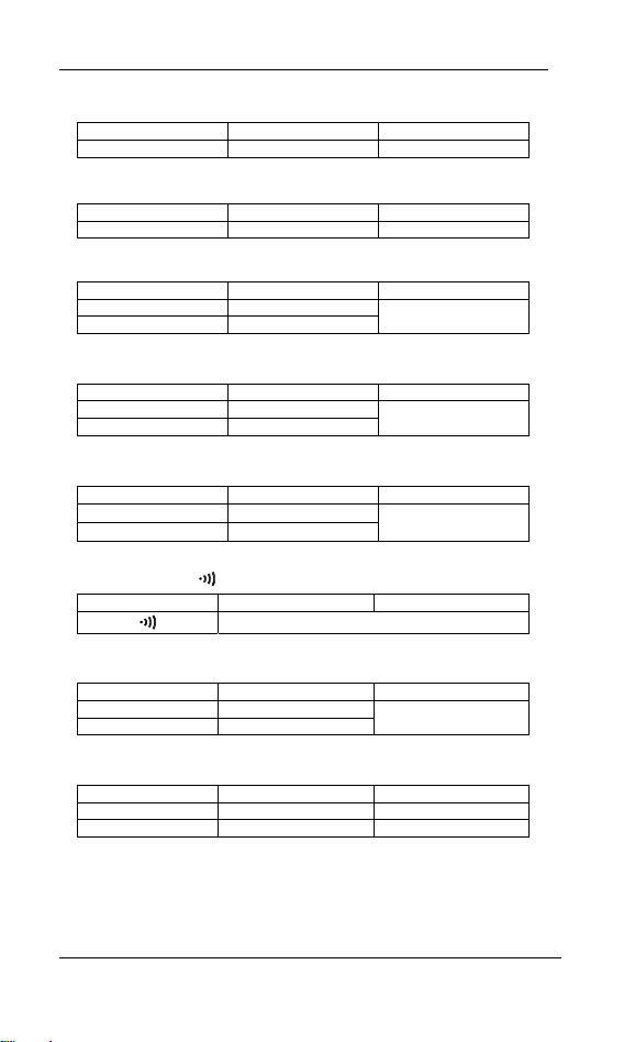
3. ELECTRICAL SPECIFICATION........................................... 2
3-1 DIRECT VOLTAGE..................................................................... 2
3-2 DIRECT VOLTAGE PEAK ........................................................... 2
3-3 ALTERNATING VOLTAGE ........................................................... 2
3-4 ALTERNATING VOLTAGE PEAK................................................... 2
3-5 DIRECT CURRENT ................................................................ 3
3-6 DIRECT CURRENT PEAK ........................................................... 3
3-7 ALTERNATING CURRENT ........................................................... 3
3-8 ALTERNATING CURRENT PEAK .................................................. 3
3-9 RESISTANCE(Ω)....................................................................... 3
3-10 CONTINUITY() .................................................................... 3
3-11 CAPACITANCE........................................................................ 3
3-12 TEMPERATURE(°C/°F ) ........................................................... 3
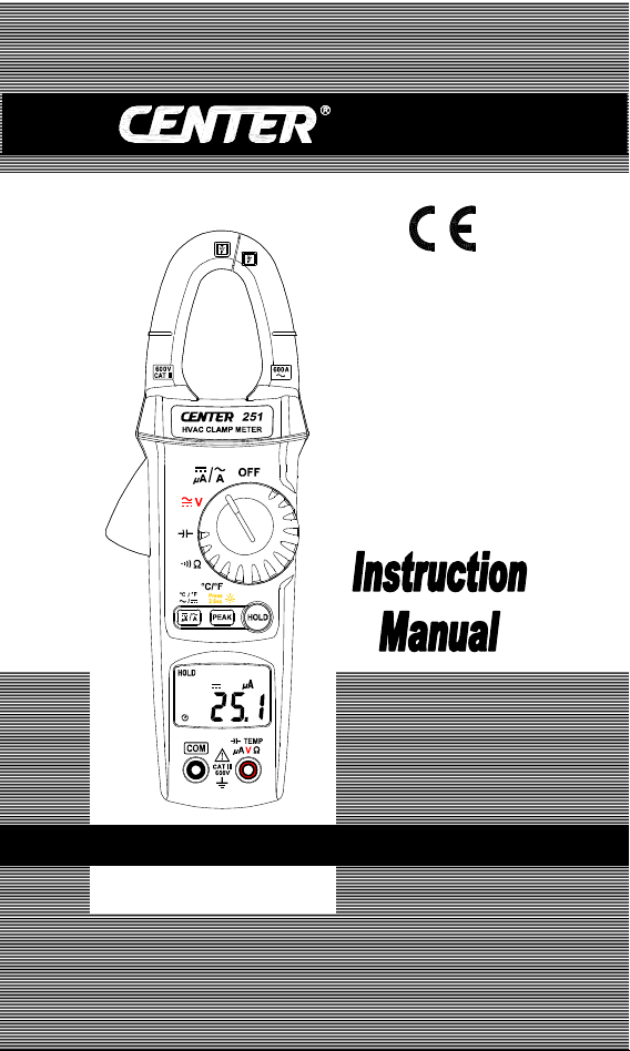
4. DESCRIPTION OF THE INSTRUMENT ............................. 4
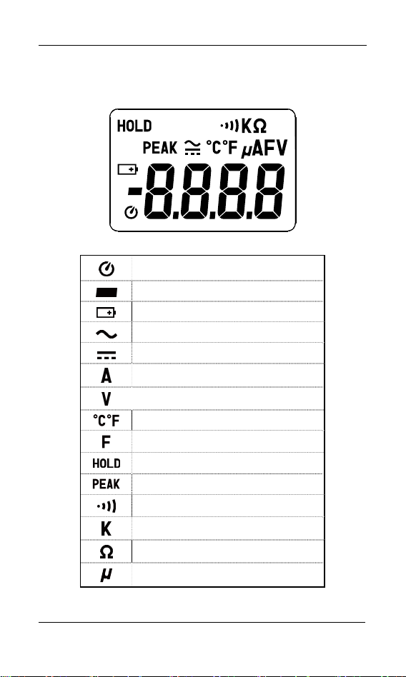
4-1 DESCRIPTION OF THE DISPLAY................................................... 4
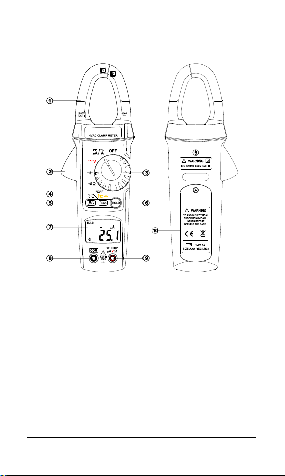
4-2 DESCRIPTION OF FRONT AND REAR ............................................ 5
5. BUTTON INSTRUCTION....................................................... 6
5-1 HOLD FUNCTION .................................................................... 6
5-2 PEAK FUNCTION .................................................................... 6
5-3 BACKLIGHT FUNCTION .......................................................... 6
5-4 DC/AC AND °C/°F FUNCTION ................................................... 6
6. MEASURING INSTRUCTION ............................................... 6
6-1 DC VOLTAGE MEASUREMENT ................................................... 6
6-2 AC VOLTAGE MEASUREMENT.................................................... 7
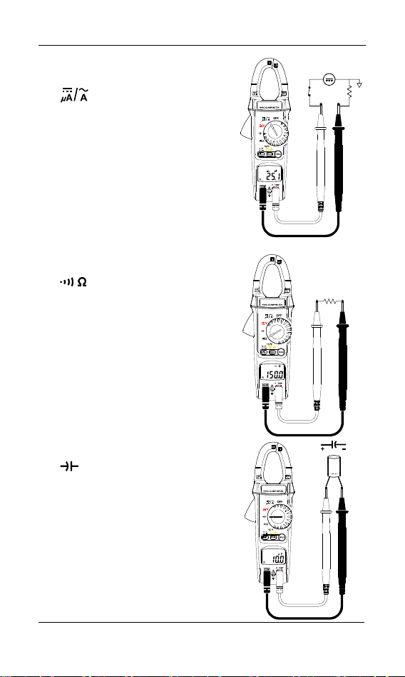
6-3 DC CURRENT MEASUREMENT ...... ....................................... .. .7
6-4 AC CURRENT MEASUREMENT ...................................................8
6-5 RESISTANCE MEASUREMENT .....................................................8
6-6 CAPACITANCE MEASUREMENT ...................................................8
6-7 CONTINUITY MEASUREMENT ......................................................9
6-8 TEMPERATURE MEASUREMENT ..................................................9
7. BATTERY CHANGING ....................................................... .10
8. MAINTENANCE..................................................................... 10

Clamp Meter
1
1. SAFETY INFORMATION
Do not operate the tester if the body of meter or the test lead look
broken.
Check the main function dial and make sure it is at the correct position
before each measurement.
Do not perform resistance and continuity test on a live power system.
Do not apply voltage between the test terminals and test terminal to
ground that exceed the maximum limit record in this manual.
Keep the fingers after the protection ring when measuring through the
test lead.
Chang the battery when the symbol appears to avoid incorrect
data.
Environmental Conditions
Operation Temperature: 0°C to 40°C(32°F to 104°F); < 70 % RH
Storage Temperature: -10°C to 60°C(14°F to 140°F); < 80 % RH
Explanation Symbols
Attention refer to operation Instructions.
Dangerous voltage may be present at terminals.
This instrument has double insulation.
Approvals: EN61010 600V CAT III
2. GENERAL SPECIFICATION
Digital Display:
4 digital liquid crystal (LCD), Maximum reading 6200.
Polarity:
When a negative signal is applied, the signal appears.
Low Battery Indication:
When the battery is under the proper operation range, will appear
on the LCD display.
Sample Rate:
2 times/sec for digital data.

Clamp Meter
2
Power Source:
1.5V size AAA battery X 2
Typical battery Life: 50 hours (without buzzer, backlight function)
Auto Power Off:
If there is no key or dial operation for 30 minutes, the meter will power
itself off to save battery consumption. This function can be disabled by
press and hold the “ HOLD” button then power the unit on.
Over Load:
When the signal larger than the maximum will be show .
Maximum jaw opening:
∅25 mm
Dimensions:
210 x 62 x 36 mm
Weight:
Approx. 273g (with battery)
Accessories:
Carrying case, Batteries, Test Lead & Instruction Manual.
3. ELECTRICAL SPECIFICATION
Accuracy is to within ± [% of the reading + number of counts (dgts)] in
the reference conditions indicated in the appendix.
3-1 Direct Voltage
Range Resolution Accuracy
600 V 0.1 V ±1% + 2dgts
Input impedance: 10 MΩ
3-2 Direct Voltage Peak
Range Resolution Accuracy
600 V 0.1 V ±1.5% + 10dgts
Input impedance: 10 MΩ
3-3 Alternating Voltage
Range Resolution Accuracy
600 V 0.1 V ±1.2% + 8dgts
Input impedance: 10 MΩ
3-4 Alternating Voltage Peak
Range Resolution Accuracy
600 V 0.1 V ±2.0% + 10dgts
Input impedance: 10 MΩ

Clamp Meter
3
3-5 Direct Current
Range Resolution Accuracy
600 μA 0.1μA ±1% + 2dgts
3-6 Direct Current Peak
Range Resolution Accuracy
600μA 0.1μA ±1.5% + 10dgts
3-7 Alternating Current
Range Resolution Accuracy
60 A 0.01 A
600 A 0.1 A ±1.9% + 10dgts
3-8 Alternating Current Peak
Range Resolution Accuracy
60 A 0.1 A
600 A 0.1 A ±2.5% + 10dgts
3-9 Resistance (Ω)
Range Resolution Accuracy
600 Ω0.1 Ω
6.000 KΩ0.001 KΩ±1% + 3dgts
3-10 Continuity
Range Resolution Accuracy
Ohm function Buzzer<40Ω
3-11 Capacitance Measurement
Range Resolution Accuracy
400.0 μF 0.1μF
4000 μF 1 μF ±2.5% + 10dgts
3-12 Temperature Measurement
Range Resolution Accuracy
-50 ~ 600 °C 0.1 °C ±1% + 1.5 °C
-58 ~ 999.8 °F 0.2 °F ±1% + 2.8 °F

Clamp Meter
4
4. DESCRIPTION OF THE INSTRUMENT
4-1 Description Of The Display
Auto power off indication
Polarity indication
Low battery indication
Alternative source indication
Direct source indication
Current measurement indication
Voltage measurement indication
Temperature measurement indication
Capacitance measurement indication
Data hold indication
Peak data indication
Continuity test indication
Measurement unit
Resistance measurement indication
Measurement unit

Clamp Meter
5
4-2 Description Of Front And Rear
○
1Current sensing Clamp
○
2Clamp opening handle
○
3Function select dial
○
4Peak button & Backlight button
○
5AC/DC button & °C/°F button
○
6Data hold button
○
7LCD display
○
8COM input terminal
○
9Positive input termina
○
10 Battery cabinet

Clamp Meter
6
5. BUTTON INSTRUCTION
5-1 HOLD Function
It is possible to freeze the value displayed by pressing on the
"HOLD" button. To deactivate this function, press the "HOLD"
button a second time.
5-2 PEAK Function
If you press on the "PEAK" button , the display will show " "
symbol. When there is a value input that value will be indicated
frozen in the display. If a bigger peak value is input, the peak value
will be updataed and indicated frozen in the display. When you
press on the button again, the function will return to the normal
mode.
5-3 BACKLIGHT Function
If you press and hold the "PEAK" button for 2 seconds or longer, it
will turn on the backlight function.( When you turn on this function, it
will light for 30 seconds).
If you press on the "PEAK" button for 2 seconds or longer again, the
function will be turned off.
5-4 AC/DC or °C/°F Function
When you turn the rotary switch on the voltage/current measurement.
Press the " " button to select ac/dc function.
When you turn the rotary switch on the temperature measurement.
Press the " " button to select °C/°F function.
6. MEASURING INSTRUCTION
6-1 AC Voltage Measurement:
Switch the main function selector
to range.
Connect red test lead to “+"
terminal and black one to the
“COM"terminal.
Measure the voltage by touch the
test lead tips to the test circuit
where the value of voltage is
needed.
Read the result from the LCD
panel.

Clamp Meter
7
600
I
CATI
600V
I
HVACCLAMPMETER
600
A
V
A
ICATI
600V
I
6-2 DC Voltage Measurement:
Switch the main function selector
to range.
Connect red test lead to “+"
terminal and black one to the
“COM"terminal.
Measure the voltage by touch the
test lead tips to the test circuit
where the value of voltage is
needed.
Read the result from the LCD
panel.
6-3 AC Current Measurement:
Switch the main function selector to range.
Open the clamp by pressing the jaw-opening handle and insert the
cable to be measured into the jaw.
Close the clamp and get the reading from the LCD panel.
Note:
Before this measurement, disconnect the test lead with the meter
for safety.
In some occasion that the reading is hard to read, push the HOLD
button and read the result later.
CORRECT
INCORRECT

Clamp Meter
8
6-4 DC Micro Ampere Measurement:
Switch the main function selector to
range.
Connect red test lead to“+"Terminal
and black one to the “COM "
terminal.
Cut the power to the circuit to be
tested and connect the instrument in
series with the circuit with the black
test lead on the negative“-"side
and the red lead on the postive“+"
side being measured.
Apply power and read the ampere
value on LCD.
6-5 Resistance Measurement
Switch the main function selector to
range. Connect red test lead to
“+"terminal and black one to the
“COM"terminal.
Connect tip of the test leads to the
points where the value of the
resistance is needed.
Read the result from the LCD panel.
Note :
When take resistance value from a
circuit system, make sure the power is
cut off and all capacitors need to be
discharged.
6-6 Capacitance Measurement:
Switch the main function selector to
range. Connect red test lead to
“+"terminal and black one to the
“COM"terminal.
Connect tips of the test leads to the
capacitor being tested.
Read the capacitance value on LCD.

Clamp Meter
9
6-7 Continuity Test With Buzzer:
Switch the main function to range.
Connect red test lead to “+"terminal and black one to the
“COM"terminal.
Connect tip of the test leads to the points where the conduction
condition needed.
If the resistance is under 40Ω, the beeper will sound continuously.
Short circuit Open circuit
6-8 Temperature Measurement:
Switch the main function selector to
range.
Connect the K-type temperature probe
to the input jacks noting correct
polarity of the probe.
Press the botten to select °C or °F.
Read the temperature value on the
LCD.

Clamp Meter
10
7. BATTERY CHANGING
When the battery voltage
drop below proper operation
range the symbol will appear
on the LCD display and the
battery needs to be changed.
Before changing the battery,
switch the main dial to
“OFF ”and disconnect test
leads.
Open the back cover by a
screwdriver.
Replace the old batteries with two new 1.5V(AAA Size) battery.
Close the back cover and fasten the screw.
8. MAINTENANCE
WARNING!
Before open the meter, disconnect both test lead and never uses the
meter before the cover is closed.
CAUTION!
To avoid contamination or static damage, do not touch the circuit
board without proper static protection.
8-1 REMARK:
yIf the meter is not going to be used for a long time, take out the
battery and do not store the meter in high temperature or high
humidity environment.
yWhen take current measurement, keep the cable at the center of the
clamp will get more accurate test result.
yRepairs or servicing not covered in this manual should be performed
only by qualified personal.
8-2 CLEANING:
Periodically wipe the case with a dry cloth. Do not use abrasives or
solvents on these instruments.

CENTER TECHNOLOGY CORP.
4 / F NO. 415, Jung-Jeng Rd., 238 Shu-Lin, Taipei, Taiwan
FAX : 886-2-26763925 http : / / www.centertek.com
GCA000251-02000
Table of contents
Other Center Measuring Instrument manuals
Popular Measuring Instrument manuals by other brands

Newport
Newport INF-B Operation manual

HK Instruments
HK Instruments DPT-PRIIMA-MOD Series installation instructions

TTI
TTI TTIDM1000VAR operating instructions

MSA
MSA ALTAIR 2X operating manual

Beckman Coulter
Beckman Coulter AU5800 quick guide

PRECISION DIGITAL
PRECISION DIGITAL ProtEX-RTP PD6830 instruction manual