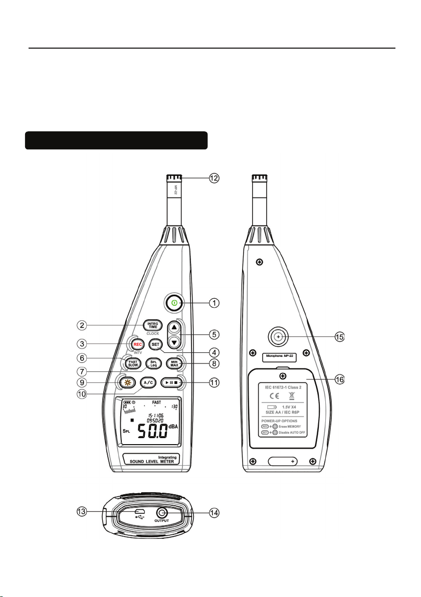
Integrating Sound Level Meter
8
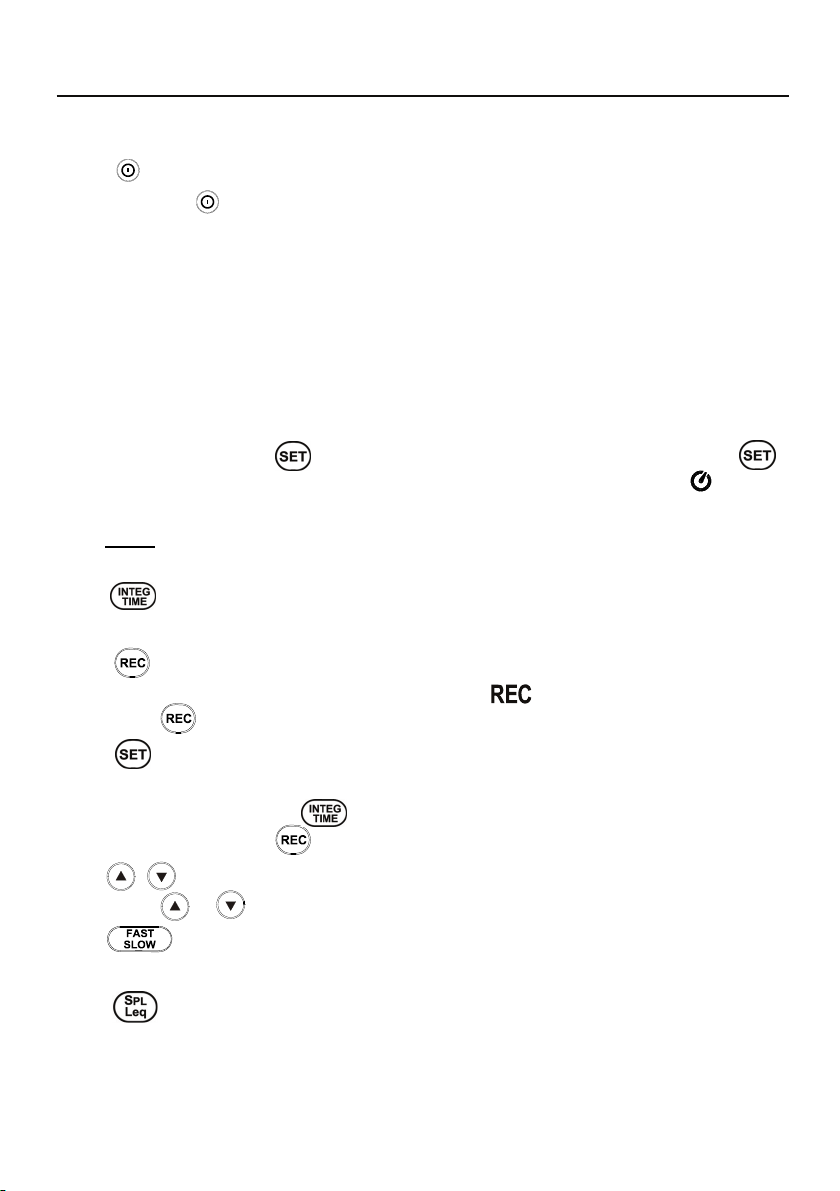
Press button, LCD display will show “ Lo bat ”warning indication. If the
meter is under the record mode, it will stop automatically.
7. Leq & INTEGRATING SETUP
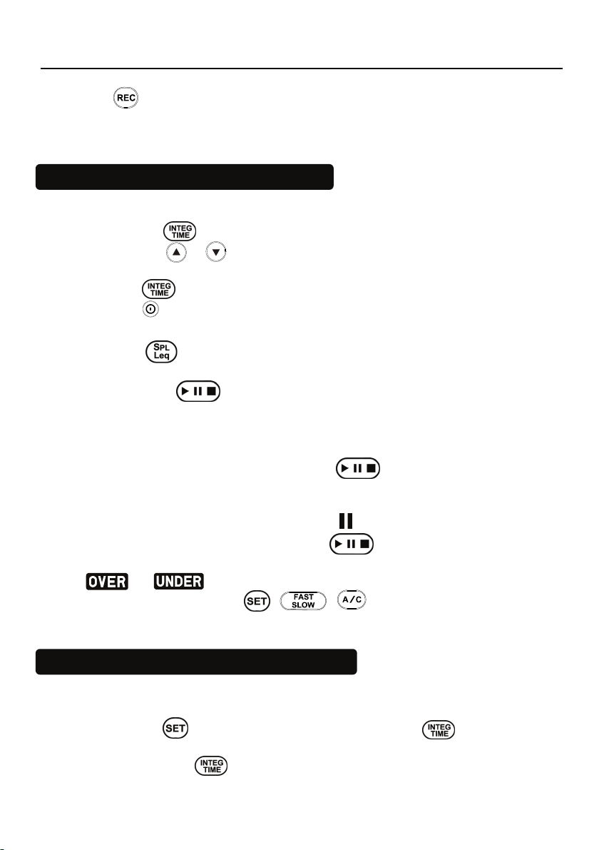
7.1 Setting The Integrating Measurement Time︰
(1) Press the button to enter time setup.
(2) Press the or button to select 10sec, 1min, 5min, 10min, 20min,
30min, 1hr, 2hr, 4hr, 8hr, 16hr, 24hr setting.
(3) Press button again to finish setting.
(4) Press button to exit setting anytime.
7.2 Equivalent Continuous Sound level(Leq) Measurement:
Press the button to select Leq or SPL.
Under Leq measurement, “Leq” symbol is displayed.
(1) Press the button to start, the “ ▶” symbol and the elapsed
measurement time are displayed.
(2) When the Leq measurement time is up, it will automatically terminate
and the “ ■ ” symbol is displayed.
(3) During the Leq measurement, the button can be pressed to
pause, stop or restart. During the pause period, the Leq measuring values
are not evaluated.
(4) During the pause, the pause symbol “ ” is displayed.
(5) To stop the measurement, press the button for 2 seconds.
(6) If an under or over range condition occurs during Leq measurement, the
or symbolwillbekeptonthedisplay.
(7) During this procedure, / / buttons are inoperative.
8. SETTING THE DATE AND TIME
The unit is equiptted with a clock to stamp the measuring date / time.
Date / Time setting Sequence: Year - Month - Day– Hour : Minute : Second
(1) Press the button and then press the CLOCK( ) button to enter
the date and time setting mode.
(2) Press CLOCK( ) button to select year, month, day, hour, minute,
second setup.