Center 265 User manual

Center 265 Leakage Current Clamp Meter
Operating Manual

Center 265 True RMS Leakage Current Clamp Meter
1
TABLE OF CONTENTS
1. SAFETY INFORMATION .................................................................... 1
2. GENERAL SPECIFICATIONS............................................................... 1
3. ELECTRICAL SPECIFICATIONS .......................................................... 2
3-1 AC mA Measurement ....................................................................... 2
3-2 AC AMeasurement .......................................................................... 3
3-3 AC VMeasurement .......................................................................... 3
3-4 DC VMeasurement .......................................................................... 3
3-5 CONTINUITY () .................................................................................. 3
3-6 RESISTANCE(Ω).................................................................................... 3
4. DESCRIPTION OF THE INSTRUMENT.............................................. 4
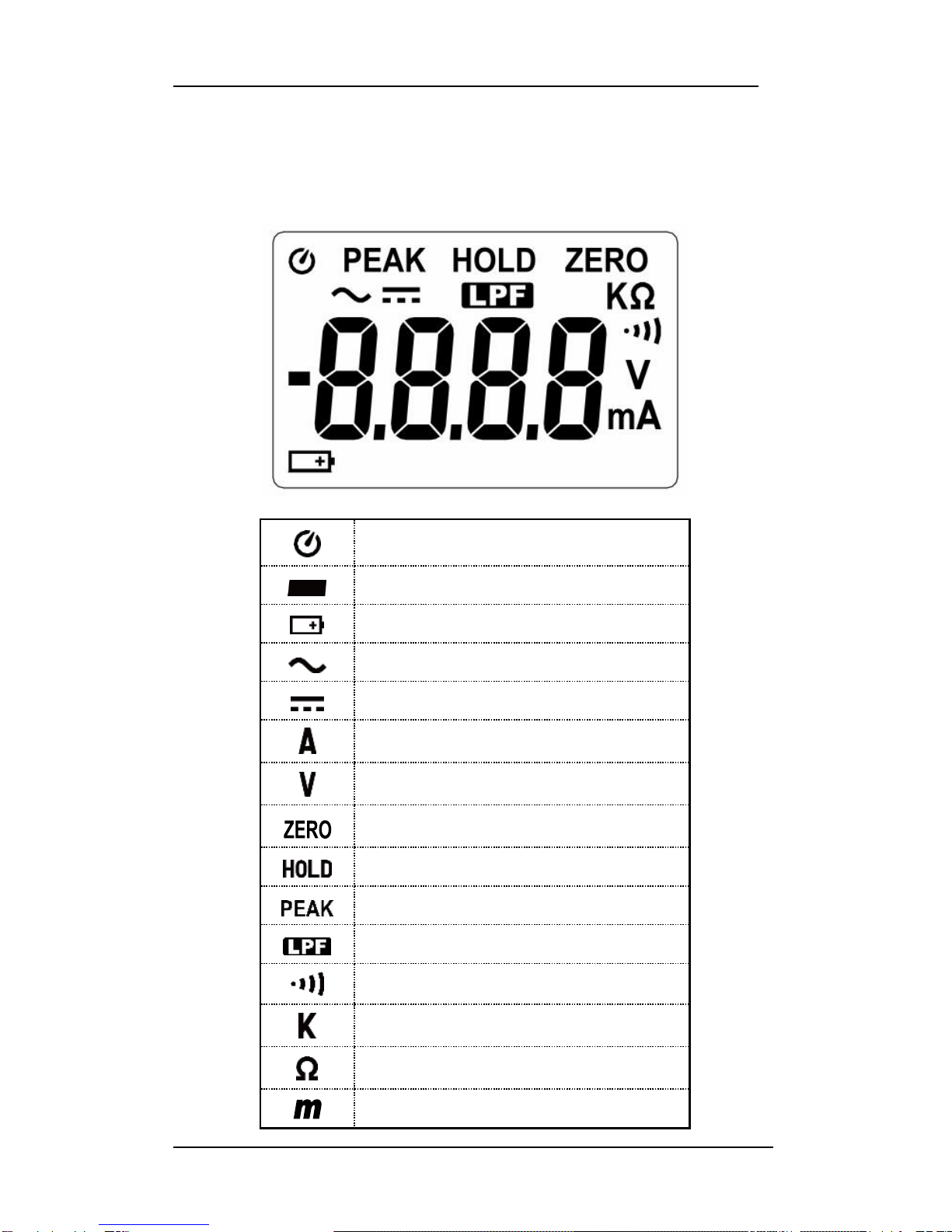
4-1 Description of the display................................................................. 4
4-2 Description of front and rear............................................................ 5
5. BUTTON INSTRUCTION..................................................................... 6
5-1 HOLD &LPF Function........................................................................ 6
5-2 PEAK HOLD Function ........................................................................ 6
5-3 ZERO Function.................................................................................. 6
5-4 BACKLIGHT Function ........................................................................ 6
6. MEASURING INSTRUCTION ............................................................. 7
6-1 AC A&AC mA Measurement ............................................................ 7
6-2 AC VMeasurement .......................................................................... 8
6-3 DC VMeasurement .......................................................................... 9
6-4 Continuity Measurement ................................................................. 9
6-5 Resistance Measurement................................................................10
7. BATTERY CHANGING........................................................................10
8. MAINTENANCE..................................................................................11

Clamp Meter
2
1. SAFETY INFORMATION
1. Do not operate the tester if there is any sign of damage to the
tester or the test leads.
2. Check the main function dial and make sure it is in the correct
position before each measurement.
3. Do not perform resistance and continuity tests on a live power
system.
4. Do not apply voltage between the test terminals and test
terminal to ground that exceed the maximum limits stated in this
manual.
5. Keep your fingers behind the protection ring on the test probes
when using the test leads.
6. Change the battery when the symbol appears to avoid
incorrect data.
Environmental Conditions
Operation Temperature: 0°C to 40°C (32°F to 104°F); < 80 % RH
Storage Temperature: -10°C to 60°C (14°F to 140°F); < 80 % RH
Explanation of Symbols
Attention refer to operating instructions.
Dangerous voltage may be present at the terminals.
This instrument is double insulated.
Approvals: EN61010 300V CAT-IV
2. GENERAL SPECIFICATION
Digital Display:
4 digit liquid crystal (LCD), Maximum reading 6,000 counts.
Polarity:
When a negative signal is applied, the “ ” sign appears.
Low Battery Indication:
When the battery voltage is below that required for proper operation
then the symbol will appear on the LCD display.
Sample Rate:
2 times/sec for digital data.

Center 265 True RMS Leakage Current Clamp Meter
3
Power Source:
1.5V size AAA battery X 2
Typical battery Life: (without buzzer, backlight)
40 hours at AC mA and ACA and ACV function;
60 hours at DCV and Ohm function. (Alkaline battery)
Auto Power Off:
If there is no key or dial operation for 30 minutes, the meter will power
itself off to save battery life. This function can be disabled by pressing
and holding the “HOLD ”button and powering on the unit.
Overload Indication:
When the applied signal is larger than the maximum for the range in
use the display will show .
Maximum Jaw Opening:
23 mm
Dimensions:
206 x 76 x 33.5 mm
Weight:
262g (with battery)
Accessories:
Carrying case, Batteries, Test Leads & Instruction Manual.
3. ELECTRICAL SPECIFICATION
The accuracy specification is defined as ± ( percentage of reading +
number of counts ) At 23±5°C, ≦80 %RH.
3-1 ACmA (True RMS)
Range
Resolution
Accuracy
50~60 Hz
50~500 Hz
6.000 mA
0.001 mA
1.0% + 8 counts
2.0% + 8 counts
60.00 mA
0.01 mA
1.0% + 5 counts
2.0% + 5 counts
600.0 mA
0.1 mA
Zero correction: Fractions smaller than approximately 0.006 mA are
calibrated to zero.
Low Pass Filter
Range
Resolution
Accuracy
6.000 mA
0.00 1mA
2.0% + 8 counts
60.00 mA
0.01 mA
2.0% + 5 counts
600.0 mA
0.1 mA

Clamp Meter
4
3-2 ACA (True RMS)
Range
Resolution
Accuracy
50~60 Hz
50~500 Hz
6.000 A
0.001 A
1.0% + 5 counts
2.0% + 5 counts
60.00 A
0.01 A
Low Pass Filter
Range
Resolution
Accuracy
6.000 A
0.001 A
2.0% + 5 counts
60.00 A
0.01 A
3-3 ACV (True RMS)
Range
Resolution
Accuracy
50~500 Hz
60.00 V
0.01 V
1.0% + 3 counts
300.V
0.1 V
Input impedance: 1 M
3-4 DCV
Range
Resolution
Accuracy
60.00 V
0.01 V
1.0% + 2 counts
300.0 V
0.1 V
Input impedance: 1 M
3-5 Continuity
Range
Buzzer Function
Ohm < 45
3-6 Resistance ()
Range
Resolution
Accuracy
600.0
0.1
1.0% + 2 counts
6.000 k
0.001 k
60.00 k
0.01 k
600.0 k
0.1 k

Center 265 True RMS Leakage Current Clamp Meter
5
4.DESCRIPTION OF THE INSTRUMENT
4-1 Description of the Display
Auto power off indication
Polarity indication
Low battery indication
AC measurement indication
DC measurement indication
Current measurement indication
Voltage measurement indication
ZERO indication
Data hold indication
PEAK hold indication
Low pass filter indication
Continuity test indication
Measurement unit
Resistance measurement indication
Measurement unit

Clamp Meter
6
4-2 Description Of Front And Rear
○
1Current Sensing Clamp
○
2Safety protection ring
○
3Backlight button
○
4Clamp opening handle
○
5Function select dial
○
6ZERO button
○
7PEAK & / button
○
8Data hold & LPF button
○
9LCD display
○
10 COM input terminal
○
11 Positive input terminal
○
12 Battery compartment

Center 265 True RMS Leakage Current Clamp Meter
7
5. BUTTON INSTRUCTION
5-1 HOLD & LPF Function
It is possible to freeze the displayed value by pressing on the "HOLD"
button. Press the "HOLD" button again to exit the Hold mode.
To activate the Low Pass Filter (LPF) feature, press and hold the
“LPF” button until the symbol displays. To deactivate the LPF feature,
press and hold the “LPF” button for 2 seconds. The meter will return
to normal mode of operation.
The Cut-Off frequency of the low pass filter is about 160 Hz with
attenuation characteristic of approx. -24 dB/octave.
Note: The LPF function operates on the AC A and AC mA ranges.
5-2 PEAK Hold & / Function Selection
Press "PEAK" button to enter the PEAK mode, the meter records the
peak maximum value. Press the " PEAK " button again, to exit the
peak mode.
When you turn the rotary switch to the Ohms / Continuity Test
position, press the "PEAK" button to select Resistance measurement,
press the "PEAK" button again to select continuity test with buzzer.
5-3 ZERO Function
Press "ZERO" button to enter the Zero mode, ZERO Annunciate will
appear and Zero the display. The reading is stored as reference
value for subsequent measurement.
Press the " ZERO " button again, to exit the zero mode.
5-4 BACKLIGHT Function
When the " " button is pressed, the backlight will be turned on.
Press the button again to turn the backlight off. If the button is not
pressed again then the backlight will be automatically turned off in
about 30 seconds after it is turned on.

Clamp Meter
8
6. MEASURING INSTRUCTION
6-1 AC A and AC mA measurement:
1. Set the range selector switch to the desired position. The
current to be measured should be within the selected measuring
range.
2. Normal measurement (see Fig.1):
Press the jaw trigger to open the clampmeter jaws and close them
over one conductor only. The measured current value is shown on the
display. Earth leakage current or any small AC current that flows
through a ground wire can also be measured by this method.
3. Measuring out of balance leakage current (see Fig.2):
Clamp onto all conductors except the ground wire. The measured
imbalance current value is shown on the display.
Before this measurement, disconnect any test leads from the meter
for safety.
In some cases wherein reading the display is difficult, press the HOLD
button and read the result after the clamp is removed from the
conductors.
Fig.1 Normal measurement:
INCORRECT CORRECT

Center 265 True RMS Leakage Current Clamp Meter
9
Fig.2 Measuring out of balance leakage current:
3-Phase 3-Wire system Single-Phase 2-Wire system
6-2 AC V Measurement:
WARNING!
Maximum Input Voltage is 300V AC/DC. Do not attempt to
Take any voltage measurement that may exceed this
maximum to avoid Electrical shock hazard and/or damage to
this instrument.
Switch the main function selector
to range.
Connect the red test lead to
the "+ ”terminal and the black
lead to the “COM”terminal.
Measure the voltage by touching
the test lead tips to the test circuit
where the voltage measurement is
required.
Read the result from the LCD
display.

Clamp Meter
10
6-3 DC V Measurement:
Switch the main function
selector to range.
Connect the red test lead to
the“+”terminal and black
lead to the “COM”terminal.
Measure the voltage by
touching the test lead tips to
the test circuit where the
value of voltage is needed.
Read the result from the LCD.
6-4 Continuity Test With Buzzer:
Switch the main function to range.
Connect the red test lead to the “+”terminal and the black lead to
the “COM”terminal.
Connect tip of the test leads to the points between which continuity is
to be measured.
If the resistance is under 45Ω, the beeper will sound continuously.
Short circuit Open circuit

Center 265 True RMS Leakage Current Clamp Meter
11
6-5 Resistance Measurement
Switch the main function to
range.
Connect the red test lead to the
“+”terminal and the black lead
to the "COM" terminal.
Connect tip of the test leads to the
points where the value of the
resistance is to be measured.
Read the result from the LCD.
Note:
When measuring resistance in a
circuit, make sure any power on
the circuit is turned off and any
capacitors are discharged.
7. CHANGING THE BATTERY
When the battery voltage drops below that required for proper
operation of the instrument, the battery symbol will appear on the
LCD display and the battery should be changed.
Before changing the battery, switch the main dial to “OFF ”and
disconnect test leads.
Open the back cover using a screwdriver.
Replace the old batteries with two new 1.5V (AAA Size) batteries.
Close the back cover and tighten the screw before using the meter.

Clamp Meter
12
8. MAINTENANCE
WARNING!
Before opening the meter, disconnect both test leads. Never use the
meter unless the battery cover is in place and the screw is tightened.
CAUTION!
To avoid contamination or static damage, do not touch the circuit
board without proper static protection.
8-1 REMARKS:
If the meter is not going to be used for a long time then please
remove the battery and do not store the meter in a high temperature
or high humidity environment.
Keep the cable in the center of the clamp will return a more accurate
test result when making current measurements.
Repairs or servicing not covered in this manual should only be
performed by qualified personnel.
8-2 CLEANING:
Periodically wipe the case with a dry cloth. Do not use abrasives or
solvents on these instruments.
Distributed By :
TRIO Test & Measurement Pty Ltd
T. 1300 853 407
F. 1300 853 409
http://www.triotest.com.au
Table of contents
Other Center Measuring Instrument manuals
Popular Measuring Instrument manuals by other brands

Hydac
Hydac SMU 1000 operating manual

EyeQue
EyeQue VisionCheck EQ102 product manual

MTS Systems
MTS Systems Level Plus STI Installation & operation manual

Dwyer Instruments
Dwyer Instruments DPMF Series Installation and operating instructions

ABB
ABB SM500F Instruction

Newcon Optik
Newcon Optik LRB 20000 Operation manual