77
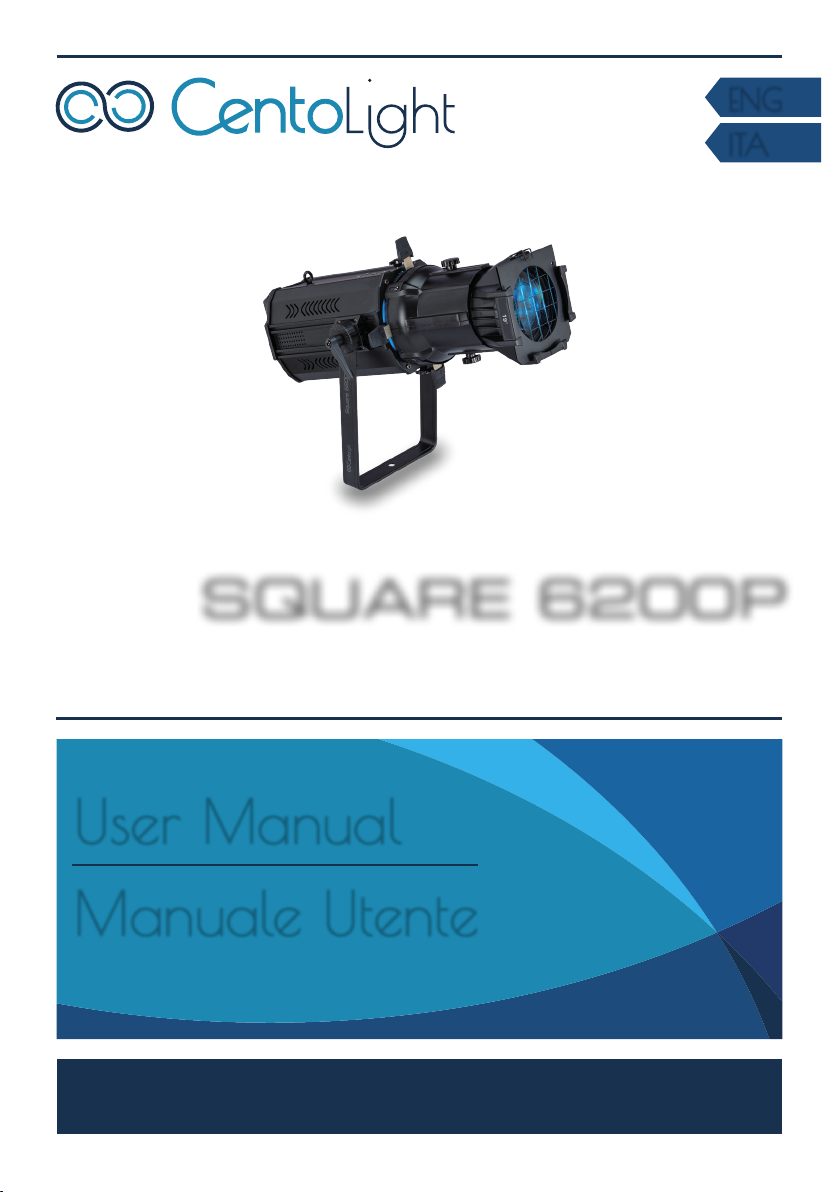
SQUARE 6200P User Manual
Eng
yThe unit can not be used near water; for example near a bathtub, a kitchen sink,
a swimming pool, etc.
3.3. Heat
yDo not use in a confined space. Always install the product in a location with
adequate ventilation, at least 20in (50 cm) from adjacent surfaces. Be sure that
no ventilation slots on the product’s housing are blocked.
yThe apparatus should be located away from heat sources such as radiators,
stoves or other appliances that produce heat.
Don not use it when maximum ambient temperature is higher than 50°C. Work
temperature ranges from -20°C to 55°C (-4°F to 131°F).
3.4.Servicing
yDo not implement any servicing other than those means described in the man-
ual. Refer all servicing to qualified service personnel only. The internal compo-
nents of the equipment must be purchased from the manufacturer. Only use
accessories/attachments or parts recommended by the manufacturer.
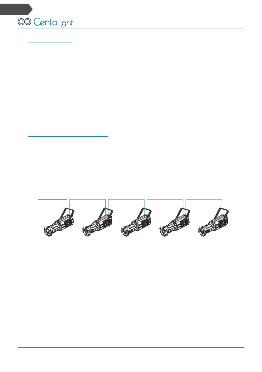
4 - inTroduCTion
Centolight SQUARE 6200P is a professional LED Profile with 26° beam (also avail-
able optional 19° lens tube) designed for installations in which high LED reliability
and a wide range of colors are required.
The light source is a 200W LED RGBALC (Red, Green, Blue, Lime, Amber, Cyan) 6in1
with CRI ≥90 and color temperature between 2000K and 8500K. The combination
of these six basic colors allows a countless infinite palette, and lets you to recreate
even pastel and white colors at different temperatures able to satisfy even the most
demanding professionals.
The SQUARE 6200P is designed for indoor applications ranging from TV studios, live
entertainment, theaters and museums. Great attention is paid to quality of dimmer
control and chip temperature, to minimize the consequences of using LEDs instead
of traditional lamps.
The cooling system uses high precision fans in order to keep noise within 25dB @
1m. The 4 beam-shaping shutter system allows both radial and angled adjustment
of the beam. The fixture is equipped with a compartment for gobos and manual iris
(both optional), as well as the front color-frame holder (included).