Central Pneumatic 93458 Assembly instructions

Visit our website at: http://www.harborfreight.com
Owner’s Manual & Safety Instructions
Save This Manual Keep this manual for the safety warnings and precautions, assembly,
operating, inspection, maintenance and cleaning procedures. Write the product’s serial number in the
back of the manual near the assembly diagram (or month and year of purchase if product has no number).
Keep this manual and the receipt in a safe and dry place for future reference. 18e
When unpacking, make sure that the product is intact
and undamaged. If any parts are missing or broken,
please call 1-888-866-5797 as soon as possible.
Copyright©2005 by Harbor Freight Tools®. All rights reserved.
No portion of this manual or any artwork contained herein may be reproduced in
any shape or form without the express written consent of Harbor Freight Tools.
Diagrams within this manual may not be drawn proportionally. Due to continuing
improvements, actual product may differ slightly from the product described herein.
Tools required for assembly and service may not be included.
Read this material before using this product.
Failure to do so can result in serious injury.
SAVE THIS MANUAL.

Page 2 For technical questions, please call 1-888-866-5797. Item 93458
Table of Contents
Safety ......................................................... 2
Specifications ............................................. 6
Setup .......................................................... 7
Operation................................................... 10
Maintenance.............................................. 12
Parts List and Diagram.............................. 14
Warranty .................................................... 16
WARNING SYMBOLS AND DEFINITIONS
This is the safety alert symbol. It is used to alert you to potential personal injury hazards.
Obey all safety messages that follow this symbol to avoid possible injury or death.
Indicates a hazardous situation which, if not avoided,
will result in death or serious injury.
Indicates a hazardous situation which, if not avoided,
could result in death or serious injury.
Indicates a hazardous situation which, if not avoided,
could result in minor or moderate injury.
Addresses practices not related to personal injury.
IMPORTANT SAFETY INSTRUCTIONS
INSTRUCTIONS PERTAINING TO A RISK OF FIRE,
ELECTRIC SHOCK, OR INJURY TO PERSONS
WARNING – When using tools, basic precautions should always be followed, including the following:
General
To reduce the risks of electric shock,
fire, and injury to persons, read all the
instructions before using the tool.
Work Area
1. Keep the work area clean and well lighted.
Cluttered benches and dark areas increase the
risks of electric shock, fire, and injury to persons.
2. Do not operate the tool in explosive
atmospheres, such as in the presence
of flammable liquids, gases, or dust.
The tool is able to create sparks resulting
in the ignition of the dust or fumes.
3. Keep bystanders, children, and visitors away
while operating the tool. Distractions are
able to result in the loss of control of the tool.
SAFETY OPERATION MAINTENANCESETUP

Page 3For technical questions, please call 1-888-866-5797.Item 93458
Personal Safety
1. Stay alert. Watch what you are doing and
use common sense when operating the tool.
Do not use the tool while tired or under the
influence of drugs, alcohol, or medication.
A moment of inattention while operating the
tool increases the risk of injury to persons.
2. Dress properly. Do not wear loose
clothing or jewelry. Contain long hair.
Keep hair, clothing, and gloves away from
moving parts. Loose clothes, jewelry, or long
hair increases the risk of injury to persons as
a result of being caught in moving parts.
3. Avoid unintentional starting. Be sure the switch
is off before connecting to the air supply.
Do not carry the tool with your finger on the switch or
connect the tool to the air supply with the switch on.
4. Do not overreach.
Keep proper footing and balance at all times.
Proper footing and balance enables better
control of the tool in unexpected situations.
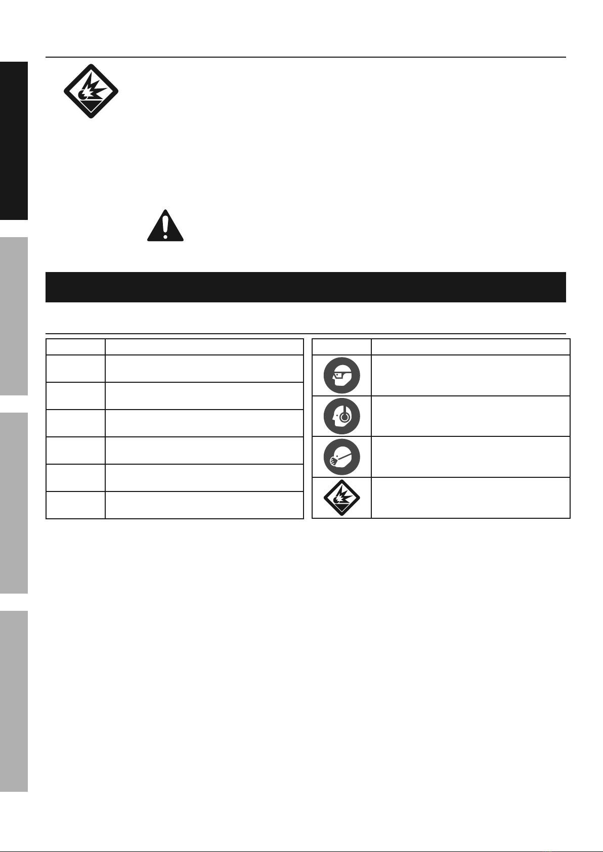
5. Use safety equipment.
A dust mask, non-skid safety shoes
and a hard hat must be used for the
applicable conditions.
6. Always wear eye protection.
Wear ANSI-approved safety goggles.
7. Always wear hearing protection
when using the tool.
Prolonged exposure to high intensity
noise is able to cause hearing loss.
Tool Use and Care
1. Use clamps or another practical way to secure
and support the workpiece to a stable platform.
Holding the work by hand or against the body is
unstable and is able to lead to loss of control.
2. Do not force the tool. Use the correct tool for the
application. The correct tool will do the job better
and safer at the rate for which the tool is designed.
3. Do not use the tool if the switch does
not turn the tool on or off. Any tool that
cannot be controlled with the switch is
dangerous and must be repaired.
4. Disconnect the tool from the air source before
making any adjustments, changing accessories,
or storing the tool. Such preventive safety
measures reduce the risk of starting the tool
unintentionally. Turn off and detach the air supply,
safely discharge any residual air pressure, and
release the trigger before leaving the work area.
5. Store the tool when it is idle out of reach
of children and other untrained persons.
A tool is dangerous in the hands of untrained users.
6. Maintain the tool with care.
A properly maintained tool reduces the
risk of binding and is easier to control.
7. Check for misalignment or binding of moving
parts, breakage of parts, and any other condition
that affects the tool's operation. If damaged,
have the tool serviced before using. Many accidents
are caused by poorly maintained tools.
There is a risk of bursting if the tool is damaged.
8. Use only accessories that are identified by the
manufacturer for the specific tool model. Use of
an accessory not intended for use with the specific
tool model, increases the risk of injury to persons.
Service
1. Tool service must be performed only
by qualified repair personnel.
2. When servicing a tool, use only identical
replacement parts. Use only authorized parts.
3. Use only the lubricants supplied with the
tool or specified by the manufacturer.
SAFETYOPERATIONMAINTENANCE SETUP

Page 4 For technical questions, please call 1-888-866-5797. Item 93458
Air Source
1. Never connect to an air source that
is capable of exceeding 200 psi.
Over pressurizing the tool may cause
bursting, abnormal operation, breakage
of the tool or serious injury to persons.
Use only clean, dry, regulated compressed air at the
rated pressure or within the rated pressure range as
marked on the tool. Always verify prior to using the
tool that the air source has been adjusted to the
rated air pressure or within the rated air-pressure
range.
2. Never use oxygen, carbon dioxide, combustible
gases or any bottled gas as an air source
for the tool. Such gases are capable of
explosion and serious injury to persons.
SAVE THESE INSTRUCTIONS.
Symbols and Specific Safety Instructions
Symbol Definitions
Symbol Property or statement
PSI Pounds per square inch of pressure
BPM Blows per minute
CFM Cubic Feet per Minute flow
SCFM Cubic Feet per Minute flow
at standard conditions
NPT National pipe thread, tapered
NPS National pipe thread, straight
Symbol Property or statement
WARNING marking
concerning Risk of Eye Injury.
Wear ANSI-approved eye protection.
WARNING marking concerning Risk of
Hearing Loss. Wear hearing protection.
WARNING marking concerning
Risk of Respiratory Injury. Wear
NIOSH-approved dust mask/respirator.
WARNING marking concerning
Risk of Explosion.
SAFETY OPERATION MAINTENANCESETUP

Page 5For technical questions, please call 1-888-866-5797.Item 93458
Specific Safety Instructions
1. Attach the Safety Cap to the Riveter before use.
Turn the slot in the Safety Cap upward
to avoid spilling used Rivet Pins.
2. The warnings and precautions discussed in this
manual cannot cover all possible conditions and
situations that may occur. It must be understood
by the operator that common sense and caution
are factors which cannot be built into this
product, but must be supplied by the operator.
3. Obey the manual for the air compressor
used to power this tool.
4. Install an in-line shutoff valve to allow
immediate control over the air supply in an
emergency, even if a hose is ruptured.
5. Do not lay the tool down until it has come to
a complete stop. Moving parts can grab the
surface and pull the tool out of your control.
Vibration Precautions
This tool vibrates during use. Repeated or
long-term exposure to vibration may cause
temporary or permanent physical injury,
particularly to the hands, arms and shoulders. To
reduce the risk of vibration-related injury:
1. Anyone using vibrating tools regularly or for
an extended period should first be examined
by a doctor and then have regular medical
check-ups to ensure medical problems are not
being caused or worsened from use. Pregnant
women or people who have impaired blood
circulation to the hand, past hand injuries,
nervous system disorders, diabetes, or Raynaud's
Disease should not use this tool. If you feel
any symptoms related to vibration (such as
tingling, numbness, and white or blue fingers),
seek medical advice as soon as possible.
2. Do not smoke during use. Nicotine reduces
the blood supply to the hands and fingers,
increasing the risk of vibration-related injury.
3. Wear suitable gloves to reduce the
vibration effects on the user.
4. Use tools with the lowest vibration
when there is a choice.
5. Include vibration-free periods each day of work.
6. Grip tool as lightly as possible (while still keeping
safe control of it). Let the tool do the work.
7. To reduce vibration, maintain
tool as explained in this manual.
If abnormal vibration occurs, stop immediately.
SAVE THESE INSTRUCTIONS.
SAFETYOPERATIONMAINTENANCE SETUP

Page 6 For technical questions, please call 1-888-866-5797. Item 93458
Functional Description
Specifications
Maximum Air Pressure 90 PSI
Air Inlet 1/4″ -18 NPT
Average Air Consumption 3 CFM @ 90 PSI
Rivet Pin Capacity 3/32″, 1/8″, 5/32″, 3/16″
(Nosepiece change needed)
Maximum Pull Force 2,800 lb.
Components and Controls
Nosepiece
(1A, 1B, 1C, 1D)
Head (11)
Pin Cap (23)
Trigger (40)
Pin Cap
Nut (22)
Quick Connector (53)
SAFETY OPERATION MAINTENANCESETUP

Page 7For technical questions, please call 1-888-866-5797.Item 93458
Initial Tool Set Up/Assembly
Read the ENTIRE IMPORTANT SAFETY INFORMATION section at the beginning of this
manual including all text under subheadings therein before set up or use of this product.
Note: For additional information regarding the parts listed in the following pages,
refer to the Assembly Diagram near the end of this manual.
Note: This air tool may be shipped with a protective plug covering the air inlet. Remove this plug before set up.
Air Supply
TO PREVENT SERIOUS INJURY FROM EXPLOSION:
Use only clean, dry, regulated, compressed air to power this tool.
Do not use oxygen, carbon dioxide, combustible gases,
or any other bottled gas as a power source for this tool.
1. Incorporate a filter, regulator with pressure
gauge, in-line shutoff valve, and quick coupler
for best service, as shown on Figure A on
page 8 and Figure B on page 9.
An in-line shutoff ball valve is an important
safety device because it controls the air
supply even if the air hose is ruptured.
The shutoff valve should be a ball valve
because it can be closed quickly.
2. Attach an air hose to the compressor's air outlet.
Connect the air hose to the air inlet of the tool.
Other components, such as a coupler plug
and quick coupler, will make operation
more efficient, but are not required.
WARNING! TO PREVENT SERIOUS INJURY
FROM ACCIDENTAL OPERATION:
Do not install a female quick coupler on the tool.
Such a coupler contains an air valve that will
allow the air tool to retain pressure and operate
accidentally after the air supply is disconnected.
Note: Air flow, and therefore tool performance,
can be hindered by undersized air supply components.
The air hose must be long enough to reach
the work area with enough extra length to
allow free movement while working.
3. Release the tool's trigger.
4. Close the in-line shutoff valve between
the compressor and the tool.
5. Turn on the air compressor according to
the manufacturer's directions and allow it
to build up pressure until it cycles off.
6. Adjust the air compressor's output regulator
so that the air output is enough to properly
power the tool, but the output will not exceed
the tool's maximum air pressure at any time.
Adjust the pressure gradually, while checking the
air output gauge to set the right pressure range.
7. Inspect the air connections for leaks.
Repair any leaks found.
8. If the tool will not be used at this time, turn off
and detach the air supply, safely discharge
any residual air pressure, and release the
trigger to prevent accidental operation.
Note: Residual air pressure should not be present
after the tool is disconnected from the air supply.
However, it is a good safety measure to attempt to
discharge the tool in a safe fashion after disconnecting
to ensure that the tool is disconnected and not powered.
SAFETYOPERATIONMAINTENANCE SETUP

Page 8 For technical questions, please call 1-888-866-5797. Item 93458
Figure A: Portable Air Supply Setup
G
A
E
E
H
F
B
Non-lubricated
Tools
Lubricated
Tools
A
B
C
C
DA
Description Function
A Air Hose Connects air to tool
B Filter Prevents dirt and condensation from damaging tool or workpiece
C Regulator Adjusts air pressure to tool
D Lubricator (optional) For air tool lubrication
E Coupler and Plug Provides quick connection and release
F Leader Hose (optional) Increases coupler life
G Air Cleaner / Dryer (optional) Prevents water vapor from damaging workpiece
H Air Adjusting Valve (optional) For fine tuning airflow at tool
SAFETY OPERATION MAINTENANCESETUP

Page 9For technical questions, please call 1-888-866-5797.Item 93458
Figure B: Stationary Air Supply Setup
N
L
L O
M
C
C
Non-lubricated Tools
Lubricated
Tools
H
I
I
J
JKH
F
G
E
Slope
F
F
B
B
A
A
CD
Description Function
A Vibration Pads For noise and vibration reduction
B Anchor Bolts Secures air compressor in place
C Ball Valve Isolates sections of system for maintenance
D Isolation Hose For vibration reduction
EMain Air Line - 3/4″ minimum recommended Distributes air to branch lines
F Ball Valve To drain moisture from system
GBranch Air Line -1/2″ minimum recommended Brings air to point of use
H Air Hose Connects air to tool
I Filter Prevents dirt and condensation from damaging tool or workpiece
J Regulator Adjusts air pressure to tool
K Lubricator (optional) For air tool lubrication
L Coupler and Plug Provides quick connection and release
M Leader Hose (optional) Increases coupler life
N Air Cleaner / Dryer (optional) Prevents water vapor from damaging workpiece
O Air Adjusting Valve (optional) For fine tuning airflow at tool
SAFETYOPERATIONMAINTENANCE SETUP

Page 10 For technical questions, please call 1-888-866-5797. Item 93458
Operating Instructions
Read the ENTIRE IMPORTANT SAFETY INFORMATION section at the beginning of this
manual including all text under subheadings therein before set up or use of this product.
Inspect tool before use, looking for damaged, loose, and missing parts.
If any problems are found, do not use tool until repaired.
Tool Set Up
TO PREVENT SERIOUS INJURY FROM ACCIDENTAL OPERATION:
Turn off the tool, detach the air supply, safely discharge any residual air pressure in the tool, and
release the trigger before performing any inspection, maintenance, or cleaning procedures.
TO PREVENT SERIOUS INJURY:
Do not adjust or tamper with any control or component in a way not specifically explained within
this manual. Improper adjustment can result in tool failure or other serious hazards.
Priming:
1. Use the Wrench (36) to unscrew and remove the
Cylinder Cap (33) from the bottom of the Riveter.
2. Use a pair of pliers (not included) to remove the
Piston Assembly (30-33) from the Air Cylinder (29).
3. Hold the Air Cylinder (29) upside down, and pour
in hydraulic fluid (not included). The fill level
should only reach the top of the Housing (15).
4. Insert the Piston Assembly (30-33)
back into the Air Cylinder (29).
5. Use the Wrench (36) to firmly screw the
Cylinder Cap (33) back onto the Air Cylinder (29).
Wrench
(36)
Air Cylinder
(29)
Air Cylinder
(29)
Air Piston
Lock Nut (30-3)
Piston Asm.
(30-33)
Cylinder
Cap (33)
Figure C: Priming the Cylinder
Nosepieces:
1. The Riveter comes with four Nosepieces:
(1A = 3/16″), (1B = 5/32″), (1C = 1/8″), (1D = 3/32″).
2. Use the Wrench (36) to remove the
old nosepiece and install the new one.
Tighten the new nosepiece in place before use.
SAFETY OPERATION MAINTENANCESETUP

Page 11For technical questions, please call 1-888-866-5797.Item 93458
Workpiece and Work Area Set Up
1. Designate a work area that is clean and well-lit.
The work area must not allow access by children
or pets to prevent distraction and injury.
2. Route the air hose along a safe route to reach
the work area without creating a tripping hazard
or exposing the air hose to possible damage.
The air hose must be long enough to reach
the work area with enough extra length to
allow free movement while working.
3. Secure loose workpieces using a vise or clamps
(not included) to prevent movement while working.
4. There must not be hazardous objects
(such as utility lines or foreign objects) nearby
that will present a hazard while working.
General Operating Instructions
1. Secure the Pin Cap (23) firmly to the
Riveter by tightening the Pin Cap Nut (22).
While securing turn the slot in the Pin Cap
upward to avoid spilling used rivet pins.
2. Depending on the size of rivet’s pin used,
attach the corresponding Nosepiece size
(3/16″, 5/32″, 1/8″, or 3/32″) with the Wrench (36).
IMPORTANT: When drilling rivet holes in a workpiece,
use the same diameter drill bit as the
outer diameter of rivet you will be using.
WARNING! Verify that work surface has
no hidden utility lines before drilling.
3. Attach an air hose to the
Quick Connector (53) of the Riveter.
4. Turn on the air compressor, and set its regulator to
the needed pressure. Do not exceed the tool’s
maximum air pressure rating.
5. Insert the small end of a rivet fully through
the Nosepiece (1A, 1B, 1C, or 1D).
CAUTION! Keep clear of the trigger
when inserting rivets.
6. Insert the rivet through the predrilled
hole in the workpiece.
7. Hold the Riveter firmly with both hands, and squeeze
the Trigger (40) to activate the Riveter. Repeat as
necessary. Then, release pressure on the Trigger.
8. Check to be sure the rivet looks soild and
securely locks the workpiece together.
• If the installed rivet is too loose then the
workpiece sections will move and not be locked
together. This indicates the rivet pin was not
adequately pulled through the workpiece. Either
the wrong size rivet was used or Riveter’s Jaw
Case is too loose and not gripping the rivet pin
well enough to pull it fully through the workpiece.
• A concave, deformed or broken rivet head
indicates the rivet pin was pulled too far into
the workpiece. Either the wrong size rivet was
used or Riveter’s Jaw Case is too tight and not
properly releasing the rivet pin during installation.
9. If the tool requires more force to accomplish
the task, verify that the tool receives sufficient,
unobstructed airflow (CFM) and increase the
pressure (PSI) output of the regulator up to the
maximum air pressure rating of this tool.
CAUTION! TO PREVENT INJURY FROM
TOOL OR ACCESSORY FAILURE:
Do not exceed the tool's
maximum air pressure rating.
If the tool still does not have sufficient force
at maximum pressure and sufficient airflow,
then a larger tool may be required.
10. To prevent accidents, turn off the tool, detach the air
supply, safely discharge any residual air pressure
in the tool, and release the trigger after use.
Clean external surfaces of the tool with clean,
dry cloth, and apply a thin coat of tool oil.
Then store the tool indoors out of children's reach.
SAFETYOPERATIONMAINTENANCE SETUP

Page 12 For technical questions, please call 1-888-866-5797. Item 93458
User-Maintenance Instructions
Procedures not specifically explained in this manual must
be performed only by a qualified technician.
TO PREVENT SERIOUS INJURY FROM ACCIDENTAL OPERATION:
Turn off the tool, detach the air supply, safely discharge any residual air pressure in the tool, and
release the trigger before performing any inspection, maintenance, or cleaning procedures.
TO PREVENT SERIOUS INJURY FROM TOOL FAILURE:
Do not use damaged equipment. If abnormal noise, vibration,
or leaking air occurs, have the problem corrected before further use.
Cleaning, Maintenance, and Lubrication
Note: These procedures are in addition to the regular checks and maintenance
explained as part of the regular operation of the air-operated tool.
1. BEFORE EACH USE, inspect the general
condition of the tool. Check for:
• loose hardware or housing,
• misalignment or binding of moving parts,
• cracked or broken parts, and
• any other condition that may
affect its safe operation.
2. Daily - Air Supply Maintenance:
Every day, maintain the air supply according
to the component manufacturers' instructions.
Drain the moisture filter regularly.
Performing routine air supply maintenance
will allow the tool to operate more safely
and will also reduce wear on the tool.
Jaw Cleaning and Replacement
1. Unscrew and remove the Head (11),
using the Wrench (36).
2. Use the Wrench (36) to unscrew and
remove the Jaw Cases (6-1, 6-2).
Use care as there is a Spring (10) behind
the Jaw Case (6-2) which may fly out.
3. Remove the Jaws (7) from between
the Jaw Cases (6-1, 6-2).
4. To clean the Jaws (7), use a steel brush and mild
solvent. Then, apply a light coat of machine oil to
the Jaws and insert them back into the Jaw Case.
5. If any part of the assembly (6-1, 6-2, 7, 8,
9, & 10) needs replacement, replace the
entire assembly at the same time, due to
the possibility of additional parts being
damaged when the Jaws were damaged.
6. Insert the Jaws (7) back into the
Jaw Cases (6-1, 6-2).
Important: When reassembling the
Jaw Cases (6-1, 6-2), line the wedge on
the Jaw Pusher’s (8) head in between the
Jaws, pushing them slightly apart.
7. Check the distance from the head of the
Jaw Cases (6-1, 6-2) to the mounting threads of the
Head (11) using the gauge on the Wrench (35).
Wrench Gauge (35)
Head (11)(Threads)Jaw Case
(6-1)
Jaw Case
(6-2)
Figure D: Checking Jaw Case Tightness
SAFETY OPERATION MAINTENANCESETUP

Page 13For technical questions, please call 1-888-866-5797.Item 93458
8. With the gauge at a slight incline, the back of
the gauge should rest on the end of the Head
threads, while the front of the gauge should
rest on the front edge of the Jaw Case (6-1). If
it does not, tighten/loosen the Jaw Cases until
the distance is corrected. Refer to Figure D.
NOTE: Use the included Wrench Gauge (35) as a
general guideline only. Jaw Case tightness must be
fine-tuned to the application, rivet supplier, etc.
9. Before reassembly, secure Lock Nut (12) against
Jaw Case assembly using the Wrench Gauge (35).
10. Replace the Outer Cylinder and
tighten using the Wrench.
Troubleshooting
Problem Possible Causes Likely Solutions
Jaws slipping. Worn or damaged Jaws. Replace Jaws.
Jaws will
not open.
1. Loose Nosepiece.
2. Dirty Jaws.
1. Tighten Nosepiece.
2. Clean Jaws.
Stroke is
too short.
1. Rivet pin not properly
inserted into Riveter.
2. Low hydraulic fluid.
3. Rivet wrong size.
1. Fully insert pin.
2. Prime Riveter, see page 10.
3. Use proper rivet length.
Weak pulling
action.
1. Low air pressure.
2. Broken/inadequate air compressor.
3. Low hydraulic fluid.
1. Check regulator.
2. Have compressor serviced by a qualified technician/
upgrade to compressor of sufficient capability.
3. Prime Riveter, see page 10.
Leaking air. 1. Poor hose connections.
2. Damaged O-Ring.
3. Dirty Air Valve or airline inlet.
1. Reconnect using pipe thread seal tape.
2. Replace O-Ring.
3. Clean and lubricate with pneumatic tool oil.
Workpiece not
tightly held
together by rivet.
Rivet pin not pulled far enough
through workpiece.
Tighten Riveter’s Jaw Case and
use proper size rivet pin.
Rivet head
deformed in
workpiece.
Rivet pin not properly released
during installation.
Loosen Riveter’s Jaw Case and
use proper size rivet pin.
Follow all safety precautions whenever diagnosing or servicing the tool.
Disconnect air supply before service.
SAFETYOPERATIONMAINTENANCE SETUP

Page 14 For technical questions, please call 1-888-866-5797. Item 93458
Part Description
1A Nosepiece (3/16″)
1B Nosepiece (5/32″)
1C Nosepiece (1/8″)
1D Nosepiece (3/32″)
6-1 Jaw Case Front
6-2 Jaw Case Back
7 Jaw
8 Jaw Pusher
9 Case Washer
10 Jaw Pusher Spring
10A Housing Cap O-Ring (Ø27 x 2)
11 Head
12 Case Lock Nut
13 Back Up Ring
14 Back Up O-Ring (Ø12)
15 Housing
16 Hydraulic Piston
17 Hydraulic Piston O-Ring (Ø22A)
18 Back Up Ring
19 Return Spring
20 Hanging Ring
21 Housing Cap
22 Pin Cap Nut
23 Pin Cap
24 Set Screw Pin
25 Back Up O-Ring (Ø12)
26 Back Up Ring
27 Housing Lock Nut
28 Rubber Cushion
Part Description
29 Air Cylinder
30-1 Air Piston Stem
30-2 Air Piston Insert
30-3 Air Piston Lock Nut
30-4 Large Iron Plate
30-5 Small Iron Plate
31A Air Piston Ring
32 Cylinder O-Ring (Ø67.94 x 2.62)
33 Cylinder Cap
35 Wrench Gauge
36 Wrench
37 Trigger Pin
38 Connector
39 Trigger Rod
40 Trigger
41 Connector
42 Trigger Lever
43 Lever Pin
43A Valve Pusher O-Ring (Ø7)
44 Valve Pusher
44A Pusher Spring
45 Valve
45A Valve Collar
45B Collar O-Ring (Ø5)
46 Valve Spring
51 Valve Cap O-Ring (Ø11)
52 Valve Cap
53 Quick Connector (not shown)
Parts List and Diagram
PLEASE READ THE FOLLOWING CAREFULLY
THE MANUFACTURER AND/OR DISTRIBUTOR HAS PROVIDED THE PARTS LIST AND ASSEMBLY DIAGRAM
IN THIS MANUAL AS A REFERENCE TOOL ONLY. NEITHER THE MANUFACTURER OR DISTRIBUTOR
MAKES ANY REPRESENTATION OR WARRANTY OF ANY KIND TO THE BUYER THAT HE OR SHE IS
QUALIFIED TO MAKE ANY REPAIRS TO THE PRODUCT, OR THAT HE OR SHE IS QUALIFIED TO REPLACE
ANY PARTS OF THE PRODUCT. IN FACT, THE MANUFACTURER AND/OR DISTRIBUTOR EXPRESSLY
STATES THAT ALL REPAIRS AND PARTS REPLACEMENTS SHOULD BE UNDERTAKEN BY CERTIFIED AND
LICENSED TECHNICIANS, AND NOT BY THE BUYER. THE BUYER ASSUMES ALL RISK AND LIABILITY
ARISING OUT OF HIS OR HER REPAIRS TO THE ORIGINAL PRODUCT OR REPLACEMENT PARTS
THERETO, OR ARISING OUT OF HIS OR HER INSTALLATION OF REPLACEMENT PARTS THERETO.
Parts List
Record Product's Serial Number Here:
Note: If product has no serial number, record month and year of purchase instead.
Note: Some parts are listed and shown for illustration purposes only,
and are not available individually as replacement parts.
SAFETY OPERATION MAINTENANCESETUP

Page 15For technical questions, please call 1-888-866-5797.Item 93458
Assembly Diagram
35
15
6-1 6-2
1A
1B 1C 1D
11 6-1 7810A 20
22
23
21
6-2 10 12 14
13
914
15 16 17 18 19
37
40
39
41
42
30-1
30-4
30-2
30-5
30-3
32
33
43A
44
44A
45A
45
46
51
52 27
28
43
24
25
26
25 36
38
31A 45B
29
SAFETYOPERATIONMAINTENANCE SETUP

Limited 90 Day Warranty
Harbor Freight Tools Co. makes every effort to assure that its products meet high quality and durability standards,
and warrants to the original purchaser that this product is free from defects in materials and workmanship for the
period of 90 days from the date of purchase. This warranty does not apply to damage due directly or indirectly,
to misuse, abuse, negligence or accidents, repairs or alterations outside our facilities, criminal activity, improper
installation, normal wear and tear, or to lack of maintenance. We shall in no event be liable for death, injuries
to persons or property, or for incidental, contingent, special or consequential damages arising from the use of
our product. Some states do not allow the exclusion or limitation of incidental or consequential damages, so the
above limitation of exclusion may not apply to you. THIS WARRANTY IS EXPRESSLY IN LIEU OF ALL OTHER
WARRANTIES, EXPRESS OR IMPLIED, INCLUDING THE WARRANTIES OF MERCHANTABILITY AND FITNESS.
To take advantage of this warranty, the product or part must be returned to us with transportation charges
prepaid. Proof of purchase date and an explanation of the complaint must accompany the merchandise.
If our inspection verifies the defect, we will either repair or replace the product at our election or we may
elect to refund the purchase price if we cannot readily and quickly provide you with a replacement. We will
return repaired products at our expense, but if we determine there is no defect, or that the defect resulted
from causes not within the scope of our warranty, then you must bear the cost of returning the product.
This warranty gives you specific legal rights and you may also have other rights which vary from state to state.
3491 Mission Oaks Blvd. • PO Box 6009 • Camarillo, CA 93011 • 1-888-866-5797
Table of contents
Other Central Pneumatic Rivet Tools manuals
Popular Rivet Tools manuals by other brands

Speedaire
Speedaire 3CRH6B Operating instructions & parts manual

DeWalt
DeWalt XR DCF403 Original instructions

Gage Bilt
Gage Bilt GB585A Original instructions

Gage Bilt
Gage Bilt GB752SVSRVT-5 Original instructions

FAR
FAR RAC 83 AX TRANSLATION OF ORIGINAL INSTRUCTIONS

Astro Pneumatic Tool
Astro Pneumatic Tool 1426 instructions