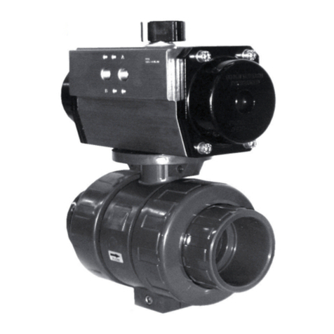
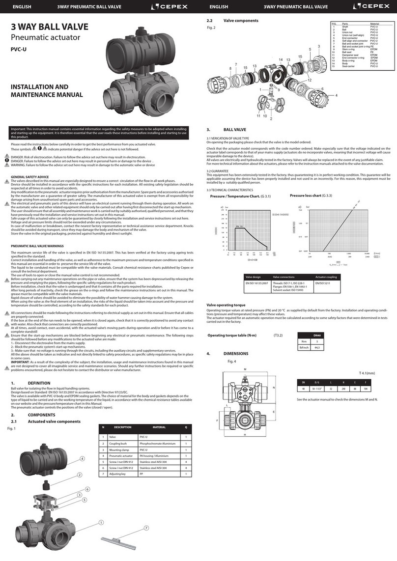
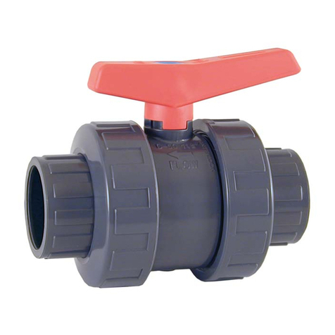
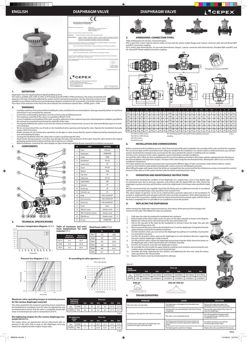
Cepex STD Manual

STD BUTTERFLY VALVES
Electric actuator
INSTALLATION AND
MAINTENANCE MANUAL
VÁLVULAS MARIPOSA STD
Actuador eléctrico
MANUAL DE INSTALACIÓN Y
MANTENIMIENTO
VANNES PAPILLON STD
à actionneur électrique
MANUEL D’INSTALLATION ET
D’ENTRETIEN
VÁLVULAS DE BORBOLETA STD
Atuador elétrico
MANUAL DE INSTALAÇÃO E
MANUTENÇÃO
VALVOLE A FARFALLA STD
Attuatore elettrico
MANUALE DI INSTALLAZIONE E
MANUTENZIONE
STD Absperrklappen
Elektrischer Stellantrieb
INSTALLATIONS- UND
WARTUNGSANLEITUNG

2

3
ENGLISH PAGE 04
ESPAÑOL PAGE 12
FRANÇAIS PAGE 20
PORTUGUÊS PAGE 28
ITALIANO PAGE 36
DEUTSCH PAGE 44

4
ENGLISHSTD ELECTRIC BUTTERFLY VALVE
Please read the instructions below carefully in order to get the best performance from your actuated valve.
These symbols indicate potential danger if the advice set out here is not followed.
DANGER. Risk of electrocution. Failure to follow the advice set out here may result in electrocution.
DANGER. Failure to follow the advice set out here may result in personal harm or damage to the device.
WARNING. Failure to follow the advice set out here may result in damage to the automatic valve or device.
GENERAL SAFETY ADVICE
The valves described in this manual are especially designed to ensure a correct circulation of the ow in all work phases.
Device should be installed in accordance with the specic instructions for each installation. All existing safety legislation should be
respected at all times in order to avoid accidents.
Any modication to the electric actuator requires prior authorisation from the manufacturer. Spare parts and accessories authorised
by the manufacturer are a guarantee of greater safety. The manufacturer of this actuated valve is exempt from all responsibility for
damage arising from unauthorised spare parts and accessories.
The electrical parts of this device will have an electrical current running through them during operation. All work on the automatic
valve and other related equipment should only be carried out after having rst disconnected the start up mechanism.
The user should ensure that all assembly and maintenance work is carried out by suitably authorised, qualied personnel, and that
they have previously read the installation and service instructions set out in this manual.
Safe usage of this actuated valve can only be guaranteed by closely following the installation and service instructions set out here.
Voltage should not be exceeded under any circumstances.
In case of malfunction or breakdown, contact the nearest factory representative or technical assistance service department. Knocks
should be avoided during transport, since they may damage the body and mechanism of the valve.
Store the valve in the original packaging, protected against humidity, environmental damages and direct sunlight.
ELECTRIC BUTTERFLY VALVE WARNINGS
The maximum service life of the valve is specied in EN ISO 16136. This has been veried at the factory using ageing tests specied
in the standard.
Correct installation and handling of the valve, as well as adherence to the maximum pressure and temperature conditions specied
in this manual are essential in order to preserve the service life of the valve.
The liquid to be conducted must be compatible with the valve materials. Consult chemical resistance charts published by Cepex or
ask to the Cepex technical department.
The use of tools to open or close the manual valve control is not recommended.
Before carrying out any maintenance operations on the pipe or valve, ensure that the system has been depressurised by releasing
the pressure and emptying the pipes, following the specic safety regulations for each product.
Before installation, check that the valve is undamaged and that it contains all the parts required for installation.
After long periods of inactivity, check the grease on the o-rings and follow the maintenance instructions set out in this manual. The
grease must be compatible with the valve materials.
Rapid closure of valves should be avoided to eliminate the possibility of water hammer causing damage to the system.
When using the valve as the nal element of an installation, the risks of the liquid should be taken into account and the pressure
and temperature should be controlled, according to the safety standards for each product.
Make all connections following the instructions referring to electrical supply set out in this manual. Ensure that all cables are correctly
connected.
If the box at the end of the run needs to be opened, disconnect all electrical supply before opening it; when it is closed again, check
that it is correctly positioned to avoid any contact with water. Also check that connectors are correctly positioned.
At all times, avoid contact, even accidental, with the motorised valve’s moving parts during operation and/or before it has come to
a complete standstill.
Ensure that the start-up mechanisms are blocked before beginning any electrical maintenance. The following steps should be
followed before any modication to the motorised valve:
1.- Disconnect from the main supply.
2.- Block the system’s start-up mechanisms.
3.- Make sure that no voltage is running through the circuits, including the auxiliary circuits and supplementary services.
All the above should be taken as indicative and not directly linked to the safety procedure as specic safety regulations may be in
place in some cases.
IMPORTANT: As a result of the complexity of the subject, the installation, usage and maintenance instructions found in this manual
are not designed to cover all imaginable service and maintenance scenarios. Should any further instructions be required or specic
problems encountered, please do not hesitate to contact the distributor or valve manufacturer.
In case of non correct working, check the Troubleshooting table (T13).
Important: This instruction manual contains essential information regarding safety measures to be adopted when installing and
starting up the equipment. It is therefore essential that the user reads these instructions before installing and starting to use this
product.

5
ENGLISH STD ELECTRIC BUTTERFLY VALVE
1. DEFINITION
Buttery valve electrically actuated for isolating the ow in uid handling systems.
The valve installation is compatible with ISO/DIN, BSi, ANSI and JIS installation standards (adapted to dierent ange
congurations).
Valve design based on Standard EN ISO 16136.
Actuator design based on ISO5211 - DIN3337 (valve connection), EN 60204 (safety), EN 50081-1 / EN 50082-1 / EN 50082-2 / EN
61000-4-2 / EN 61000-4-3 / EN 61000-4-4 / EN 61000-4-5 / EN 61000-4-6 / EN 61000-4-11 (electromagnetic compatibility).
The valve is available with PVC-U disc and body and EPDM sealing gasket.
The electric actuator controls the positions of the valve (closed / open). It is based on a quarter turn operation (90º), it works in
multivoltage power (24-230 VAC/VDC) and it has a protection of IP67.
2. COMPONENTS
N DESCRIPTION
1 Buttery valve
2 Actuation kit
3 Electric actuator
Fig. 1
1
2
3
3. DIMENSIONS
Verify the valve dimensions before starting the installation.
DN D B E E’ F H K M N L HOLES
65 63-75 - 2½” 135 81 150 18 48 125-145 169 110 181 4
80 90 - 3” 122 95 166 19 52 150-170 169 110 181 4
100 110 - 4” 145 106 178 19 59 180-192 196 110 181 4
125 125-140 - 5” 175 119 194 22 66 190-215 196 110 181 4
150 160 - 6” 209 133 210 24 72 240 254 214 235 4
200 200-225 - 8” 248 161 260 23 73 270-298 254 214 235 4
250 250-280 - 10” 400 199 283 29 114 355-362 254 214 235 12
300 315 - 12” 476 238 330 29 114 390-432 254 214 235 12
Fig. 2
1.1 VERICATION OF VALVE TYPE
On opening the packaging please check that the actuated valve is the model ordered (check the code with the Cepex catalogue).
Make especially sure that the voltage indicated on the actuator label corresponds to that of your main supply (incorrect voltage will
cause irreparable damage to the device).
All valves are electrically and hydraulically tested in the factory. Valves will always be replaced in the event of any justiable claim.
For more technical information about the actuators, please refer to the instruction manuals attached to the valve documentation.
1.2 GUARANTEE
This equipment has been extensively tested in the factory, thus guaranteeing it works well in Cepex recommended working
conditions (as specied in the Cepex technical catalogue or in the valve Datasheet). This guarantee will be applicable assuming the
device has been properly installed and not used in an incorrect way. For this reason, this equipment must be installed by a qualied
person.
Valve design Flanged dimensions Valve connections Other connections Actuator coupling
ISO 16136 EN 558-1,ANSI B16.5 Class 150,JIS B2220, BS/E EN 1090-1 ISO15494, ISO15493, ISO10931 EN/ISO 5211
T 2.2

6
ENGLISHSTD ELECTRIC BUTTERFLY VALVE
4. VALVE INSTALLATION
4.1 NECESSARY MATERIAL
- Torque wrench. Range 25 - 80 Nm (221-708 lbf/inch) for all the range. Hexagon socket sizes for each valve in the table T5.2
- Fix wrench (Table T5.2).
- Anti galling for the bolts.
4.2 INSTALLATION OF FLANGE ADAPTORS AND FLANGES IN THE PIPE IF NECESSARY
IMPORTANT: Verify all the chart dimensions (T 2.2) before starting the installation.
Before starting the installation process, check that you have all the parts needed for the valve assembly, and that the materials,
connection type and nominal pressure are suitable for the installation.
For solvent or welded connections, ensure also that the parts to be connected are of the same material and that the correct solvent
or welding tools are used.
To install the valve, follow best installation practice recommendations provided on the Cepex website and Cepex Technical
Catalogue, paying specic attention to thermal expansion and pipe alignment.
When lling the pipes with liquid, check that all the air has been purged from the system and that the initial pressure does not
exceed the nominal pressure of the valve, or that one of the system element with the lowest nominal pressure rating.
The valve could be assembled using standard ISO-DIN, ANSI, JIS and BS/E anges. Flat gaskets are not needed in the socket
couplings, as they are incorporated in the valve itself. Observe the tightening sequence of the screws on the anges (Fig. 5) and the
maximum tightening torque (T 5.2). All screws must be used in the ange in order to ensure proper operation of the valve.
The PP/PE sockets for butt welding must be chamfered as indicated in the diagram (Fig. 4) and table (T 4.2), to ensure correct
opening and closing of the disc.
Install the valve once the sockets are solvent-bonded and dry, to avoid problems with the adhesive (entry of the latter into the
valve). Ask for the solvent drying times with the manufacturer.
Flanges must be well centred on the valve (pay special attention to measurements DN100-DN125 and DN200). Misalignment on
assembly could cause problems with the valve operation (Fig. 3.2).
Look forward at the Technical catalogue in the www.cepex.com website for codes of the installation components.
Be aware of the H dimension for the valve installation (T 2.2)
IMPORTANT: At the time of gluing, do not leave adhesive rests in the at faces of the ange adaptors (parts in contact with the
valve).
In the sizes D250 and D315 it is recommended to use a valve support in the installation due its high weight.
DN D min. x
65 50.5 30º
80 70 30º
100 91.5 30º
125 113 30º
150 141 30º
200 191.5 20º
250 226 20º
300 296.5 20º
Fig. 3.1
Fig. 4
Pipe and chamfer
measurements
PP/PE sockets T 4.2
Fig. 3.2

7
ENGLISH STD ELECTRIC BUTTERFLY VALVE
D DN inch Screws (A2) Torque
(N·m)
Torque
(inch·lbs)
Torque
wrench
63 50 - 4xM16x120 25 221
24 mm
75 65 2 1/2” 4xM16x140 25 221
90 80 3” 8xM16x150 25 221
110 100 4” 8xM16x160 30 265
125 125 - 8xM16x170 35 310
140 125 5” 8xM16x170 35 310
160 150 6” 8xM20x200 40 354
30 mm
200 200 - 8xM20x210 50 442
225 200 8” 8xM20x230 50 442
250 250 - 12xM20x270 80 708
280 250 10” 12xM20x270 80 708
315 300 12” 12xM20x310 80 708
Screws and screw maximum tightening torque
Fig. 5
T 5.2
4.3 VALVE INSTALLATION
A) Introduce the valve in CLOSED position between the ange adaptors (where there have to be H dimension T 2.2).
Avoid dirty or strange elements in the gasket at faces.
When introducing the valve, be careful of not damaging the gaskets.
B) Install the bolts, nuts and washers following the order and the torque indicated in the Fig. 5 and T 5.2.
It will be necessary to install all the bolts in the ange holes, even if they do not x a valve hole. In other situations the valve could
not work correctly.
Is it always compulsory to use washers between ange and bolt or ange and nut.
C) Manual testing of the valve working.
Change the actuator selector handle in MANUAL position (B) MAN (Fig 6).
Open the valve turning the actuator wheel counterclockwise to the“90” position (Fig. 7). The valve must be opened without dif-
culty. If the opening or closing of the valve takes any inconvenience, check the Troubleshooting table (T 13)
Change again the actuator selector to (A) AUTO position (Fig 6).
4.4 ELECTRICAL CONNECTION
A) Check that the valve voltage indicated in the actuator label corresponds to your power supply.
B) Disassembly the power connector (GREY EN175301-803 A) to wire it following the electric diagram:
IMPORTANT: Use a wire of 8 to 10.5mm diameter and keep all the connector elements: o-rings, cable gland, etc. With a non ap-
propiate wire, the tightness degree (IP protection) could be lost.
Fig. 6 Fig. 7
1
3
2
CLOSE OPEN
N/(or)-
L/(or)+
FUSE
1
3
2
CLOSE OPEN
-
+
FUSE
VAC/VDC - 3 wires VDC - 2 wires
GREY PLUG
EN175301-803 FORM A

8
ENGLISHSTD ELECTRIC BUTTERFLY VALVE
C) In case of using voltage free positioners. Disassembly the positioning connector (BLACK DIN43650/C), for wiring it
following the electrical diagramm:
IMPORTANT: Use a wire of 5 to 6mm diameter and keep all the connector elements: o-rings, cable gland, etc. With a non
appropiate wire, the tightness degree (IP protection) could be lost.
D) Install both connectors to their respective bases and check the cycles of opening and closing (90 - 0) and position detection in
case of being installed.
IMPORTANT: The valve has always to be under electrical power to make work the internal heater anti-condensation so the
actuator doesn’t get damaged.
5. ACTUATED VALVE CHARACTERISTICS
Valve size Actuator
Model
Voltage 90º time Maximum
operational
torque
Maximum
break
torque
Operational Torque
Consumption
Maximum torque break
D63 D75 (DN50-65)
D90 (DN80)
J4 S035 24-240
VAC/VDC
50/60 Hz
10 s 35 Nm
309 in·lbf
38 Nm
359,3 in·lbf
24VDC - 0,45A - 10,77W
48VDC - 0,21A - 9,93W
110VDC - 0,07A - 7,70W
24 VAC - 0,59A - 14,20W
48 VAC - 0,34A - 16,37W
110 VAC - 0,14A - 15,73W
240 VAC - 0,10A - 23,76W
24VDC - 1,37A - 32,79W
48VDC - 0,59A - 28,20W
110VDC - 0,18A - 20,10W
24 VAC - 1,67A - 40,13W
48 VAC - 0,99A - 47,31W
110 VAC - 0,38A - 41,87W
240 VAC - 0,20A - 47,52W
D110 (DN100) J4 S055 24-240
VAC/VDC
50/60 Hz
13 s 55 Nm
486 in·lbf
60 Nm
530 in·lbf
24VDC - 0,42A - 10,19W
48VDC - 0,20A - 9,72W
110VDC - 0,07A - 7,50W
24 VAC - 0,58A - 13,89W
48 VAC - 0,33A - 15,73W
110 VAC - 0,14A - 15,73W
240 VAC - 0,09A - 22,70W
24VDC - 1,63A - 39,02W
48VDC - 0,67A - 32,31W
110VDC - 0,21A - 32,20W
24 VAC - 1,98A - 47,52W
48 VAC - 1,21A - 58,29W
110 VAC - 0,43A - 46,95W
240 VAC - 0,21A - 50,16W
D125 D140 (DN125) J4 S085 24-240
VAC/VDC
50/60 Hz
29 s 85 Nm
752 in·lbf
90 Nm
796 in·lbf
24VDC - 0,36A - 8,55W
48VDC - 0,17A - 8,24W
110VDC - 0,05A - 5,80W
24 VAC - 0,50A - 11,88W
48 VAC - 0,25A - 11,83W
110 VAC - 0,12A - 12,83W
240 VAC - 0,08A - 20,06W
24VDC - 1,22A - 29,30W
48VDC - 0,53A - 25,56W
110VDC - 0,16A - 17,90W
24 VAC - 1,50A - 36,01W
48 VAC - 0,86A - 41,18W
110 VAC - 0,33A - 36,54W
240 VAC - 0,18A - 42,77W
D160 (DN150)
D200 (DN200)
J4 S140 24-240
VAC/VDC
50/60 Hz
25 s 140 Nm
1239 in·lbf
170 Nm
1504 in·lbf
24VDC - 0,66A - 15,84W
48VDC - 0,30A - 14,25W
110VDC - 0,10A - 10,89W
24 VAC - 0,83A - 19,80W
48 VAC - 0,48A - 23,23W
110 VAC - 0,23A - 25,41W
240 VAC - 0,18A - 42,77W
24VDC - 2,53A - 60,72W
48VDC - 1,10A - 52,80W
110VDC - 0,39A - 42,35W
24 VAC - 3,30A - 79,20W
48 VAC - 1,79A - 86,06W
110 VAC - 0,72A - 78,65W
240 VAC - 0,44A - 105,60W
D250 (DN250)
D315 (DN300)
J4 S300 24-240
VAC/VDC
48 s 300 Nm
2665 in·lbf
350 Nm
3097 in·lbf
24VDC - 0,50A - 11,88W
48VDC - 0,22A - 10,56W
110VDC - 0,09A - 9,68W
24 VAC - 0,66A - 15,84W
48 VAC - 0,36A - 17,42W
110 VAC - 0,19A - 20,57W
240 VAC - 0,15A - 36,96W
24VDC - 2,70A - 64,68W
48VDC - 1,19A - 57,02W
110VDC - 0,39A - 42,35W
24 VAC - 3,30A - 79,20W
48 VAC - 1,87A - 89,76W
110 VAC - 0,77A - 84,70W
240 VAC - 0,47A - 113,52W
1
3
2
CLOSED OPEN
POSITIONER - VOLT FREE
BLACK PLUG
DIN 43650/C
Common characteristics for all the models:
- Voltage: 24 - 240 VAC/VDC 50/60 Hz
- Duty rating: 75%
- IP rating: IP 67
- Temperature resistance: -20º / 70º C | -4º / 158º F
- Limit switch: 4 SPTD micro
- Heating resistor: 3,5 W
- Plugs: Power (Grey plug) EN175301-803 FORM A | Volt free (Black plug) DIN 43650/C
T 8.1

9
ENGLISH STD ELECTRIC BUTTERFLY VALVE
5.1 INFORMATION ABOUT THE VALVE STATUS
The valve LED shows lighting information to inform the user about its status.
ACTUATOR OPERATIONAL STATUS LED STATUS
Actuator without power supply OFF
Actuator with power supply In open position: Green
In closed position: Red
Actuator working (ashing LED) Opening: sequence Red/Orange
Closing: sequence Green/Orange
Actuator with torque limit function ON, moving from ... to ...
(ashing LED)
From open to close: sequence Red/O
From close to open: sequence Green/O
Actuator in MANUAL mode (exceeded time) Symmetric sequence: Orange/O
Actuator without power and working with the BSR system.
MAX 3 minutes
BSR NC: sequence Red/O
BSR NO: sequence Green/O
Battery protection. Danger - The battery needs recharging.
BSR disabled.
Asymmetric sequence Orange/O
Actuator with DPS Stop: Blue
Opening: seq. Blue/Green
Closing: seq. Blue/Red
6. BSR OPTION
Security system in case of electrical failure, the actuator which is tted with the BSR plug-in failsafe system, will go to the
predetermined position: NO (Normally Open) or NC (Normally Closed).
IMPORTANT: It is recommended that the electric valve could have an independent fuse system to protect it from other electrical
elements in line as pumps.
7. SET UP AND OPERATION
If adhesive has been used for the pipe union, please check the drying conditions of the adhesive (recommended by the
manufacturer) before passing uid through the installation.
First of all, let pass uid at low pressure by the valve and check both positions, open and closed; if the installation is well done, it
must show no leakage. After this checking, the installation could work normally.
It is very important to purgue the air in the installation, if not the valve could not work correctly.
Respect always the system conditions recommended by the manufacturer (pressure, temperature, chemical resistance, etc.) in
the valve, pipes, ttings, etc. Conditions explained in the Cepex Technical Catalogue and in the Hydraulic concepts in the Cepex
website.
ACTUATOR MODEL J4 S35 J4 S55 J4 S85 J4 S140 J4 S300
Nº working operation without recharge, with 100% battery charge 10 10 10 4 4
Battery consumption / working operation 21 min 48 min 58 min 30 min 50 min
Recharge time / working operation 3,0 W 6,8 W 8,3 W 23 W 23 W
Full charge time 100% 28 h 28 h 28 h 54 h 54 h
Current / one working operation with battery 14 mA 31,6 mA 38,6 mA 15,1 mA 25,7 mA

10
8.1 VALVE EXTRACTION
A) Depressurize the installation before the extraction of the valve.
B) Clean carefully all the valve parts before disassembling it. Check for the possibility of sediments or aggressive product rests. It is
recommended to use always protection glasses and gloves.
C) Turn the disc almost to closed position.
D) Loose up the ange bolts gradually and take them o of the installation. It is possible they could be blocked, specially if no anti
galling has been used in the installation.
E) Extract the valve from the installation taking special care of the sealing gasket.
8.2 REPLACING THE SEALING GASKET
If the sealing gasket needs to be replaced, proceed as follows:
A) Ensure that the system is depressurised by releasing the pressure and emptying the pipes, following
the specic safety regulations for each product. Also check the temperature of the liquid and follow
safety standards for temperature.
B) Remove the valve from the installation.
C) Remove the actuator (section 8.3).
D) Remove the ring (8). Take o the cap (7) and remove the screw (12).
E) Tap on the shaft (6) with a rubber mallet until the bearing (4) is exposed from the bottom (Fig. 9.1).
F) Once the bearing is out, remove the shaft (6), turn it and re-insert it (Fig. 9.2) from the bottom.
G) Tap again until the bearings (4 and 5) emerge from the top. Remove the shaft again.
H) Remove the disc by pressing in the direction of the liquid ow.
I) Remove the sealing gasket. Fit the new sealing gasket; it needs to be folded and positioned so that it
lines up with the shaft, according to the gasket indicator tab (Fig. 10).
IMPORTANT: Before installing the new gasket, check the condition of the O-rings (9 and 11).
Fig. 9.1 Fig. 9.2
Fig. 10
Fig. 11
N DESCRIPTION MATERIAL
1Body PVC-U
2Sealing gasket EPDM
3Disc PVC-U
4Bearing PP-GR
5Bearing PP-GR
6Shaft Zinc plated steel
7Cap PP
8Elastic ring SS AISI-304
9Shaft o-ring EPDM
10 Washer SS AISI-304
11 Shaft o-ring EPDM
12 Screw SS AISI-304
5
1
8
6
10
12
7
11
4
8
3
8
2
11
4
9
8. MAINTENANCE
The Cepex buttery valve doesn’t need any special maintenance if it’s correctly installed, but some actions are recommended to
enlarge its life and guarantee its perfect working:
If the system doesn’t have uid due to inactivity or wintering, it is recommended to leave the valve in open position.
It is necessary to open/close the valves which are in the same position during a long time, usually once or twice per month,
specially if they are D200, D250 or D315. With this action we could decrease the overexertion caused by the inactivity and we will
increase the life of the valve.
If the valve has been closed during a long time, we recommend to open it manually the rst time.
It is recommended to disassembly the valve and lubricate the gasket with solid grease in silicone base once a year, specially for the
valves with low activity.
It is recommended that the condition of the sealing gasket be regularly checked, since it may show signs of mechanical wear due
to pressure, handling and contact with the liquid. The sealing gasket should be greased in the disc contact area (the grease must
be compatible with the materials of the gasket and the disc). It is also advisable to regularly check that the ange xing nuts are
tightened correctly, as per the recommended torque values specied above (T5.2).
ENGLISHSTD ELECTRIC BUTTERFLY VALVE

11
8.3 MOUNT AND DISMANTLE THE ACTUATOR
If the actuator or the valve needs to be replaced, proceed as follows (Fig. 12):
A) Move the buttery valve to the closed position.
B) Remove the wires from the actuator.
C) Remove the screws, the washers and the nuts (C) from the mounting clamp attached to the valve using an allen key*.
D) Remove the actuator (2) with the mounting clamp (4) from the bare shaft valve (1).
E) Remove the screws (D) from the mounting clamp in order to dismantle the actuator (2) from the mounting clamp (4).
F) In case the actuator needs to be be replaced by a handle, also remove the coupling bush (3). Look at the Cepex spare parts
document to nd the necessary components.
In order to assemble a new actuator or a new valve, proceed in the opposite direction to the description above.
* IMPORTANT: For valves D160 it will be necessary to use a short allen key, as the regular ones does not t into the space.
ENGLISH STD ELECTRIC BUTTERFLY VALVE
Fig. 12
9. TROUBLESHOOTING T 13
FAULT POSSIBLE CAUSE FAULT CLEARANCE
The disc does not fully open
or close.
The sockets were not correctly bevelled. Disassemble the valve and bevel the sockets as indicated
in table T4.2.
Foreign materials in the compartment (adhesive, etc.). Disassemble the valve and check for obstructions in the
disc and gasket contact area.
Excessive opening or closing
torque.
The valve has been inactive for a long time. Operate with an auxiliary release key (not the plastic
handle).
Disassemble the valve and lubricate the sealing gasket.
High temperatures or chemicals can cause damage to
the gasket.
Check the chemical compatibility of the liquid with the
disc and the working temperature. Replace the gasket.
Excessive ange torque. Tighten anges as indicated in table T5.2.
Misalignment between sockets and valve. Disassemble the valve and reassemble with concentric
alignment (observe the correct tightening sequence and
torque).
Dirty, adhesive or strange elements in the gaskets or
ange adaptors
Clean carefully the dirty components
The valve is not completely
watertight in the sockets.
Misalignment between sockets and valve. Disassemble the valve and reassemble with concentric
alignment (observe the correct tightening sequence and
torque).
Flange screws not tight enough. Tighten anges as indicated in table T5.2.
The valve is not completely
watertight at the sealing
gasket.
Inadequate chemical resistance.
Temperature out of range.
Excess pressure.
Abrasive elements.
Check compliance with the specications in this
document.
Damaged gasket. Replace the gasket.
The valve does not open or
close.
Lack of current. Check power supply to the actuator.
The valve does not close
completely.
The actuator stroke is not well adjusted to the valve. Check adjustment limits according to the actuator manual.
The torque of the valve has increased above the
calculated value.
Check the valve: obstructions in the disc or malfunction
of the valve.

12
ESPAÑOLVÁLVULA MARIPOSA ELÉCTRICA STD
Para obtener el mejor funcionamiento de la válvula actuada, es recomendable leer con atención las siguientes instrucciones.
Estos símbolos indican peligro potencial si no se siguen las recomendaciones aquí indicadas.
PELIGRO. Riesgo de electrocución. No seguir las recomendaciones puede provocar electrocución.
PELIGRO. No seguir las recomendaciones puede provocar daños personales o daños al equipo.
ADVERTENCIA. No seguir las recomendaciones puede provocar daños a la válvula automática o al equipo.
RECOMENDACIONES GENERALES DE SEGURIDAD
Las válvulas descritas en este manual han sido especialmente diseñadas para asegurar la correcta circulación del ujo en todas las
fases de trabajo.
El equipo debe ser instalado de acuerdo con instrucciones especícas. Las advertencias de seguridad deben ser respetadas en todo
momento para evitar accidentes.
Cualquier modicación del actuador requiere una autorización previa del fabricante. Los recambios y accesorios autorizados son una
garantía de mayor seguridad. El fabricante de la válvula motorizada renuncia cualquier responsabilidad derivada del daño causado
por el uso de recambios o accesorios no autorizados.
Durante la operación, las partes eléctricas o electrónicas reciben voltaje. Trabajar en la válvula automática u otro equipo relacionado
sólo puede ser ejecutado después de haber desconectado el mecanismo de arranque.
El usuario debe asegurarse que los trabajos de montaje y mantenimiento siempre son realizados por personal autorizado y
cualicado, y que éste ha leído atentamente las instrucciones de instalación y servicio contenidas en este manual.
La seguridad de funcionamiento de esta válvula actuada sólo puede ser garantizada con el cumplimiento estricto de las instrucciones
de instalación y servicio. Las limitaciones de voltaje no pueden ser sobrepasadas en ninguna circunstancia.
En caso de defectos de funcionamiento o avería, contactar con el representante de fábrica más cercano o el servicio de asistencia
técnica de fábrica. Evitar golpes durante el transporte, ya que éstos pueden dañar el cuerpo o el mecanismo de la válvula.
Almacenar la válvula en su embalaje original, proteger contra la humedad y la exposición directa al sol.
ADVERTENCIAS DE LA VÁLVULA DE MARIPOSA ELÉCTRICA
La vida máxima de servicio de la válvula está especicada en la norma EN ISO 16136. Ésta ha sido vericada en fábrica con pruebas
de envejecimiento especicadas en la norma.
La correcta instalación y manejo de la válvula, así como el cumplimiento de las condiciones de presión máxima y temperatura
especicadas en este manual son esenciales para preservar la vida de la válvula.
El líquido conducido debe ser compatible con los materiales de la válvula. Consultar la tabla de resistencia química publicado en la
website de Cepex o consultar con el departamento técnico de Cepex.
No es recomendado el uso de herramientas para abrir o cerrar el control manual de la válvula.
Antes de llevar a cabo operaciones de mantenimiento en la tubería o la válvula, asegurarse que el sistema está despresurizado
liberando la presión y vaciando las tuberías, siguiendo las regulaciones de seguridad especícas de cada elemento.
Antes de la instalación, comprobar que la válvula no ha sufrido daños y que contiene todas las partes necesarias para la instalación.
Después de largos periodos de inactividad, comprobar la grasa de las juntas y seguir las instrucciones de mantenimiento conteni-
das en este manual. La grasa debe ser compatible con los materiales de la válvula.
Es importante evitar el cierre rápido de las válvulas para eliminar la posibilidad de golpes de ariete que causen daño al sistema.
Cuando se usa la válvula como elemento nal de una instalación, tener en cuenta los riesgos del líquido y controlar la presión y la
temperatura, de acuerdo con los estándares de cada producto.
Realizar todas las conexiones siguiendo la instrucción referida al suministro eléctrico contenida en este manual. Asegurarse que
todos los cables están correctamente conectados.
En caso de necesitar abrir la caja al nal de carrera, al cerrarla de nuevo, comprobar que está posicionada correctamente para evitar
cualquier contacto con el agua. También comprobar que los conectores están situados correctamente.
En todo momento, evitar contacto, incluso accidental, con las partes móviles de la válvula actuada durante la operación y/o antes
de que haya llegado al cierre completo.
Antes de empezar cualquier mantenimiento eléctrico, asegurarse que los mecanismos de arranque están bloqueados. Es
recomendable seguir los siguientes pasos antes de cualquier alteración de de la válvula actuada:
1.- Desconectar del suministro general.
2.- Bloquear los sistemas de arranque del sistema.
3.- Asegurarse que no hay voltaje corriendo a través de los circuitos, incluyendo circuitos auxiliares y servicios suplementarios.
Todo lo indicado anteriormente debe ser tomado como indicativo y no directamente ligado a procedimientos de seguridad, ya que
en algunos casos puede haber normas de seguridad especícas.
IMPORTANTE: Como resultado de la complejidad del sujeto, las instrucciones de instalación, uso y mantenimiento contenidas
en este manual no están designadas para cubrir cualquier escenario imaginable de servicio y mantenimiento. Si requiere otras
instrucciones o se encuentra con problemas especícos, por favor no dude en contactar con su distribuidor o el fabricante de la
válvula.
En caso de funcionamiento incorrecto, consultar la tabla de Solución de problemas (T13).
Importante: Este manual de instrucciones contiene información esencial concerniente a medidas de seguridad a adoptar en la
instalación y puesta en marcha el equipo. Por tanto, es importante que el usuario lea estas instrucciones antes de instalar y usar
este producto.

13
ESPAÑOL VÁLVULA MARIPOSA ELÉCTRICA STD
1. DEFINICIÓN
Válvula de mariposa actuada eléctricamente para aislar el caudal en sistemas de conducción de uidos.
La instalación de la válvula es compatible con los siguientes standards ISO/DIN, BSi, ANSI y JIS (está adaptada a distintas
conguraciones de brida).
El diseño de la válvula está basado en la Normativa EN ISO 16136.
El diseño del actuador está basado en ISO5211 - DIN3337 (conexión a válvula), EN 60204 (seguridad), EN 50081-1 / EN 50082-
1 / EN 50082-2 / EN 61000-4-2 / EN 61000-4-3 / EN 61000-4-4 / EN 61000-4-5 / EN 61000-4-6 / EN 61000-4-11 (compatibilidad
electromagnética).
La válvula está disponible con disco y cuerpo de PVC-U y junta de cierre EPDM.
El actuador eléctrico controla las posiciones de la válvula (abierta / cerrada). Está basado en una operación de cuarto de vuelta
(90º), funciona con entrada multivoltaje (24-230 VAC/VDC) y tiene una protección de IP67.
2. COMPONENTES
N DESCRIPCIÓN
1 Válvula de mariposa
2 Kit de actuación
3 Actuador eléctrico
Fig. 1
1
2
3
3. DIMENSIONES
Vericar las dimensiones de la válvula antes de empezar la instalación.
DN D B E E’ F H K M N L HOLES
65 63-75 - 2½” 135 81 150 18 48 125-145 169 110 181 4
80 90 - 3” 122 95 166 19 52 150-170 169 110 181 4
100 110 - 4” 145 106 178 19 59 180-192 196 110 181 4
125 125-140 - 5” 175 119 194 22 66 190-215 196 110 181 4
150 160 - 6” 209 133 210 24 72 240 254 214 235 4
200 200-225 - 8” 248 161 260 23 73 270-298 254 214 235 4
250 250-280 - 10” 400 199 283 29 114 355-362 254 214 235 12
300 315 - 12” 476 238 330 29 114 390-432 254 214 235 12
Fig. 2
1.1 VERIFICACIÓN DEL TIPO DE VÁLVULA
Al abrir el embalaje comprobar que la válvula actuada es el modelo pedido (comprobar el código en el catálogo Cepex).
Asegurarse especialmente que el voltaje indicado en la etiqueta del actuador corresponde con el suministro eléctrico (voltajes
incorrectos causarán daños irreparables al producto).
Todas las válvulas han sido probadas eléctricamente e hidráulicamente en fábrica. Las válvulas serán reemplazadas en caso de una
queja justicada.
Para más información técnica sobre los actuadores, consulte los manuales de instrucciones adjuntos a la documentación de la
válvula.
1.2 GARANTÍA
Este equipo ha sido extensivamente probado en fábrica, garantizando su buen funcionamiento bajo las condiciones de trabajo
recomendadas por Cepex (tal y como se especica en el Catálogo Técnico Cepex o en la Ficha Técnica de la válvula). Esta garantía
será aplicable asumiendo que la válvula ha sido correctamente instalada y no se usa de modo incorrrecto. Por esta razón, el equipo
debe ser instalado por personal cualicado.
Diseño válvula Dimensiones de bridas Conexiones válvula Otras conexiones Acoplamiento actuador
ISO 16136 EN 558-1,ANSI B16.5 Class 150,JIS B2220, BS/E EN 1090-1 ISO15494, ISO15493, ISO10931 EN/ISO 5211
T 2.2

14
4. INSTALACIÓN DE LA VÁLVULA
4.1 MATERIAL NECESARIO
- Llave de torsión. Rango 25 - 80 Nm (221-708 lbf/inch) para toda la gama. Medidas de la cabeza hexagonal para cada válvula en la
tabla T5.2
- Llave ja (Tabla T5.2).
- Antigripante para tornillería.
4.2 INSTALACIÓN DE LOS MANGUITOS PORTABRIDAS Y LAS BRIDAS EN LA TUBERÍA SI ES NECESARIO
IMPORTANTE: Vericar todas las dimensiones de la tabla (T 2.2) antes de empezar la instalación.
Antes de empezar el proceso de instalación, comprobar que se tienen todos los componentes necesarios para el ensamblaje de la
válvula, y que los materiales, tipo de conexión y presión nominal són correctos para la instalación.
Para conexiones encoladas o soldadas, asegurar también que las partes que se van a conectar son del mismo material y que se
están usando las herramientas adecuadas para encolar o soldar.
Para instalar la válvula, seguir las recomendaciones para una instalación correcta que encontrará en la web cepex y en el Catálogo
Técnico Cepex, prestando atención especial a la expansión térmica y a la alineación de la tubería.
Cuando se llenen las tuberías con líquido, comprobar que todo el aire ha sido purgado del sistema y que la presión inicial no
excede la presión nominal de la válvula, o aquella del elemento con la menor presión nominal del sistema.
La válvula puede ser instalada usando el standard de bridas ISO-DIN, ANSI, JIS o BS/E. NO es necesario usar juntas planas para
las bridas, ya que la válvula misma las incorpora. Observar la secuencia de apriete de los tornillos en las bridas (Fig. 5) y el par de
apriete máximo (T 5.2). Deben usarse todos los tornillos en la brida a n de asegurar una correcta operación de la válvula.
Los manguito de PP/PE para soldadura a tope se deben chaanar tal y como se indica en el dibujo (Fig. 4) y en la tabla (T 4.2), para
asegurar la correcta apertura y cierre del disco.
Instalar la válvula una vez los manguitos hayan sido encolados y estén secos, para evitar problemas con el adhesivo (entrada
dentro de la válvula). Preguntar por los tiempos de secado al fabricante.
Las bridas deben estar bien centradas en la válvula (prestar especial atención a los diámetros DN100-DN125 y DN200). La
desalineación en el ensamblaje puede causar problemas con el funcionamiento de la válvula (Fig. 3.2).
Revisar el Catálogo Técnico Cepex en la web www.cepex.com para obtener los códigos de los elementos necesarios para la insta-
lación.
Prestar atención a la dimensión H para la instalación de la válvula (T 2.2)
IMPORTANTE: En el momento de encolar, no dejar restos de adhesivo en las caras planas de los manguitos portabridas (partes en
contacto con la válvula).
En las medidas D250 y D315 se recomienda usar un soporte en la instalación debido a su gran peso.
DN D min. x
65 50.5 30º
80 70 30º
100 91.5 30º
125 113 30º
150 141 30º
200 191.5 20º
250 226 20º
300 296.5 20º
Fig. 3.1
Fig. 4
Medidas de
chaán
Manguitos PP/PE T 4.2
Fig. 3.2
ESPAÑOLVÁLVULA MARIPOSA ELÉCTRICA STD

15
D DN inch Tornillo (A2) Par
(N·m)
Par
(inch·lbs)
Llave
63 50 - 4xM16x120 25 221
24 mm
75 65 2 1/2” 4xM16x140 25 221
90 80 3” 8xM16x150 25 221
110 100 4” 8xM16x160 30 265
125 125 - 8xM16x170 35 310
140 125 5” 8xM16x170 35 310
160 150 6” 8xM20x200 40 354
30 mm
200 200 - 8xM20x210 50 442
225 200 8” 8xM20x230 50 442
250 250 - 12xM20x270 80 708
280 250 10” 12xM20x270 80 708
315 300 12” 12xM20x310 80 708
Tornillos y par de apriete máximo
Fig. 5
T 5.2
4.3 INSTALACIÓN DE LA VÁLVULA
A) Introducir la válvula en posición CERRADA entre los manguitos protabridas (dónde debe haber un espacio correspondiente a la
dimensión H T 2.2).
Evitar la suciedad o elementos extraños en las caras planas de la junta.
Cuando se introduzca la válvula, tener precaución en no dañar las juntas.
B) Instalar los tornillos, tuercas y arandelas siguiendo el orden indicado en la Fig. 5 y la T 5.2.
Será necesario instalar todos los tornillos en los agujeros de la brida, incluso si no sirven para sujetar un agujero de la válvula. En
caso contrario la válvula podrá no funcionar correctamente.
Es necesario usar siempre arandelas entrela brida y el tornillo y entre la brida y la tuerca.
C) Comprobación manual del funcionamiento de la válvula.
Cambiar la palanca selectora del actuador a posición MANUAL (B) MAN (Fig 6).
Abrir la válvula girando el volante del actuador en dirección contraria a las agujas del reloj hasta la posición “90”(Fig. 7). La válvula
debe abrirse sin dicultad. Si la apertura o cierre de la válvula presenta algún inconveniente, revisar la tabla de Solución de proble-
mas (T 13).
Cambiar de nuevo el selector del actuador a la posición (A) AUTO (Fig 6).
4.4 CONEXIÓN ELÉCTRICA
A) Comprobar que el voltaje indicado en la etiqueta de la válvula corresponde a su suministro eléctrico.
B) Desmontar el conector de voltaje (GIS EN175301-803 A) para cablear iguiendo el siguiente esquema:
IMPORTANTE: Usar cable de 8 a 10.5mm de diámetro y mantener todos los elementos del conector: juntas, prensaestopas, etc.
Con un cable no apropiado, el grado de estanqueidad (protección IP) se puede perder.
Fig. 6 Fig. 7
1
3
2
CLOSE OPEN
N/(or)-
L/(or)+
FUSE
1
3
2
CLOSE OPEN
-
+
FUSE
VAC/VDC - 3 hilos VDC - 2 hilos
CONECTOR GRIS
EN175301-803 FORM A
ESPAÑOL VÁLVULA MARIPOSA ELÉCTRICA STD

16
C) En caso de usar los contactos auxiliares de posición. Desmontar el conector (NEGRO DIN43650/C), para cablear siguiendo
el siguiente esquema:
IMPORTANTE: Usar cable de 5 a 6mm de diámetro y mantener todos los elementos del conector: juntas, prensaestopas, etc. Con
un cable no apropiado, el grado de estanqueidad (protección IP) se puede perder.
D) Instalar ambos conectores a sus respectivas bases y comprobar los ciclos de abierto cerrado (90 - 0) y el detector de posición en
caso de haber sido instalado.
IMPORTANTE: La válvula siempre debe estar bajo tensión eléctrica para hacer funcionar la resistencia interna anti-condensación
para que el actuador no quede dañado.
5. CARACTERÍSTICAS DE LA VÁLVULA ACTUADA
Diámetro Modelo
de
actuador
Voltaje Tiempo
90º
Par máximo
de trabajo
Par máximo
de arranque
Consumo en par de
trabajo
Consumo en par de
arranque
D63 D75 (DN50-65)
D90 (DN80)
J4 S035 24-240
VAC/VDC
50/60 Hz
10 s 35 Nm
309 in·lbf
38 Nm
359,3 in·lbf
24VDC - 0,45A - 10,77W
48VDC - 0,21A - 9,93W
110VDC - 0,07A - 7,70W
24 VAC - 0,59A - 14,20W
48 VAC - 0,34A - 16,37W
110 VAC - 0,14A - 15,73W
240 VAC - 0,10A - 23,76W
24VDC - 1,37A - 32,79W
48VDC - 0,59A - 28,20W
110VDC - 0,18A - 20,10W
24 VAC - 1,67A - 40,13W
48 VAC - 0,99A - 47,31W
110 VAC - 0,38A - 41,87W
240 VAC - 0,20A - 47,52W
D110 (DN100) J4 S055 24-240
VAC/VDC
50/60 Hz
13 s 55 Nm
486 in·lbf
60 Nm
530 in·lbf
24VDC - 0,42A - 10,19W
48VDC - 0,20A - 9,72W
110VDC - 0,07A - 7,50W
24 VAC - 0,58A - 13,89W
48 VAC - 0,33A - 15,73W
110 VAC - 0,14A - 15,73W
240 VAC - 0,09A - 22,70W
24VDC - 1,63A - 39,02W
48VDC - 0,67A - 32,31W
110VDC - 0,21A - 32,20W
24 VAC - 1,98A - 47,52W
48 VAC - 1,21A - 58,29W
110 VAC - 0,43A - 46,95W
240 VAC - 0,21A - 50,16W
D125 D140 (DN125) J4 S085 24-240
VAC/VDC
50/60 Hz
29 s 85 Nm
752 in·lbf
90 Nm
796 in·lbf
24VDC - 0,36A - 8,55W
48VDC - 0,17A - 8,24W
110VDC - 0,05A - 5,80W
24 VAC - 0,50A - 11,88W
48 VAC - 0,25A - 11,83W
110 VAC - 0,12A - 12,83W
240 VAC - 0,08A - 20,06W
24VDC - 1,22A - 29,30W
48VDC - 0,53A - 25,56W
110VDC - 0,16A - 17,90W
24 VAC - 1,50A - 36,01W
48 VAC - 0,86A - 41,18W
110 VAC - 0,33A - 36,54W
240 VAC - 0,18A - 42,77W
D160 (DN150)
D200 (DN200)
J4 S140 24-240
VAC/VDC
50/60 Hz
25 s 140 Nm
1239 in·lbf
170 Nm
1504 in·lbf
24VDC - 0,66A - 15,84W
48VDC - 0,30A - 14,25W
110VDC - 0,10A - 10,89W
24 VAC - 0,83A - 19,80W
48 VAC - 0,48A - 23,23W
110 VAC - 0,23A - 25,41W
240 VAC - 0,18A - 42,77W
24VDC - 2,53A - 60,72W
48VDC - 1,10A - 52,80W
110VDC - 0,39A - 42,35W
24 VAC - 3,30A - 79,20W
48 VAC - 1,79A - 86,06W
110 VAC - 0,72A - 78,65W
240 VAC - 0,44A - 105,60W
D250 (DN250)
D315 (DN300)
J4 S300 24-240
VAC/VDC
48 s 300 Nm
2665 in·lbf
350 Nm
3097 in·lbf
24VDC - 0,50A - 11,88W
48VDC - 0,22A - 10,56W
110VDC - 0,09A - 9,68W
24 VAC - 0,66A - 15,84W
48 VAC - 0,36A - 17,42W
110 VAC - 0,19A - 20,57W
240 VAC - 0,15A - 36,96W
24VDC - 2,70A - 64,68W
48VDC - 1,19A - 57,02W
110VDC - 0,39A - 42,35W
24 VAC - 3,30A - 79,20W
48 VAC - 1,87A - 89,76W
110 VAC - 0,77A - 84,70W
240 VAC - 0,47A - 113,52W
1
3
2
CLOSED OPEN
POSITIONER - VOLT FREE
CONECTOR NEGRO
DIN 43650/C
Características comunes a todos los actuadores:
- Voltaje: 24 - 240 VAC/VDC 50/60 Hz
- Tiempo bajo tensión: 75%
- Grado de protección: IP 67
- Temperatura: -20º / 70º C | -4º / 158º F
- Interruptor nal de carrera: 4 SPTD micro
- Resistencia calefactora: 3,5 W
- Conectores: Voltaje (gris) EN175301-803 FORM A | Posición (negro) DIN 43650/C
T 8.1
ESPAÑOLVÁLVULA MARIPOSA ELÉCTRICA STD

17
5.1 INFORMACIÓN SOBRE EL ESTADO DE LA VÁLVULA
El LED en la válvula muestra información lumínica para informar al usuario sobre su estado.
ESTADO DE TRABAJO DEL ACTUADOR LED
Actuador sin corriente Apagado
Actuador con corriente En posición abierta: Verde
En posición cerrada: Rojo
Actuador trabajando (LED intermitente) Abriendo: secuencia Rojo/Naranja
Cerrando: secuencia Verde/Naranja
Actuador con función limitador de par ON, moviendo de ... a ...
(LED intermitente)
De abierto a cerrado: secuencia Rojo/Apagado
De cerrado a abierto: secuencia Verde/Apagado
Actuador en modo MANUAL (tiempo excedido) Secuencia simétrica: Naranja/Apagado
Actuador sin corriente y trabajando con el sistema BSR. MAX
3 minutos
BSR NC: secuencia Rojo/Apagado
BSR NO: secuencia Verde/Apagado
Protección de batería. Peligro - La batería necesita recarga. BSR
desabilitado.
Secuencia asimétrica Naranja/Apagado
Actuador con DPS Parado: Azul
Abriendo: secuencia Azul/Verde
Cerrando: secuencia Azul/Rojo
6. OPCIÓN BSR
Sistema de seguridad en caso de fallo eléctrico, el actuador que contiene el plug-in BSR sistema contra fallos, se moverá a la
posición predeterminada: NO (Normalmente Abierto) o NC (Normalmente Cerrado).
IMPORTANTE: Se recomienda que la válvula eléctrica pueda tener un sistema de fusibles independiente para protegerla de otros
elementos eléctricos en la línea como bombas.
7. INSTALACIÓN Y FUNCIONAMIENTO
Si se ha usado adhesivo para la unión de tubería, comprobar las condiciones de secado del adhesivo (recomendadas por el
fabricante) antes de pasar líquido por la instalación.
Antes que nada, dejar pasar uido a baja presión por la válvula y comprobar las dos posiciones, cerrada y abierta; si la instalación
está bien realizada, no debería presentar pérdidas. Después de esta comprobación, la instalación podrá trabajar normalmente.
Es muy importante purgar el aire de la instalación, si no la válvula podría no funcionar correctamente.
Respetar siempre las condiciones del sistema recomendadas por el fabricante (presión, temperatura, resistencia química, etc.) en la
válvula, accesorios, tubería, etc. Las condiciones se explican en el Catálogo Técnico Cepex y en los Conceptos Hidráulicos de la web
Cepex.
MODELO DE ACTUADOR J4 S35 J4 S55 J4 S85 J4 S140 J4 S300
Nº de operaciones sin recarga, con el 100% de la carga de batería 10 10 10 4 4
Consumo de batería / trabajando 21 min 48 min 58 min 30 min 50 min
Tiempo de recarga / trabajando 3,0 W 6,8 W 8,3 W 23 W 23 W
Tiempo para recarga máxima 100% 28 h 28 h 28 h 54 h 54 h
Corriente / una operación con batería 14 mA 31,6 mA 38,6 mA 15,1 mA 25,7 mA
ESPAÑOL VÁLVULA MARIPOSA ELÉCTRICA STD

18
8.1 EXTRACCIÓN DE LA VÁLVULA
A) Despresurizar la instalación antes de la extracción de la válvula.
B) Limpiar cuidadosamente todas las partes de la válvula antes de desmontarla. Comprobar la existencia de sedimentos o restos de
producto agresivo. Se recomienda usar siempre gafas protectoras y guantes.
C) Girar la compuerta hasta posición casi cerrada.
D) Desapretar los tornillos de la brida gradualmente y retiralos de la instalación. Es posible que los tornillos puedan estar
bloqueados, sobre todo si no se ha usado antigripante.
E) Extraer la válvula de la instalación prestando especial atención a la junta de cierre.
8.2 REEMPLAZAR LA JUNTA DEL DISCO
Si se necesita reemplazar la junta del disco, proceder según los siguientes pasos:
A) Asegurarse de que no hay presión en el sistema, bajando la presión y vaciando las tuberías, siguiendo
las instrucciones de seguridad especícas de cada producto. Comprobar también la temperatura del
líquido y seguir los standards de seguridad según temperatura.
B) Retirar la válvula de la instalación.
C) Retirar el actuador (section 8.3).
D) Retirar la junta (8). Quitar el tapón (7) y retirar el tornillo (12).
E) Golpear el eje (6) con un martillo de goma hasta que el casquillo (4) sea visible en la parte inferior (Fig.
9.1).
F) Una vez retirado el casquillo, quitar el eje (6), girarlo y reinsertarlo (Fig. 9.2) desde abajo.
G) Golpear de nuevo hasta que los casquillos (4 y 5) emerjan en la parte superior. Retirar el eje de nuevo.
H) Retirar la compuerta presionando en dirección al caudal del líquido.
I) Retirar la junta de la compuerta. Colocar la nueva junta; es necesario doblarla y posicionarla bien
alineada con el eje, de acuerdo con la etiqueta indicadora de la junta (Fig. 10).
IMPORTANTE: Antes de instalar la nueva junta, comprobar la condición de las juntas del eje (9 y 11).
Fig. 9.1 Fig. 9.2
Fig. 10
Fig. 11
N DESCRIPCIÓN MATERIAL
1Cuerpo PVC-U
2Junta compuerta EPDM
3Compuerta PVC-U
4Casquillo PP-GR
5Casquillo PP-GR
6Eje Zinc plated steel
7Tapón PP
8Anillo elástico SS AISI-304
9Junta eje EPDM
10 Arandela SS AISI-304
11 Junta eje EPDM
12 Tornillo SS AISI-304
5
1
8
6
10
12
7
11
4
8
3
8
2
11
4
9
8. MANTENIMIENTO
La válvula de mariposa Cepex no necesita mantenimiento especial si ha sido correctamente instalada, pero se recomiendan
algunas acciones para alargar su vida y garantizar un funcionamiento perfecto:
Si el sistema no tiene uido debido a inactividad o invernaje, se recomienda dejar la válvula en posición abierta.
Es necesario abrir/cerrar las válvulas que estén en la misma posición durante un periodo largo de tiempo, normalmente una vez o
dos al mes, especialmente con los diámetros D200, D250 o D315. Con esta acción podemos disminuir el sobreesfuerzo causado por
la inactividad e incrementaremos la vida útil de la válvula.
Si la válvula ha permanecido cerrada durante largo tiempo, recomendamos abrir manualmente la primera vez.
Se recomienda desmontar la válvula y lubricar la junta con grasa sólida con base de silicona una vez al año, especialmente para las
válvulas con poca actividad.
Se recomienda revisar la condición de la junta regularmente, ya que puede mostrar signos de desgaste mecánico debido a
la presión, uso o contacto con el líquido. La junta debe ser engrasada en el área de contacto con el disco (la grasa debe ser
compatible con los materiales de la junta y del disco). También se recomienda revisar regularmente que las tuercas de jación de la
brida estén jadas correctamente, reejando los valores de par de apriete de los tornillos especicados anteriormente (T5.2).
ESPAÑOLVÁLVULA MARIPOSA ELÉCTRICA STD

19
8.3 MONTAJE Y DESMONTAJE DEL ACTUADOR
Si se necesita reemplazar el actuador, proceder siguiendo los pasos (Fig. 12):
A) Mover la válvula a posición cerrada.
B) Retirar los cables del actuador.
C) Retirar los tornillos, arandelas y tuercas (C) de la brida de jación sujeta a la válvula, usando una llave Allen*.
D) Retirar el actuador (2) junto a la brida de jación (4) de la válvula (1).
E) Retirar los tornillos (D) de la brida de jación para poder separar el actuador (2) de la brida de jación (4).
F) En caso de que se necesite reeamplazar el actuador por una maneta, retirar también la extensión del eje (3). Comprobar el
documento Recambios Cepex para encontrar los componentes necesarios.
Para montar un nuevo actuador o una nueva válvula, proceder en sentido contrario de la descripción anterior.
* IMPORTANTE: Para válvulas D160 será necesario usar una llave Allen corta, ya que las standard no caben en el espacio
necesario.
Fig. 12
9. SOLUCIÓN DE PROBLEMAS T 13
ESPAÑOL VÁLVULA MARIPOSA ELÉCTRICA STD
PROBLEMA POSIBLE CAUSA SOLUCIÓN
La compuerta no abre o
cierra completamente.
Los manguitos no han sido correctamente chaanados. Desmontar la válvula y chaanar los manguitos como se
indica en la tabla T4.2.
Materiales extraños en el compartimento (adhesivo,
etc.).
Desmontar la válvula y comprobar si hay obstrucciones en
el área de contacto entre la compuerta y la junta.
Par excesivo de apertura
o cierre.
La válvula ha estado inactiva un largo período de
tiempo.
Manipular con una llave auxiliar (no la maneta de plástico).
Desmontar la válvula y lubricar la junta.
Altas temperaturas o productos químicos pueden
dañar el material de la junta.
Comprobar la compatibilidad química y la temperatura de
trabajo de los materiales. Reemplazar la junta.
Par excesivo de la brida. Apretar las bridas como indica la tabla T5.2.
Desalineación entre manguitos y válvula. Desmontar la válvula y volver a montar con alineamiento
concéntrico (observar el apriete y secuencia correctos).
Suciedad, adhesivo o elementos extraños en los
manguitos portabridas o juntas
Limpiar con cuidado la parte sucia
No hay estanqueidad
completa entre la válvula y
los manguitos.
Desalineación entre manguitos y válvula. Desmontar la válvula y volver a montar con alineamiento
concéntrico (observar el apriete y secuencia correctos).
Par insuciente de la brida. Apretar las bridas como indica la tabla T5.2.
No hay estanqueidad
completa en la junta del
cuerpo.
Resistencia química inadecuada.
Temperatura fuera de rango.
Exceso de presión.
Elementos abrasivos.
Comprobar el cumplimiento de especicaciones en este
documento.
Junta dañada. Reemplazar la junta.
La válvula no abre o no cierra. Falta de corriente. Comprobar la fuente de alimentación del actuador.
La válvula no cierra
completamente.
El par del actuador no está bien ajustado con el de la
válvula.
Comprobar los ajustes de acuerdo con el manual del
actuador.
El par de la válvula ha crecido por encima del valor
calculado.
Comprobar la válvula: obstrucciones en la bola o mal
funcionamiento.

20
FRANÇAISVANNE PAPILLON ÉLECTRIQUE STD
Lisez attentivement les instructions ci-dessous pour obtenir les meilleurs résultats de la vanne automatique.
Ces symboles signalent un danger potentiel si vous ne suivez pas le conseil fourni.
DANGER. Risque d’électrocution Si vous ne suivez pas le conseil fourni, vous risquez de vous électrocuter.
DANGER. Si vous ne suivez pas le conseil fourni, vous risquez de vous blesser ou d’endommager l’équipement.
AVERTISSEMENT. Si vous ne suivez pas le conseil fourni, vous risquez d’endommager l’appareil ou la vanne automatique.
CONSEILS DE SÉCURITÉ GÉNÉRAUX
Les vannes décrites dans ce manuel sont spéciquement conçues pour garantir la bonne circulation du ux dans toutes les phases
de travail.
L’appareil doit être installé conformément aux instructions spéciques de chaque installation. Toute législation existante relative à la
sécurité doit être respectée à tout moment an d’éviter les accidents.
Toute modication de l’actionneur électrique est soumise à l’autorisation préalable du fabricant. Les pièces de rechange et
accessoires agréés par le fabricant garantissent une plus grande sécurité. Le fabricant de cette vanne automatique décline toute
responsabilité en cas de dommage découlant de l’utilisation de pièces de rechange et d’accessoires non agréés.
Le courant circule dans les pièces électriques de cet appareil lorsqu’il est en marche. Pour manipuler la vanne automatique et tout
autre matériel connexe, le mécanisme de démarrage doit être mis hors tension.
L’utilisateur doit s’assurer que toute opération de montage et d’entretien est eectuée par une personne dûment qualiée et
autorisée et que cette dernière a lu les instructions d’installation et d’entretien énoncées dans ce manuel.
L’utilisation sûre de cette vanne automatique est uniquement garantie par le strict respect des instructions d’installation et
d’entretien énoncées dans ce manuel.
La tension maximale ne doit être en aucun cas dépassée.
En cas de dysfonctionnement ou de panne, contactez le représentant de l’usine le plus proche ou le service d’assistance technique.
Les coups doivent être évités lors du transport, car ils risquent d’endommager le corps et le mécanisme de la vanne.
Rangez la vanne dans son emballage d’origine, à l’abri de l’humidité, des dommages environnementaux et des rayons directs du
soleil.
AVERTISSEMENTS CONCERNANT LA VANNE PAPILLON ÉLECTRIQUE
La durée de vie maximale de la vanne est indiquée dans la norme ENISO16136. Elle a été vériée à l’usine à l’aide d’essais de
vieillissement indiqués dans la norme.
Pour préserver la durée de vie de la vanne, il est indispensable d’installer et de manipuler correctement la vanne, ainsi que de
respecter les conditions de pression et de température maximales indiquées dans ce manuel.
Le liquide conduit doit être compatible avec les matériaux de la vanne. Consultez les tableaux de résistance chimique publiés par
Cepex ou contactez le service technique de Cepex.
Il est déconseillé d’utiliser des outils pour ouvrir ou fermer la commande manuelle de la vanne.
Avant d’eectuer toute opération d’entretien sur le conduit ou la vanne, assurez-vous que le système a été dépressurisé en libérant
la pression et en vidant les conduits, conformément aux consignes de sécurité spéciques de chaque produit.
Avant de procéder à l’installation, vériez que la vanne n’est pas endommagée et qu’elle contient toutes les pièces nécessaires à
l’installation.
Si la vanne n’a pas été utilisée pendant une longue période, vériez la graisse sur les joints toriques et suivez les instructions
d’entretien indiquées dans ce manuel. La graisse doit être compatible avec les matériaux de la vanne.
Ne fermez pas les vannes rapidement pour éviter les éventuels coups de bélier qui endommageraient le système.
Lorsque la vanne est utilisée en tant qu’élément nal d’une installation, les risques liés au liquide doivent être pris en compte et la
pression et la température doivent être contrôlées, conformément aux normes de sécurité de chaque produit.
Réalisez tous les branchements conformément aux instructions relatives à l’alimentation électrique indiquées dans ce manuel.
Assurez-vous que tous les câbles sont correctement branchés.
Si vous devez ouvrir le boîtier de n de course, débranchez d’abord l’alimentation électrique. Une fois le boîtier refermé, vériez qu’il
est correctement placé pour éviter tout contact avec l’eau. Vériez également que les connecteurs sont bien positionnés.
Évitez toujours le contact, même accidentel, avec les pièces mobiles de la vanne motorisée lorsque l’appareil est en marche et/ou
tant qu’il n’est pas complètement arrêté.
Assurez-vous que les mécanismes de démarrage sont verrouillés avant de procéder à toute opération d’entretien électrique.
Eectuez les étapes suivantes avant toute modication de la vanne motorisée:
1.- Débranchez l’appareil de l’alimentation secteur.
2.- Verrouillez les mécanismes de démarrage du système.
3.- Vériez que les circuits, y compris les circuits auxiliaires et les services supplémentaires, sont totalement hors tension.
Les instructions ci-dessus sont indiquées à titre indicatif, elles ne sont pas à associer directement aux procédures de sécurité, car des
consignes de sécurité spéciques sont susceptibles d’être en vigueur.
IMPORTANT : Étant donné la complexité du sujet, les instructions d’installation, d’utilisation et d’entretien indiquées dans ce
manuel ne visent pas à couvrir l’intégralité des scénarios d’entretien et d’utilisation imaginables. Si vous avez besoin d’instructions
complémentaires ou si vous rencontrez un problème particulier, contactez le distributeur ou le fabricant de la vanne.
En cas de dysfonctionnement, consultez le tableau Dépannage (T13).
Important : Ce mode d’emploi contient des informations essentielles concernant les mesures de sécurité à respecter lors de
l’installation et du démarrage du matériel. Il est donc primordial que l’utilisateur lise ces instructions avant d’installer et d’utiliser
ce produit.
Table of contents
Languages:
Other Cepex Control Unit manuals

Cepex
Cepex EXTREME Series Manual

Cepex
Cepex PVC-U Series Manual

Cepex
Cepex Industrial Series User manual

Cepex
Cepex PVC-U User manual

Cepex
Cepex PVC-U Series User manual

Cepex
Cepex EXTREME Series Manual

Cepex
Cepex DN15 User manual

Cepex
Cepex EXTREME Series Manual

Cepex
Cepex EXTREME Series Manual

Cepex
Cepex PVC-U Manual
Popular Control Unit manuals by other brands

GKD
GKD 1S Series installation manual

Haws
Haws SP158B Installation, operation and maintenance instructions

Bardiani Valvole
Bardiani Valvole BBZK Operating and maintenance instructions

VIA Technologies
VIA Technologies ETX-8X90 user manual

McIntosh
McIntosh C39 owner's manual

Wabtec
Wabtec ASMB0878 Hardware Integration Manual