manuals.online logo
Brands
  1. Home
  2. •
  3. Brands
  4. •
  5. Chamberlain
  6. •
  7. Door Opening System
  8. •
  9. Chamberlain HCTDCU User manual

Chamberlain HCTDCU User manual

1
3
4
5
6
2
7
1Open the cover.
2Remove the chain guard.
3Align the key holes on the end of the rail with the cap screws on the chassis.
4Attach the rail to the chassis with the hardware provided.
5Move trolley to within 3 feet (.9 m) of the end of the rail.
6Wrap the chain around the output sprocket.
7Adjust the chain tension.
8Replace chain guard.
This QuickStart is intended to highlight a single gate/door
application. Each application is unique and it is the
responsibility of the purchaser, installer and end user to ensure
that the total gate/door system is installed and operated
properly. Refer to the installation manual for complete
information regarding installation, testing, and programming.
QuickStart
for single gate/door application
Model HCTDCU
INSTALLATION
01-38474 © 2016, LiftMaster – All Rights Reserved
845 Larch Avenue
Elmhurst, Illinois 60126-1196
LiftMaster.com
Connect rail to operator. Install vented plug.
Determine location for operator.
Mount the operator.
2016 UL 325 Gate Operators require use of LiftMaster
external monitored entrapment protection devices.
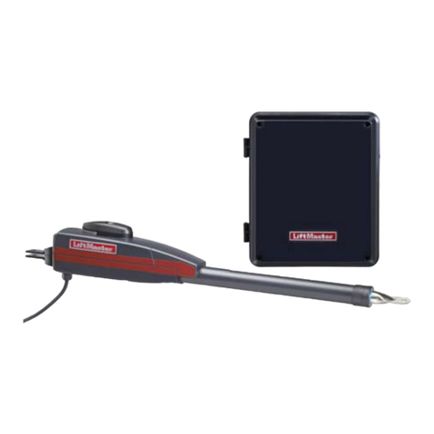
HCTDCU
Motor Unit
HCT08
8 Foot Rail
HCT10
10 Foot Rail
HCT12
12 Foot Rail
Temporary
Support Post
Header Bracket
Vented Plug
Header Bracket
OR
Concrete Anchor
1/2" x 3 1/2"
Brackets (not provided)
Flush Mount
Arm
Door Arm
DOOR INSTALLATION
Cap Screw
Chain Guard
Trolley
Within 3 feet (.9 m)
Top of Rail
1/4" (.64 cm) Max.
Turnbuckle
Hex Nut
Carriage Bolt
Nut
Washer
1Center the header bracket in the opening and
bolt or weld the header bracket to the wall. 2Lift the operator and align with center mark
on ceiling. Bolt the operator to the ceiling. 3Bolt or weld arm to gate/door.
1With the gate/door closed,
mark the center.
1Remove the dome plug from the
operator chassis.
2Remove the solid plug in the gear
reducer and replace it with the vented
plug (provided in bag with manual).
3Tighten the vented plug with a socket or
Allen wrench.
4Re-insert the dome plug.
2Open the gate/door and mark the
center point on the ceiling.
Dome Plug
DIAGNOSTICS
+
-
- -
3 2 1
10W 12V
10W 12V
Entrapment Zone
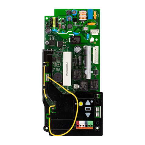
CONTROL BOARD
J15 Plug
Bridge Rectifier
7AH Solar Battery
Harness K94-36891
Power Wiring Sockets
(120 Vac
factory default)
Power Wiring Connector
Transformer
Orange
Orange
Battery
12V 7AH
Battery
12V 7AH
Gray
Blue
Brown
Purple
Black
Black
Black
Black
White
Green
HOT
NEUTRAL
GROUND
EMI BOARD
Photoelectric Sensors
White
Red
Red
Red
Red
AC Power Switch
Piggy Back
Solar Panels (Optional)
20W minimum - 60W maximum,
wired in series
Incoming Power
Blue
Brown
WIRING AND ADJUSTMENTS
INITIAL LIMITS AND FORCE ADJUSTMENT
1. Press and release the SET
OPEN and SET CLOSE buttons
simultaneously to enter limit
setting mode.
2. Press and hold one of the
MOVE GATE buttons to move
the gate/door to the open or
close limit.
3. Press and release the SET
CLOSE or SET OPEN button
depending on which limit is
being set.
4. Press and hold one of the
MOVE GATE buttons to move
the gate/door to the other
limit.
5. Press and release the SET
CLOSE or SET OPEN button depending on which limit is being set.
6. Cycle the gate/door open and close. This automatically sets the
force.
When limits are set properly the operator will automatically exit limit
setting mode.
FINE TUNE THE FORCE
The REVERSAL FORCE DIAL on the control board is used for fine
tuning the force in cases where wind or environmental changes
may affect the gate/door travel. Based on the length and weight of
the gate/door it may be necessary to make additional force
adjustments. The force setting should be high enough that the
gate/door will not reverse by itself nor cause nuisance
interruptions, but low enough to prevent serious injury to a
person. The force setting is the same for both the open and close
gate/door directions.
1. Open and close the gate/door
with the TEST BUTTONS.
2. If the gate/door stops or
reverses before reaching the
fully open or closed position,
increase the force by turning
the force control slightly
clockwise.
3. Perform the “Obstruction
Test” after every force setting
adjustment.
1. Open and close the gate/door with the TEST BUTTONS, ensuring
that the gate/door is stopping at the proper open and close limit
positions.
2. Place a solid object under the open gate/door. Ensure that the
gate/door, and the solid object can withstand the forces
generated during this obstruction test.
3. Run the gate/door in the close direction. The gate/door should
stop and reverse upon contact with the solid object. If the gate/
door does not reverse off the solid object, reduce the force
setting by turning the force control slightly counter-clockwise.
The gate/door should have enough force to reach both the open
and close limits, but MUST reverse after contact with a solid
object.
Are all the wiring and connections tightly connected?
Is the AC power on? If the operator is left running on battery only, it
will drain the battery and will result in a service call.
Check the batteries and battery connections. Make sure there are two
12V batteries. Replace batteries if depleted to less than 20V.
Remove the protective anti-scratch film from the photoelectric
sensors. Leaving the film on can result in poor sensitivity as the film
decays/yellows/peels.
Confirm whether the site should be fail safe or secure and set the
operator accordingly.
Confirm operation of the following (if applicable):
Entrapment protection devices
Loops
TES relay
SOS/emergency transponders
Check operation of ALL legacy receivers using the MAX transmitter
Timer-to-Close setting
Quick close setting
Anti-tailgate setting
Check the following before leaving the site:
Turn off the AC power from the main power source circuit
breaker. Connect the earth ground rod, incoming power, and
batteries (see images below). The operator can be wired for 120
or 240 Vac by choosing the desired power wiring socket on the
EMI board. Refer to your manual for complete wiring
information.
The HCTDCU provides a high speed open option to help flow in
high traffic areas. Select the open speed using the BIPART
DELAY switch.
BIPART DELAY OFF (default) = 8 in./sec. open speed
BIPART DELAY ON (fast) = 11 in./sec. open speed
Install Monitored Entrapment Protection Device Connect Power Wiring and Earth Ground Rod Set Open Speed
Set the Limits and Force
Perform the Obstruction Test
Installation Checklist
This operator contains an inherent (internal) entrapment protection
system and REQUIRES the addition of a LiftMaster external
monitored entrapment protection system (non-contact photoelectric
sensor or contact edge sensor) for EACH entrapment zone prior to
gate movement. System includes six monitored entrapment
protection inputs capable of covering all entrapment zones. Refer to
the manual for complete information.

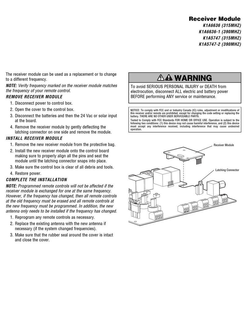
Other manuals for HCTDCU

1

Other Chamberlain Door Opening System manuals

Chamberlain DKK Series User manual

Chamberlain

Chamberlain DKK Series User manual

Chamberlain 878MAX User manual

Chamberlain

Chamberlain 878MAX User manual

Chamberlain 9747E Series User manual

Chamberlain

Chamberlain 9747E Series User manual

Chamberlain T User manual

Chamberlain

Chamberlain T User manual

Chamberlain T User manual

Chamberlain

Chamberlain T User manual

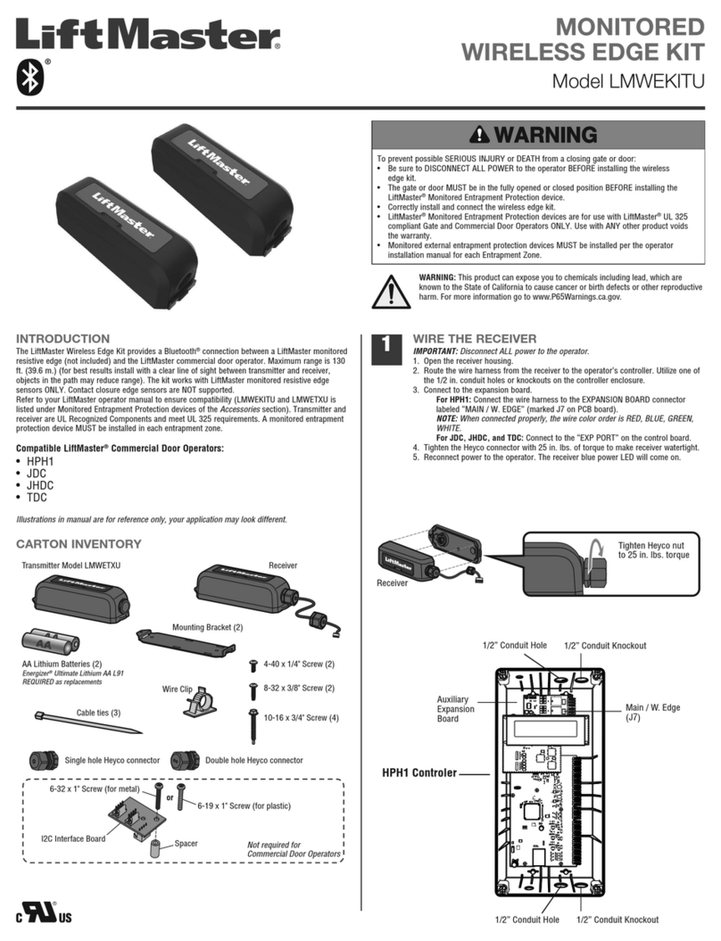
Chamberlain LMWEKITU User manual

Chamberlain

Chamberlain LMWEKITU User manual

Chamberlain ATS 2113X 1/2 HP User manual

Chamberlain

Chamberlain ATS 2113X 1/2 HP User manual

Chamberlain LiftMaster Premium 8355 User manual

Chamberlain

Chamberlain LiftMaster Premium 8355 User manual

Chamberlain GSD series User manual

Chamberlain

Chamberlain GSD series User manual

Chamberlain DDO8900W User manual

Chamberlain

Chamberlain DDO8900W User manual

Chamberlain Liftmaster MT5011 User manual

Chamberlain

Chamberlain Liftmaster MT5011 User manual

Chamberlain K001D8398-1 User manual

Chamberlain

Chamberlain K001D8398-1 User manual

Chamberlain CPS-U User manual

Chamberlain

Chamberlain CPS-U User manual

Chamberlain T User manual

Chamberlain

Chamberlain T User manual

Chamberlain 883LM User manual

Chamberlain

Chamberlain 883LM User manual

Chamberlain K1A6636 User manual

Chamberlain

Chamberlain K1A6636 User manual

Chamberlain ELITE Series User manual

Chamberlain

Chamberlain ELITE Series User manual

Chamberlain 050DCRJWFMC User manual

Chamberlain

Chamberlain 050DCRJWFMC User manual

Chamberlain LJ8900W User manual

Chamberlain

Chamberlain LJ8900W User manual

Chamberlain MyQ Garage User manual

Chamberlain

Chamberlain MyQ Garage User manual

Chamberlain LA400DC User manual

Chamberlain

Chamberlain LA400DC User manual

Chamberlain Motorlift ML700 User manual

Chamberlain

Chamberlain Motorlift ML700 User manual

Chamberlain LiftMaster Professional RDO800 Series User manual

Chamberlain

Chamberlain LiftMaster Professional RDO800 Series User manual

Chamberlain LiftMaster PROFESSIONAL 76LM User manual

Chamberlain

Chamberlain LiftMaster PROFESSIONAL 76LM User manual

Popular Door Opening System manuals by other brands

Genetec Synergis IX installation manual

Genetec

Genetec Synergis IX installation manual

LCN COMPACT 6400 Series installation instructions

LCN

LCN COMPACT 6400 Series installation instructions

B&D Roll-A-Door R1D installation instructions

B&D

B&D Roll-A-Door R1D installation instructions

ForceDoor FS 1000 Installation instructions and user guide

ForceDoor

ForceDoor FS 1000 Installation instructions and user guide

Eco TS-41 Assembly instruction

Eco

Eco TS-41 Assembly instruction

Rixson DE 4 PULL installation instructions

Rixson

Rixson DE 4 PULL installation instructions

HomeMatic HmIP-SWDO-2 Mounting instruction and operating manual

HomeMatic

HomeMatic HmIP-SWDO-2 Mounting instruction and operating manual

Assa Abloy Norton 9510 Series installation instructions

Assa Abloy

Assa Abloy Norton 9510 Series installation instructions

RIB VERTIGO Wi-Fi manual

RIB

RIB VERTIGO Wi-Fi manual

WSS SPRINT Slide Line Original Assembly and Maintenance Instructions

WSS

WSS SPRINT Slide Line Original Assembly and Maintenance Instructions

Falcon 8230-3454 installation instructions

Falcon

Falcon 8230-3454 installation instructions

FAAC 959 B-E manual

FAAC

FAAC 959 B-E manual

Eco TS-50 Assembly instruction

Eco

Eco TS-50 Assembly instruction

Kesseböhmer Hettich Actro Mounting instructions

Kesseböhmer

Kesseböhmer Hettich Actro Mounting instructions

DITEC CIVIK Series Assembly, Installation and Maintenance Handbook

DITEC

DITEC CIVIK Series Assembly, Installation and Maintenance Handbook

DITEC PAS024AMT instructions

DITEC

DITEC PAS024AMT instructions

ENFORCER SD-962AR-36G manual

ENFORCER

ENFORCER SD-962AR-36G manual

Daspi LIFTER230C Use and installation  manual

Daspi

Daspi LIFTER230C Use and installation manual

manuals.online logo
manuals.online logoBrands
  • About & Mission
  • Contact us
  • Privacy Policy
  • Terms and Conditions

Copyright 2025 Manuals.Online. All Rights Reserved.