manuals.online logo
Brands
  1. Home
  2. •
  3. Brands
  4. •
  5. Chamberlain
  6. •
  7. Gate Opener
  8. •
  9. Chamberlain Elite SL3000101U User manual

Chamberlain Elite SL3000101U User manual

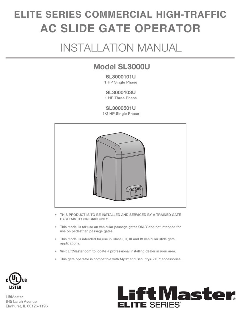
• THIS PRODUCT IS TO BE INSTALLED AND SERVICED BY A TRAINED GATE
SYSTEMS TECHNICIAN ONLY.
• This model is for use on vehicular passage gates ONLY and not intended for
use on pedestrian passage gates.
• This model is intended for use in Class I, II, III and IV vehicular slide gate
applications.
• Visit LiftMaster.com to locate a professional installing dealer in your area.
• This gate operator is compatible with MyQ®and Security+ 2.0™accessories.
ELITE SERIES COMMERCIAL HIGH-TRAFFIC
AC SLIDE GATE OPERATOR
INSTALLATION MANUAL
LiftMaster
845 Larch Avenue
Elmhurst, IL 60126-1196
SL3000101U
1 HP Single Phase
SL3000501U
1/2 HP Single Phase
Model SL3000U
OPERATOR
REQUIRES EXTERNAL
MONITORED ENTRAPMENT
PROTECTION DEVICE
TABLE OF CONTENTS
SAFETY 1
SAFETY SYMBOL AND SIGNAL WORD REVIEW ..................................1
USAGE CLASS .......................................................................................2
UL325 ENTRAPMENT PROTECTION REQUIREMENTS..........................2
SAFETY INSTALLATION INFORMATION ................................................3
GATE CONSTRUCTION INFORMATION..................................................4
INTRODUCTION 5
CARTON INVENTORY ............................................................................5
TOOLS NEEDED.....................................................................................5
OPERATOR SPECIFICATIONS................................................................6
SITE PREPARATION ..............................................................................7
OVERVIEW OF TYPICAL INSTALLATION...............................................8
INSTALLATION 9
TYPES OF INSTALLATIONS...................................................................9
INSTALLATION 10
DETERMINE LOCATION FOR CONCRETE PAD AND OPERATOR.........10
INSTALL THE OPERATOR....................................................................11
ATTACH THE CHAIN ............................................................................12
INSTALL ENTRAPMENT PROTECTION ................................................13
EARTH GROUND ROD .........................................................................15
POWER WIRING ..................................................................................15
DUAL GATES ONLY .............................................................................17
INSTALL THE COVER...........................................................................18
ADJUST THE HANDING AND LIMITS ..................................................19
OBSTRUCTION TEST ...........................................................................20
OPERATOR OVERVIEW 21
CONTROL BOARD OVERVIEW 22
CONTROL BOARD REFERENCE ...........................................................22
LEARN BUTTON...................................................................................23
DIAGNOSTIC DISPLAY ........................................................................23
HANDING BUTTONS ............................................................................23
BIPART DELAY ....................................................................................23
TIMER-TO-CLOSE (TTC) .....................................................................23
FORCE DIAL.........................................................................................24
TEST BUTTONS ...................................................................................24
STATUS LEDS......................................................................................24
WIRE ACCESSORIES TO CONTROL BOARD 25
THREE BUTTON CONTROL STATION ..................................................25
FIRE DEPARTMENT .............................................................................25
LOOPS .................................................................................................25
PHOTOELECTRIC SENSORS AND EDGE SENSORS.............................26
LOCKS .................................................................................................26
EXPANSION BOARD OVERVIEW 27
EXIT FAIL SWITCH...............................................................................27
AC FAIL SWITCH .................................................................................27
ANTI TAIL SWITCH..............................................................................27
QUICK CLOSE SWITCH........................................................................27
AUXILIARY RELAY 1 AND 2 ................................................................28
WIRE ACCESSORIES TO EXPANSION BOARD 29
PHOTOELECTRIC SENSORS AND EDGE SENSORS.............................29
CONTROL STATION.............................................................................29
LOOPS .................................................................................................30
ADDITIONAL WIRING 30
SAMS WIRING WITH RELAYS NOT ENERGIZED.................................30
FIELD WIRING .....................................................................................31
PROGRAMMING 32
REMOTE CONTROLS (NOT PROVIDED) ..............................................32
LIFTMASTER INTERNET GATEWAY (NOT PROVIDED) .......................33
ERASE ALL CODES..............................................................................33
TO REMOVE AND ERASE ALL MONITORED ENTRAPMENT PROTECTION
DEVICES ..............................................................................................33
SETTINGS 34
GATE OPERATOR SETUP EXAMPLES .................................................34
DUAL GATE SETTINGS ........................................................................35
MAINTENANCE 36
IMPORTANT SAFETY INFORMATION ..................................................36
MAINTENANCE ....................................................................................36
TROUBLESHOOTING 37
DIAGNOSTIC CODES ...........................................................................37
OPERATOR ALARM .............................................................................40
TROUBLESHOOTING CHART...............................................................41
ACCESSORIES 43
REPAIR PARTS 44
WARRANTY 45
1
SAFETY
MECHANICAL
ELECTRICAL
SAFETY SYMBOL AND SIGNAL WORD
REVIEW
When you see these Safety Symbols and Signal Words on the following
pages, they will alert you to the possibility of
Serious Injury or Death
if
you do not comply with the warnings that accompany them. The hazard
may come from something mechanical or from electric shock. Read the
warnings carefully.
When you see this Signal Word on the following pages, it will alert you
to the possibility of damage to your gate and/or the gate operator if you
do not comply with the cautionary statements that accompany it. Read
them carefully.
IMPORTANT NOTE:
• BEFORE attempting to install, operate or maintain the operator, you
must read and fully understand this manual and follow all safety
instructions.
• DO NOT attempt repair or service of your gate operator unless you
are an Authorized Service Technician.
2
USAGE CLASS
SAFETY
UL325 ENTRAPMENT PROTECTION REQUIREMENTS
CLASS I – RESIDENTIAL VEHICULAR GATE
OPERATOR
A vehicular gate operator (or system) intended for use in garages or
parking areas associated with a residence of one-to four single families.
CLASS II – COMMERCIAL/GENERAL ACCESS
VEHICULAR GATE OPERATOR
A vehicular gate operator (or system) intended for use in a commercial
location or building such as a multi-family housing unit (five or more
single family units), hotel, garages, retail store, or other buildings
accessible by or servicing the general public.
CLASS III – INDUSTRIAL/LIMITED ACCESS
VEHICULAR GATE OPERATOR
A vehicular gate operator (or system) intended for use in an industrial
location or building such as a factory or loading dock area or other
locations not accessible by or intended to service the general public.
CLASS IV– RESTRICTED ACCESS VEHICULAR GATE
OPERATOR
A vehicular gate operator (or system) intended for use in a guarded
industrial location or building such as an airport security area or other
restricted access locations not servicing the general public, in which
unauthorized access is prevented via supervision by security personnel.
IV
I
II
III
The same type of device shall not be used for both entrapment
protection means. Use of a single device to cover both the opening
and closing directions is in accordance with the requirement;
however, a single device is not required to cover both directions.
This operator is provided with Type A. The installer is required to
install additional entrapment protection devices in each entrapment
zone.
HORIZONTAL SLIDE AND SWING GATE OPERATOR
GATE OPERATOR ENTRAPMENT PROTECTION TYPES
Type A Inherent (built into the operator) entrapment
protection system
Type B1 Non-contact sensors such as photoelectric sensors
Type B2 Contact sensors such as edge sensors
This vehicular gate operator must be installed with at least two independent entrapment protection means as specified in the table below.
To reduce the risk of INJURY or DEATH:
• READ AND FOLLOW ALL INSTRUCTIONS.
• NEVER let children operate or play with gate controls. Keep the
remote control away from children.
• ALWAYS keep people and objects away from the gate. NO ONE
SHOULD CROSS THE PATH OF THE MOVING GATE.
• Test the gate operator monthly. The gate MUST reverse on contact
with a rigid object or reverse when an object activates the non-
contact sensors. After adjusting the force or the limit of travel,
retest the gate operator. Failure to adjust and retest the gate
operator properly can increase the risk of INJURY or DEATH.
• Use the emergency release ONLY when the gate is not moving.
• KEEP GATES PROPERLY MAINTAINED. Read the owner’s manual.
Have a qualified service person make repairs to gate hardware.
• The entrance is for vehicles ONLY. Pedestrians MUST use separate
entrance.
• SAVE THESE INSTRUCTIONS.
IMPORTANT SAFETY INFORMATION
3
SAFETY INSTALLATION INFORMATION
SAFETY
1. Vehicular gate systems provide convenience and security. Gate
systems are comprised of many component parts. The gate
operator is only one component. Each gate system is specifically
designed for an individual application.
2. Gate operating system designers, installers and users must take
into account the possible hazards associated with each individual
application. Improperly designed, installed or maintained systems
can create risks for the user as well as the bystander. Gate systems
design and installation must reduce public exposure to potential
hazards.
3. A gate operator can create high levels of force in its function as a
component part of a gate system. Therefore, safety features must
be incorporated into every design. Specific safety features include:
• Edges Sensors (contact) • Guards for Exposed Rollers
• Photoelectric Sensors • Screen Mesh
• Vertical Posts • Instructional and Precautionary Signage
4. Install the gate operator only when:
a. The operator is appropriate for the construction and the usage
class of the gate.
b. All openings of a horizontal slide gate are guarded or screened
from the bottom of the gate to a minimum of 6 feet (1.8 m)
above the ground to prevent a 2-1/4 inches (6 cm) diameter
sphere from passing through the openings anywhere in the gate,
and in that portion of the adjacent fence that the gate covers in
the open position.
c. All exposed pinch points are eliminated or guarded, and guarding
is supplied for exposed rollers.
5. The operator is intended for installation only on gates used for
vehicles. Pedestrians must be supplied with a separate access
opening. The pedestrian access opening shall be designed to
promote pedestrian usage. Locate the gate such that persons will
not come in contact with the vehicular gate during the entire path of
travel of the vehicular gate.
6. The gate must be installed in a location so that enough clearance is
supplied between the gate and adjacent structures when opening
and closing to reduce the risk of entrapment. Swinging gates shall
not open into public access areas.
7. The gate must be properly installed and work freely in both
directions prior to the installation of the gate operator.
8. Controls intended for user activation must be located at least 6 feet
(1.8 m) away from any moving part of the gate and where the user
is prevented from reaching over, under, around or through the gate
to operate the controls. Outdoor or easily accessible controls shall
have a security feature to prevent unauthorized use.
Exception: Emergency access controls only accessible by authorized
personnel (e.g. fire, police) may be placed at any location in the
line-of-sight of the gate.
9. The Stop and/or Reset (if provided separately) must be located in
the line-of-sight of the gate. Activation of the reset control shall not
cause the operator to start.
10. A minimum of two (2) WARNING SIGNS shall be installed, one on
each side of the gate where easily visible.
11. For a gate operator utilizing a non-contact sensor:
a. Reference owner’s manual regarding placement of non-contact
sensor for each type of application. See
Install Entrapment
Protection
section.
b. Care shall be exercised to reduce the risk of nuisance tripping,
such as when a vehicle trips the sensor while the gate is still
moving.
c. One or more non-contact sensors shall be located where the risk
of entrapment or obstruction exists, such as the perimeter
reachable by a moving gate or barrier.
12. For a gate operator utilizing a contact sensor such as an edge
sensor:
a. One or more contact sensors shall be located where the risk of
entrapment or obstruction exists, such as at the leading edge,
trailing edge and post mounted both inside and outside of a
vehicular horizontal slide gate.
b. A hard wired contact sensor shall be located and its wiring
arranged so the communication between the sensor and the gate
operator is not subject to mechanical damage.
c. A wireless device such as one that transmits radio frequency (RF)
signals to the gate operator for entrapment protection functions
shall be located where the transmission of the signals are not
obstructed or impeded by building structures, natural
landscaping or similar obstruction. A wireless device shall
function under the intended end-use conditions.
d. One or more contact sensors shall be located on the inside and
outside leading edge of a swing gate. Additionally, if the bottom
edge of a swing gate is greater than 6 inches (152 mm) above
the ground at any point in its arc of travel, one or more contact
sensors shall be located on the bottom edge.
e. One or more contact sensors shall be located at the bottom edge
of a vertical barrier (arm).

This manual suits for next models

3

Other Chamberlain Gate Opener manuals

Chamberlain B2202C User manual

Chamberlain

Chamberlain B2202C User manual

Chamberlain WGO200 User manual

Chamberlain

Chamberlain WGO200 User manual

Chamberlain 8747EML User manual

Chamberlain

Chamberlain 8747EML User manual

Chamberlain 050ACTWFATS User manual

Chamberlain

Chamberlain 050ACTWFATS User manual

Chamberlain Elite CSW200UL User manual

Chamberlain

Chamberlain Elite CSW200UL User manual

Chamberlain BG 3100-X1 User manual

Chamberlain

Chamberlain BG 3100-X1 User manual

Chamberlain SL400EVK User manual

Chamberlain

Chamberlain SL400EVK User manual

Chamberlain LA400EV User manual

Chamberlain

Chamberlain LA400EV User manual

Chamberlain 975 User manual

Chamberlain

Chamberlain 975 User manual

Chamberlain LiftMaster SUB300 User manual

Chamberlain

Chamberlain LiftMaster SUB300 User manual

Chamberlain LA400UL User manual

Chamberlain

Chamberlain LA400UL User manual

Chamberlain ELITE Series Quick start guide

Chamberlain

Chamberlain ELITE Series Quick start guide

Chamberlain LiftMaster Professional BG770 User manual

Chamberlain

Chamberlain LiftMaster Professional BG770 User manual

Chamberlain LiftMaster LM60 User manual

Chamberlain

Chamberlain LiftMaster LM60 User manual

Chamberlain HC250 User manual

Chamberlain

Chamberlain HC250 User manual

Chamberlain CSL24U User manual

Chamberlain

Chamberlain CSL24U User manual

Chamberlain GJ User manual

Chamberlain

Chamberlain GJ User manual

Chamberlain LA400 User manual

Chamberlain

Chamberlain LA400 User manual

Chamberlain LiftMaster PROFESSIONAL LYN300 Series User manual

Chamberlain

Chamberlain LiftMaster PROFESSIONAL LYN300 Series User manual

Chamberlain ART300 series User manual

Chamberlain

Chamberlain ART300 series User manual

Chamberlain SGO500 User manual

Chamberlain

Chamberlain SGO500 User manual

Chamberlain RSW12U User manual

Chamberlain

Chamberlain RSW12U User manual

Chamberlain Elite SL3000 User manual

Chamberlain

Chamberlain Elite SL3000 User manual

Chamberlain Smart Garage MYQ-G0401 User manual

Chamberlain

Chamberlain Smart Garage MYQ-G0401 User manual

Popular Gate Opener manuals by other brands

Nortek Security & Control Mighty Mule HD272 installation manual

Nortek Security & Control

Nortek Security & Control Mighty Mule HD272 installation manual

tousek TURN 10 Installation and operating instructions

tousek

tousek TURN 10 Installation and operating instructions

SOMFY AXOVIA 220B RTS installation instructions

SOMFY

SOMFY AXOVIA 220B RTS installation instructions

Nice HySecurity CBOX1050 Installation and programming manual

Nice HySecurity

Nice HySecurity CBOX1050 Installation and programming manual

CAME FROG-PM4 installation manual

CAME

CAME FROG-PM4 installation manual

Aprimatic ONDA 500 installation instructions

Aprimatic

Aprimatic ONDA 500 installation instructions

Turnstiles FSW 900 manual

Turnstiles

Turnstiles FSW 900 manual

Erreka BUL BL33 Quick installation and programming guide

Erreka

Erreka BUL BL33 Quick installation and programming guide

Extel VERA quick guide

Extel

Extel VERA quick guide

Beninca R1-2 WBV quick start guide

Beninca

Beninca R1-2 WBV quick start guide

Erreka VULCAN D user manual

Erreka

Erreka VULCAN D user manual

Motorline professional FORT User& installer's manual

Motorline professional

Motorline professional FORT User& installer's manual

Beninca BOB5024 manual

Beninca

Beninca BOB5024 manual

AGA GATEMASTER 900 HD installation manual

AGA

AGA GATEMASTER 900 HD installation manual

Cardin BL Series manual

Cardin

Cardin BL Series manual

Westfalia 85 27 06 instruction manual

Westfalia

Westfalia 85 27 06 instruction manual

Riello Elettronica CARDIN ACE FAST Instruction handbook

Riello Elettronica

Riello Elettronica CARDIN ACE FAST Instruction handbook

Telcoma ARM Instruction handbook

Telcoma

Telcoma ARM Instruction handbook

manuals.online logo
manuals.online logoBrands
  • About & Mission
  • Contact us
  • Privacy Policy
  • Terms and Conditions

Copyright 2025 Manuals.Online. All Rights Reserved.