manuals.online logo
Brands
  1. Home
  2. •
  3. Brands
  4. •
  5. CDVI
  6. •
  7. Receiver
  8. •
  9. CDVI SEL2641R433-IP User manual

CDVI SEL2641R433-IP User manual

Manufacturing Access Control since 1985
www.cdvi.ca
www.cdvi.ca
RECEIVER INTRODUCTION
The 2-relay stand-alone wireless receiver SEL2641R433-IP is a
superheterodyne single conversion receiver with integrated rolling-
code decoding. The receiver can control devices like; parking gates,
garage doors, multi-bay service centers, lighting, etc.
SPECIFICATIONS
Memorization: Up to 85 transmitter keys.
Self-learning and erasing of
the transmitter code without
accessing to the receiver board
Outputs: 2 (1NO, 1NO or NC)
Pulse, latched or timed
(from 1 sec. to 10 hours)
Operating frequency: 433 MHz
Power supply : 12 or 24 Vac/dc
Current consumption: 25 mA (relay activated: 55 mA)
Operating temperature: -20 to +70 °C
Dimensions: 105 x 45 x 28 mm
Weight: 65 g
2-Relay Wireless Receiver
SEL2641R433-IP
Instruction Manual
NO NCNO
Relay 1 Relay 2
1098
7
6
5
4
3
21
+
-
+
12V0V 24V
C C
PR
RVRR
LR
PV
LV
AC/DC
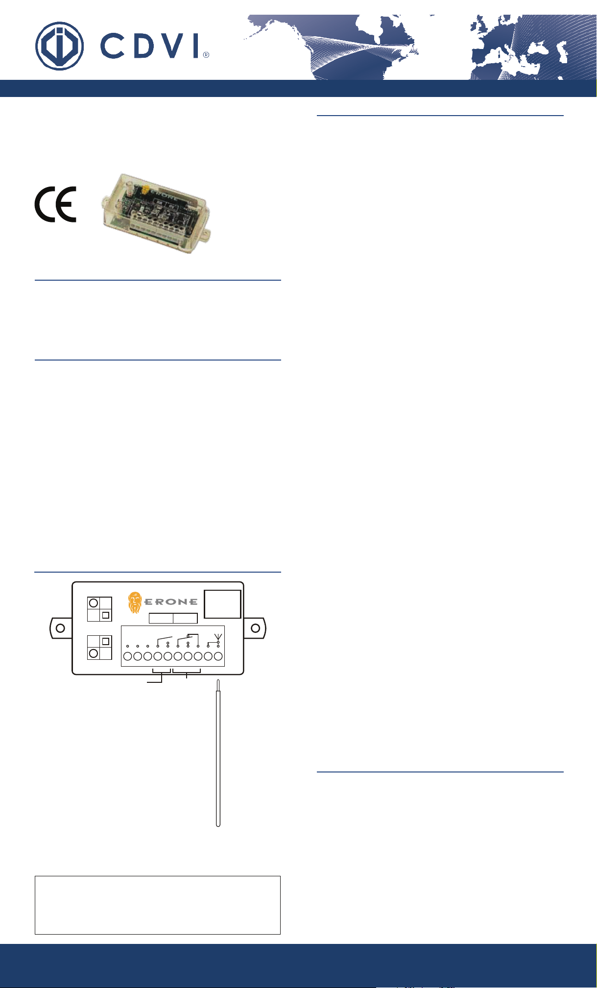
TERMINAL CONNECTIONS
LR: Red LED (RR: Relay 1)
LV: Green LED (RV: Relay 2)
PR: Push button for relay 1
PV: Push button for relay 2
1: 0V (GND)
2: 12 Vac/dc power supply
3: 24 Vac/dc power supply
4: Common relay 1 (RR)
5: N.O. relay 1 (RR)
6: Common relay 2 (RV)
7: N.O. relay 2 (RV)
8: N.C. relay 2(RV)
9: Antenna Shield
(used for SEA433 tuned antenna)
10: Antenna Core
Supplied
Antenna
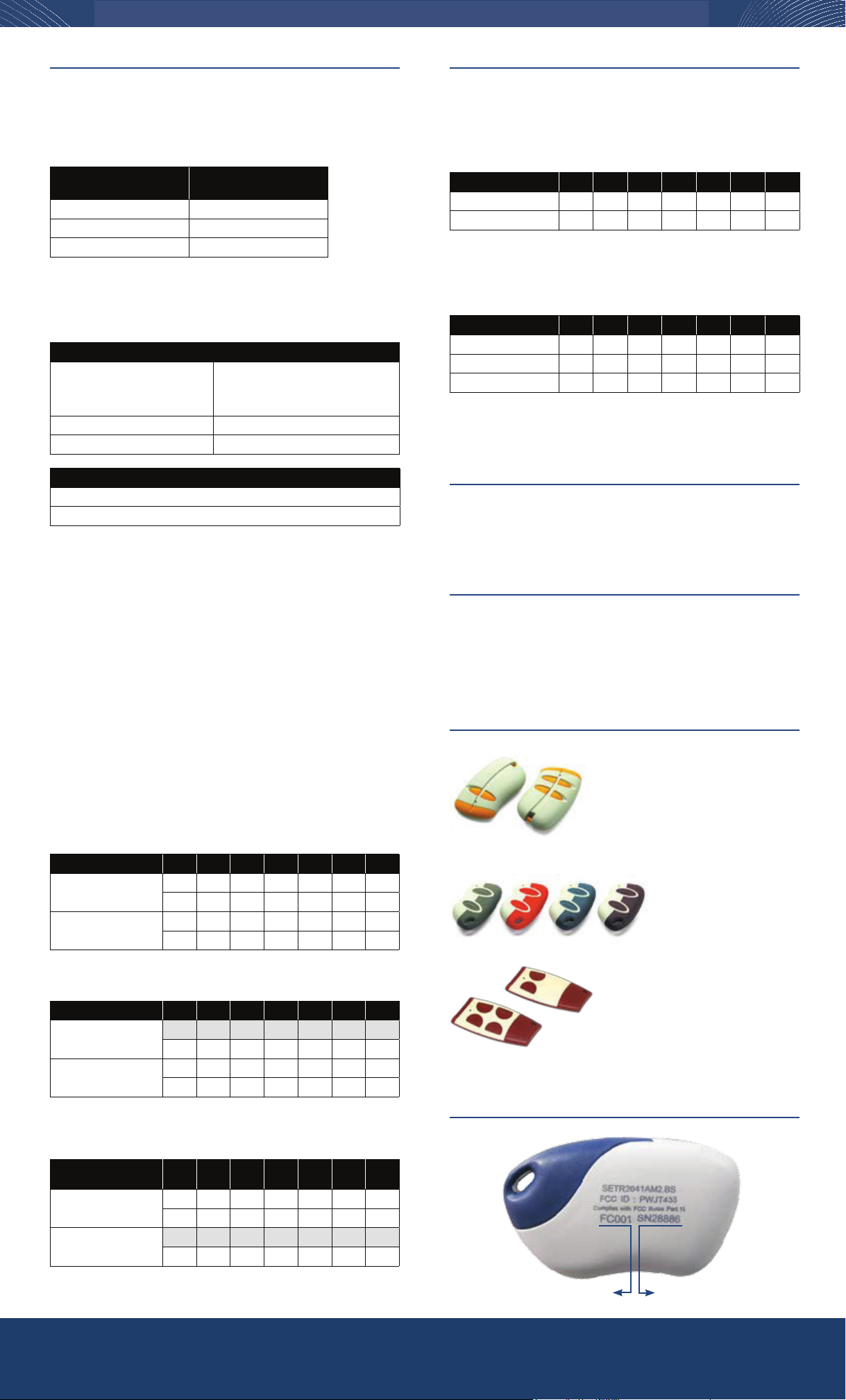
TRANSMITTER MEMORIZATION
Transmitter keys can be memorized in 2
different ways:
a) Locally, at the receiver, using PR or PV push-buttons.
b) Remotely, using transmitter keys.
a) Locally at the receiver
To activate Relay 1 (RR)
1) Press PR until LR LED turns ON, then release PR
2) Within 2 sec. press the key of the transmitter you want to
memorize. LR LED will ash and relay 1 (RR) will activate for a
while.
3) Press the key of the transmitter again to verify relay 1 (RR) activa-
tion, LR LED will turn ON and LV LED will ash.
At each activation, and for all the transmission time, LR LED will
turn on , LV LED will ash and relay 1 (RR) remains activated.
To activate Relay 2 (RV)
1) Press PV until LV LED turns ON, then release PV
2) Within 2 sec. press the key of the transmitter you want to
memorize. LV LED will ash and the relay 2 (RV) will activate for
a while.
3) Press the key of the transmitter again to verify relay 2 activation,
LR LED will turn ON and LV LED will ash.
At each activation, and for all the transmission time, LV LED will
turn on , LR LED will ash and relay 2 (RV) remains activated.
b) Remotely
Note: One transmitter (two keys) have to be programmed locally to be
able to programmed other transmitter keys remotely.
1) Press both keys of the transmitter that is already stored in the
receiver until the receiver “beeps”;
2) Release both keys and immediatlely press A or B key to select
the corresponding relay to be programmed and hold key for 4
seconds. Relay LED will turn on and “beep” will be continuous
3) Within 2 sec., press the new transmitter key to be memorized.
Example:
Transmitter 1 (TX1) already stored, transmitter 2 (TX2), key A= Realy 1
(RR) and key B= Realy 2 (RV)
Press keys A & B of TX1 (bip); Press key A of TX1 for 4
sec.(Biiiiiiiip); Press key A of TX2 within 2 sec.
Press keys A & B of TX1 (bip); Press key B of TX1 for 4
sec.(Biiiiiiiip); push key B of TX2 within 2 sec.
NOTE : Memory capacity is 85 transmitter keys. A 4-keys transmitter
needs 4 memory positions, if all 4 keys are used. The receiver memory
is full when, at the end of step 2 of transmitter memorization, LV and
LR LED ash 3 times. A transmitter key can not activate both relay (RR
and RV).
TRANSMITTER KEY OVERWRITE
NOTE : Before starting, obtain the memory position and relay
activation (1 or 2) of the transmitter key you wish to overwrite. See
“Memory Psition” section.
1) Press down PR or PV for 4 sec. until the corresponding LED
remains lit, then release it.
2) Within 2 sec., press down PV for 1 sec. (LED will turn off)
3) Within 2 sec., start to enter the memory position sequence by
using PR (red LED) and PV (green LED). See memory position
table.
4) At the end of the sequence LV or LR LED will turn on.
5) Within 4 sec., press the key of the new transmitter you wish to
memorized. This new transmitter key will overwrite the old one.
WARRANTY
The warranty period for this product is 24 months, beginning from the manufacturer date.
During this period, if the product does not work correctly, due to a defective component,
the product will be repaired or substituted at our discretion. The guarantee does not cover
the plastic container integrity. After-sale service is supplied at the factory.
For more information, please visit www.devancocanada.com or call toll free at 855-931-3334
Manufacturing Access Control since 1985
CDVI® 1645-A Highway 440 West, Laval, Québec, Canada, H7L3W3
Tel: (450) 682-7945, Toll Free Tel: 1-866-610-0102, Fax: (450) 682-9590, Toll Free Fax: 1-866-682-9590
SEL2641R433-IP_IE - Specications may change without prior notice. Printed in Canada - 15/11/07
MEMORy pOSITION
1) Press transmitter key to verify if its associated to the receiver. LR
or LV will turn ON and the related relay will activate.
2) Press and hold PR for 1 sec. and then release it. A sequence
of 7 ashes of the LEDs (LR and LV) starts. Note the LED color
sequence. Refer to the following table to decode the sequence.
Flash sequence 1 2 3 4 5 6 7
LV (green LED) 1 2 4 8 16 32 64
LR (red LED) 0 0 0 0 0 0 0
LR=0 all the time.
Add the value of LV (where it ashes in the sequence) to obtain the
memory position. See example below.
Example 1:
Flash sequence 1 2 3 4 5 6 7
LV (green LED) - - Flash Flash ---
LR (red LED) Flash Flash - - Flash Flash Flash
Sequence Value 0 0 4 8 0 0 0
Memory position= 0 + 0 + 4 + 8 + 0 + 0 + 0= 12
The transmitter key is located at memory position #12.
ENROLLED TRaNSMITTER kEyS
1) Press down PV for 1 sec. LR and LV LED starts a sequence of 7
ashes. Note the color sequence and refer to the above table to
obtain the number of enrolled transmitter keys.
MEMORy RESET (faCTORy DEfaULT)
1) Press PR until LR LED turns on.
2) Release PR and within 1 sec. press PR and PV simultaneously
until LR and LV LED starts to ash 3 times (about 4 sec.)
At this point all settings are erased and the receiver is reset to factory
default.
RELay CONfIgURaTION
RELAY STATUS:
Note: The receiver factory default setting is pulse for both relay
Press down PR or PV for 4 sec. and note the LED state (LR or LV).
The following table determine the relay status :
Relay operating mode
( RR or RV )
LED operating mode
( LR or LV )
Pulse LED ON
Latched (RR only) Slow blinking
Timed Fast blinking
RELAY SETTING:
The relay operating mode is cyclic, change the mode according to the
following rules:
Relay operating mode cycle
If the relay is set as pulse 1- it becomes latching
2- it becomes timed if you press
the timing sequence after step 2
If the relay is set as latching it becomes pulse
If the relay is set as timed it becomes pulse
Relay Conguration Not Allowed
Relay 1 (RR) latching and Relay 2 (RV) timed
Relay 1 (RR) timed and relay 2 (RV) timed (with different delay time)
To change the mode follow these steps:
1) Press PV or PR for 4 seconds. LED will illuminate displaying relay
status. Use Table above to determine the status.
2) Within 1 sec., press PR to change the relay mode. The relay
mode will change according to the relay setting table above.
Note: To congure the relay output time, enter the timing sequence
after step 2, see relay timing table below.
RELAY TIMING:
Important: To set or modify relay timing, the relay has to be set as
pulse before.
1) Press PR for 4 sec. The LR LED will turn ON (if not, set the relay
operation to pulse, see Relay Setting section).
2) Press PR for 1 sec. and LR LED switche to OFF. Within 2
seconds, start the seven digit, PR and PV sequence, to set the
relay timing (See table below)
PR= not seclected (0) PV= selected (1)
Pressing sequence 1 2 3 4 5 6 7
Seconds 1 2 4 8 16 PR PR
10 20 40 80 160 PV PR
Minutes 2 4 8 16 32 PR PV
20 40 80 160 320 PV PV
Example 1: 8 sec. relay activation
Pressing sequence 1 2 3 4 5 6 7
Seconds PR PR PR PV PR PR PR
10 20 40 80 160 PV PR
Minutes 2 4 8 16 32 PR PV
20 40 80 160 320 PV PV
Input sequence= PR + PR + PR + PV + PR + PR + PR= 8 sec.
Example 2: 2 min. relay activation
PR and PV
pressing sequence 1234567
Seconds 1 2 4 8 16 PR PR
10 20 40 80 160 PV PR
Minutes PV PR PR PR PR PR PV
20 40 80 160 320 PV PV
Input sequence= PV - PR - PR - PR - PR - PR - PV= 2 min.
Facility code (FC)= 001 Serial Number (SN)= 28886
COMpaTIbLE TRaNSMITTERS
2-Channel Mini Transmitters
Red: SETR2641AM2R
Blue: SETR2641AM2B
Burgundy: SETR2641AM2C
Dark Gray: SETR2641AM2N
2-Channel Transmitters
S2TR2641E2
Available with built-in
proximity badge
S2TR2641E2H
4-Channel Transmitters
S2TR2641E4
2-Channel
Ultra-Thin Transmitters
S5TR2641E2S
4-Channel
Ultra-Thin Transmitters
S5TR2641E4S
Available with optional
built-in proximity badge
faCILITy CODE aND SERIaL NUMbER LOCaTION
For more information, please visit www.devancocanada.com or call toll free at 855-931-3334
# FC Code Serial # Key Button Relay User Name
1A� B� C� D� 1 � 2�
2A� B� C� D� 1 � 2�
3A� B� C� D� 1 � 2�
4A� B� C� D� 1 � 2�
5A� B� C� D� 1 � 2�
6A� B� C� D� 1 � 2�
7A� B� C� D� 1 � 2�
8A� B� C� D� 1 � 2�
9A� B� C� D� 1 � 2�
10 A� B� C� D� 1 � 2�
11 A� B� C� D� 1 � 2�
12 A� B� C� D� 1 � 2�
13 A� B� C� D� 1 � 2�
14 A� B� C� D� 1 � 2�
15 A� B� C� D� 1 � 2�
16 A� B� C� D� 1 � 2�
17 A� B� C� D� 1 � 2�
18 A� B� C� D� 1 � 2�
19 A� B� C� D� 1 � 2�
20 A� B� C� D� 1 � 2�
21 A� B� C� D� 1 � 2�
22 A� B� C� D� 1 � 2�
23 A� B� C� D� 1 � 2�
24 A� B� C� D� 1 � 2�
25 A� B� C� D� 1 � 2�
26 A� B� C� D� 1 � 2�
27 A� B� C� D� 1 � 2�
28 A� B� C� D� 1 � 2�
29 A� B� C� D� 1 � 2�
30 A� B� C� D� 1 � 2�
31 A� B� C� D� 1 � 2�
32 A� B� C� D� 1 � 2�
33 A� B� C� D� 1 � 2�
34 A� B� C� D� 1 � 2�
35 A� B� C� D� 1 � 2�
36 A� B� C� D� 1 � 2�
37 A� B� C� D� 1 � 2�
38 A� B� C� D� 1 � 2�
39 A� B� C� D� 1 � 2�
40 A� B� C� D� 1 � 2�
41 A� B� C� D� 1 � 2�
42 A� B� C� D� 1 � 2�
Relay 1 (Red LED):_____________________________
Relay 2 (Green LED):___________________________
# FC Code Serial # Key Button Relay User Name
43 A� B� C� D� 1 � 2�
44 A� B� C� D� 1 � 2�
45 A� B� C� D� 1 � 2�
46 A� B� C� D� 1 � 2�
47 A� B� C� D� 1 � 2�
48 A� B� C� D� 1 � 2�
49 A� B� C� D� 1 � 2�
50 A� B� C� D� 1 � 2�
51 A� B� C� D� 1 � 2�
52 A� B� C� D� 1 � 2�
53 A� B� C� D� 1 � 2�
54 A� B� C� D� 1 � 2�
55 A� B� C� D� 1 � 2�
56 A� B� C� D� 1 � 2�
57 A� B� C� D� 1 � 2�
58 A� B� C� D� 1 � 2�
59 A� B� C� D� 1 � 2�
60 A� B� C� D� 1 � 2�
61 A� B� C� D� 1 � 2�
62 A� B� C� D� 1 � 2�
63 A� B� C� D� 1 � 2�
64 A� B� C� D� 1 � 2�
65 A� B� C� D� 1 � 2�
66 A� B� C� D� 1 � 2�
67 A� B� C� D� 1 � 2�
68 A� B� C� D� 1 � 2�
69 A� B� C� D� 1 � 2�
70 A� B� C� D� 1 � 2�
71 A� B� C� D� 1 � 2�
72 A� B� C� D� 1 � 2�
73 A� B� C� D� 1 � 2�
74 A� B� C� D� 1 � 2�
75 A� B� C� D� 1 � 2�
76 A� B� C� D� 1 � 2�
77 A� B� C� D� 1 � 2�
78 A� B� C� D� 1 � 2�
79 A� B� C� D� 1 � 2�
80 A� B� C� D� 1 � 2�
81 A� B� C� D� 1 � 2�
82 A� B� C� D� 1 � 2�
83 A� B� C� D� 1 � 2�
84 A� B� C� D� 1 � 2�
85 A� B� C� D� 1 � 2�
HOW TO ORDER REPAIR PARTS
DEVANCO CANADA
19192 HAY ROAD, UNIT Q
SUMMERSTOWN, ON K0C 2E0
TOLL FREE: 855-931-3334
www.devancocanada.com
WHEN ORDERING REPAIR PARTS
PLEASE SUPPLY THE FOLLOWING INFORMATION:
3PART NUMBER
3DESCRIPTION
3MODEL NUMBER

This manual suits for next models

1

Other CDVI Receiver manuals

CDVI RADIUM WRW User manual

CDVI

CDVI RADIUM WRW User manual

CDVI ERONE SELWR433 User manual

CDVI

CDVI ERONE SELWR433 User manual

CDVI SEL2641R433-XPL5 User manual

CDVI

CDVI SEL2641R433-XPL5 User manual

CDVI SEL2641R433-XPL2P User manual

CDVI

CDVI SEL2641R433-XPL2P User manual

CDVI SELWR433-SAT User manual

CDVI

CDVI SELWR433-SAT User manual

CDVI SEL2641R433-XPL User manual

CDVI

CDVI SEL2641R433-XPL User manual

CDVI ERONE SEL2641R433-XPL4V User manual

CDVI

CDVI ERONE SEL2641R433-XPL4V User manual

CDVI Digitag LR DTRR1434R User manual

CDVI

CDVI Digitag LR DTRR1434R User manual

CDVI SEL2641R433-XPL4P User manual

CDVI

CDVI SEL2641R433-XPL4P User manual

CDVI DIGITAG-LR User manual

CDVI

CDVI DIGITAG-LR User manual

CDVI SEL128R433-WPL User guide

CDVI

CDVI SEL128R433-WPL User guide

CDVI RX26-XPL5-GFA User manual

CDVI

CDVI RX26-XPL5-GFA User manual

CDVI DIGITAG-LR DTRR1434R User manual

CDVI

CDVI DIGITAG-LR DTRR1434R User manual

CDVI ERONE SEL2641R433-XPL1V User manual

CDVI

CDVI ERONE SEL2641R433-XPL1V User manual

CDVI SEL2641R433-XPL User manual

CDVI

CDVI SEL2641R433-XPL User manual

CDVI SEL2641R433-XPL2V User manual

CDVI

CDVI SEL2641R433-XPL2V User manual

Popular Receiver manuals by other brands

Pioneer AVH-P4490BT owner's manual

Pioneer

Pioneer AVH-P4490BT owner's manual

Sunricher SR-1009DIN quick start guide

Sunricher

Sunricher SR-1009DIN quick start guide

Chamberlain LiftMaster 312HMC quick start guide

Chamberlain

Chamberlain LiftMaster 312HMC quick start guide

Magenta Research MultiView AK500 Quick reference & setup guide

Magenta Research

Magenta Research MultiView AK500 Quick reference & setup guide

innoXplore iX-B36 user manual

innoXplore

innoXplore iX-B36 user manual

Sony ICF-25 Service manual

Sony

Sony ICF-25 Service manual

Delkim Rx Plus Pro operating instructions

Delkim

Delkim Rx Plus Pro operating instructions

Hama Nano 00053330 Operating	 instruction

Hama

Hama Nano 00053330 Operating instruction

CHC i80 GNSS quick start guide

CHC

CHC i80 GNSS quick start guide

Yamaha RP-U100 owner's manual

Yamaha

Yamaha RP-U100 owner's manual

Dension DBU-9203-3 General user guide

Dension

Dension DBU-9203-3 General user guide

Optimus 12-174 owner's manual

Optimus

Optimus 12-174 owner's manual

Futurecom MOBEXCOM DVE user manual

Futurecom

Futurecom MOBEXCOM DVE user manual

Eagle Multi Satellite S-4180-GX+ Specification sheet

Eagle

Eagle Multi Satellite S-4180-GX+ Specification sheet

R&S FSMR operating manual

R&S

R&S FSMR operating manual

Kenwood KDC-BT73DAB instruction manual

Kenwood

Kenwood KDC-BT73DAB instruction manual

Samsung SADPCI-202 instruction manual

Samsung

Samsung SADPCI-202 instruction manual

Sony STR-DA2ES - Fm Stereo/fm-am Receiver Product information

Sony

Sony STR-DA2ES - Fm Stereo/fm-am Receiver Product information

manuals.online logo
manuals.online logoBrands
  • About & Mission
  • Contact us
  • Privacy Policy
  • Terms and Conditions

Copyright 2025 Manuals.Online. All Rights Reserved.