Charge Xpress CXC-6525A User manual
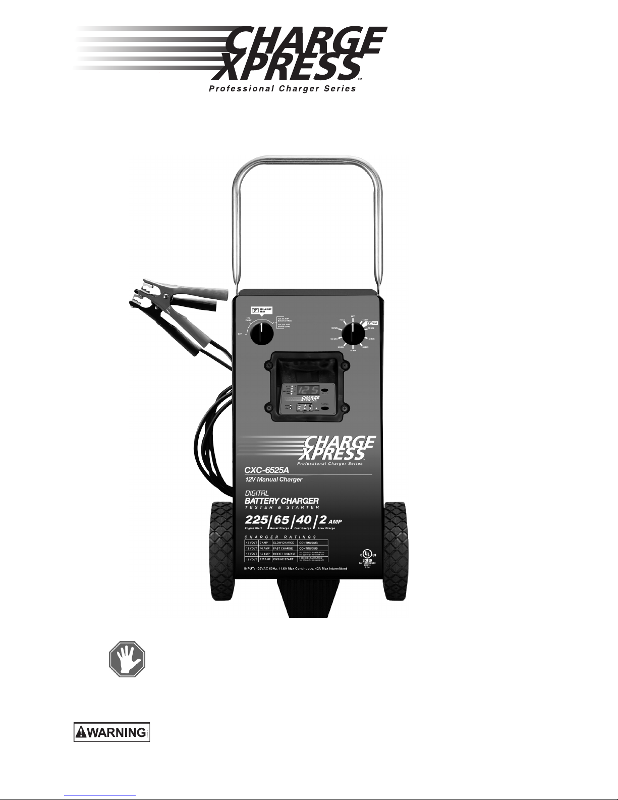
Model: CXC-6525A
Digital Battery Charger
0099001326-00
READ THE ENTIRE MANUAL BEFORE USING THIS PRODUCT.
FAILURE TO DO SO COULD RESULT IN SERIOUS INJURY OR DEATH.
OWNERS
MANUAL
DO NOT RETURN THIS PRODUCT TO THE STORE!
Contact Customer Service for assistance:
Phone: 800-621-5485
Web: www.batterychargers.com
Voltage: 12
Amperage: 2, 40, 65

•2 •
IMPORTANT: READ AND SAVE THIS SAFETY AND INSTRUCTION MANUAL.
SAVE THESE INSTRUCTIONS – This manual will show you how to use your charger
safely and effectively. Please read, understand and follow these instructions and precau-
tions carefully, as this manual contains important safety and operating instructions. The
safety messages used throughout this manual contain a signal word. The signal word
indicates the level of the hazard in a situation.
Indicates an imminently hazardous situation which, if not avoided, will result in
death or serious injury to the operator or bystanders.
Indicates a potentially hazardous situation which, if not avoided, could result in
death or serious injury to the operator or bystanders.
Indicates a potentially hazardous situation which, if not avoided, could result in
moderate or minor injury to the operator or bystanders.
Indicates a potentially hazardous situation which, if not avoided, could result in
damage to the equipment, vehicle or property.
Pursuant to California Proposition 65, this product contains chemicals known to
the State of California to cause cancer and birth defects or other reproductive
harm. Wash hands after handling.
1. IMPORTANT SAFETY INSTRUCTIONS – SAVE THESE INSTRUCTIONS.
This manual contains important safety and operating instructions.
RISK OF ELECTRIC SHOCK OR FIRE.
1.1 Keep out of reach of children.
1.2 Do not expose the charger to rain or snow.
1.3 Use only recommended attachments. Use of an attachment
not recommended or sold by Schumacher®Electric Corporation
may result in a risk of re, electric shock or injury to persons or damage to property.
1.4 To reduce the risk of damage to the electric plug or cord, pull by the plug rather than the
cord when disconnecting the charger.
1.5 An extension cord should not be used unless absolutely necessary. Use of an improper
extension cord could result in a risk of re and electric shock. If an extension cord must be
used, make sure:
• That the pins on the plug of the extension cord are the same number, size and shape as
those of the plug on the charger.
• That the extension cord is properly wired and in good electrical condition.
• That the wire size is large enough for the AC ampere rating of the charger as specied
in section 8.
1.6 To reduce the risk of electric shock, unplug the charger from the outlet before attempting
any maintenance or cleaning. Simply turning off the controls will not reduce this risk.
1.7 Do not operate the charger with a damaged cord or plug; have the cord or plug replaced
immediately by a qualied service person.
1.8 Do not operate the charger if it has received a sharp blow, been dropped or otherwise
damaged in any way; take it to a qualied service person.
1.9 Do not disassemble the charger; take it to a qualied service person when service or repair
is required. Incorrect reassembly may result in a risk of re or electric shock.
RISK OF EXPLOSIVE GASES.
1.10 WORKING IN THE VICINITY OF A LEAD-ACID BATTERY IS
DANGEROUS. BATTERIES GENERATE EXPLOSIVE GASES DURING
NORMAL BATTERY OPERATION. FOR THIS REASON, IT IS OF UTMOST
IMPORTANCE THAT YOU FOLLOW THE INSTRUCTIONS EACH TIME YOU
USE THE CHARGER.
1.11 To reduce the risk of a battery explosion, follow these instructions and those published by
the battery manufacturer and the manufacturer of any equipment you intend to use in the
vicinity of the battery. Review the cautionary markings on these products and on the engine.

•3 •
2. PERSONAL PRECAUTIONS
RISK OF EXPLOSIVE GASES.
2.1 NEVER smoke or allow a spark or ame in the vicinity of a battery or
engine.
2.2 Remove personal metal items such as rings, bracelets, necklaces and
watches when working with a lead-acid battery. A lead-acid battery can produce
a short-circuit current high enough to weld a ring or the like to metal, causing a
severe burn.
2.3 Be extra cautious, to reduce the risk of dropping a metal tool onto the battery. It might
spark or short-circuit the battery or other electrical part that may cause an explosion.
2.4 Use this charger for charging 12V LEAD-ACID batteries only. It is not intended to supply
power to a low voltage electrical system other than in a starter-motor application. Do not
use this battery charger for charging dry-cell batteries that are commonly used with home
appliances. These batteries may burst and cause injury to persons and damage to property.
2.5 NEVER charge a frozen battery.
2.6 NEVER overcharge a battery.
2.7 Consider having someone nearby to come to your aid when you work near a lead-acid battery.
2.8 Have plenty of fresh water and soap nearby in case battery acid contacts your skin,
clothing or eyes.
2.9 Wear complete eye and body protection, including safety goggles and protective clothing.
Avoid touching your eyes while working near the battery.
2.10 If battery acid contacts your skin or clothing, immediately wash the area with soap and
water. If acid enters your eye, immediately ood the eye with cold running water for at
least 10 minutes and get medical attention right away.
2.11 If battery acid is accidentally swallowed, drink milk, the whites of eggs or water. DO NOT
induce vomiting. Seek medical attention immediately.
3. PREPARING TO CHARGE
RISK OF CONTACT WITH BATTERY ACID. BATTERY ACID IS A
HIGHLY CORROSIVE SULFURIC ACID.
3.1 If it is necessary to remove the battery from the vehicle to
charge it, always remove the grounded terminal rst. Make sure all
of the accessories in the vehicle are off, to prevent arcing.
3.2 Be sure the area around the battery is well ventilated while
the battery is being charged.
3.3 Clean the battery terminals before charging the battery. During cleaning, keep airborne
corrosion from coming into contact with your eyes, nose and mouth. Use baking soda and
water to neutralize the battery acid and help eliminate airborne corrosion. Do not touch
your eyes, nose or mouth.
3.4 Add distilled water to each cell until the battery acid reaches the level specied by the
battery manufacturer. Do not overll. For a battery without removable cell caps, such as
valve regulated lead-acid batteries (VRLA), carefully follow the manufacturer’s recharging
instructions.
3.5 Read, understand and follow all instructions for the charger, battery, vehicle and any
equipment used near the battery and charger. Study all of the battery manufacturer’s
specic precautions while charging and recommended rates of charge.
3.6 Determine the voltage of the battery by referring to the vehicle owner’s manual.
3.7 Make sure that the charger cable clips make tight connections.

•4 •
4. CHARGER LOCATION
RISK OF EXPLOSION AND CONTACT
WITH BATTERY ACID.
4.1 Locate the charger as far away from the
battery as the DC cables permit.
4.2 Never place the charger directly above the
battery being charged; gases from the battery will
corrode and damage the charger.
4.3 Do not set the battery on top of the charger.
4.4 Never allow battery acid to drip onto the charger when reading the electrolyte specic
gravity or lling the battery.
4.5 Do not operate the charger in a closed-in area or restrict the ventilation in any way.
5. DC CONNECTION PRECAUTIONS
5.1 Connect and disconnect the DC output clips only after setting all of the charger switches
to the “off” position and removing the AC plug from the electrical outlet. Never allow the
clips to touch each other.
5.2 Attach the clips to the battery and chassis, as indicated in sections 6 and 7.
6. FOLLOW THESE STEPS WHEN BATTERY IS INSTALLED IN VEHICLE
A SPARK NEAR THE BATTERY MAY CAUSE A
BATTERY EXPLOSION. TO REDUCE THE RISK
OF A SPARK NEAR THE BATTERY:
6.1 Position the AC and DC cables to reduce the
risk of damage by the hood, door and moving or hot
engine parts. NOTE: If it is necessary to close the
hood during the charging process, ensure that the hood does not touch the metal part of
the battery clips or cut the insulation of the cables.
6.2 Stay clear of fan blades, belts, pulleys and other parts that can cause injury.
6.3 Check the polarity of the battery posts. The POSITIVE (POS, P, +) battery post usually
has a larger diameter than the NEGATIVE (NEG, N, -) post.
6.4 Determine which post of the battery is grounded (connected) to the chassis. If the
negative post is grounded to the chassis (as in most vehicles), see step 6.5. If the positive
post is grounded to the chassis, see step 6.6.
6.5 For a negative-grounded vehicle, connect the POSITIVE (RED) clip from the battery
charger to the POSITIVE (POS, P, +) ungrounded post of the battery. Connect the
NEGATIVE (BLACK) clip to the vehicle chassis or engine block away from the battery. Do
not connect the clip to the carburetor, fuel lines or sheet-metal body parts. Connect to a
heavy gauge metal part of the frame or engine block.
6.6 For a positive-grounded vehicle, connect the NEGATIVE (BLACK) clip from the battery
charger to the NEGATIVE (NEG, N, -) ungrounded post of the battery. Connect the
POSITIVE (RED) clip to the vehicle chassis or engine block away from the battery. Do not
connect the clip to the carburetor, fuel lines or sheet-metal body parts. Connect to a heavy
gauge metal part of the frame or engine block.
6.7 Connect charger AC supply cord to electrical outlet.
6.8 When disconnecting the charger, turn all switches to off, disconnect the AC cord, remove
the clip from the vehicle chassis and then remove the clip from the battery terminal.
6.9 See CALCULATING CHARGE TIME for length of charge information.
7. FOLLOW THESE STEPS WHEN BATTERY IS OUTSIDE VEHICLE
A SPARK NEAR THE BATTERY MAY CAUSE A
BATTERY EXPLOSION. TO REDUCE THE RISK
OF A SPARK NEAR THE BATTERY:
7.1 Check the polarity of the battery posts. The
POSITIVE (POS, P, +) battery post usually has a
larger diameter than the NEGATIVE (NEG, N, -) post.
7.2 Attach at least a 24-inch (61 cm) long 6-gauge (AWG) insulated battery cable to the
NEGATIVE (NEG, N, -) battery post.

•5 •
7.3 Connect the POSITIVE (RED) charger clip to the POSITIVE (POS, P, +) post of the battery.
7.4 Position yourself and the free end of the cable you previously attached to the NEGATIVE
(NEG, N, -) battery post as far away from the battery as possible – then connect the
NEGATIVE (BLACK) charger clip to the free end of the cable.
7.5 Do not face the battery when making the nal connection.
7.6 Connect charger AC supply cord to electrical outlet.
7.7 When disconnecting the charger, always do so in the reverse order of the connecting
procedure and break the rst connection while as far away from the battery as practical.
7.8 A marine (boat) battery must be removed and charged on shore. To charge it onboard
requires equipment specially designed for marine use.
8. GROUNDING AND AC POWER CORD CONNECTIONS
RISK OF ELECTRIC SHOCK OR FIRE.
8.1 This battery charger is for use on a nominal 120 volt circuit
and has a grounded plug. The charger must be grounded to
reduce the risk of electric shock. The plug must be plugged into an
outlet that is properly installed and grounded in accordance with all
local codes and ordinances. The plug pins must t the receptacle
(outlet). Do not use with an ungrounded system.
8.2 Never alter the AC cord or plug provided – if it does not t the outlet,
have a proper grounded outlet installed by a qualied electrician. An improper connection
can result in a risk of an electric shock or electrocution. NOTE: The use of an adapter
plug is not recommended and should not be used.
8.3 Recommended minimum AWG size for extension cord:
• 100 feet (30.5 meters) long or less – use a 10 gauge (6 mm2) extension cord.
• Over 100 feet (30.5 meters) long – use an 8 gauge (10 mm2) extension cord.
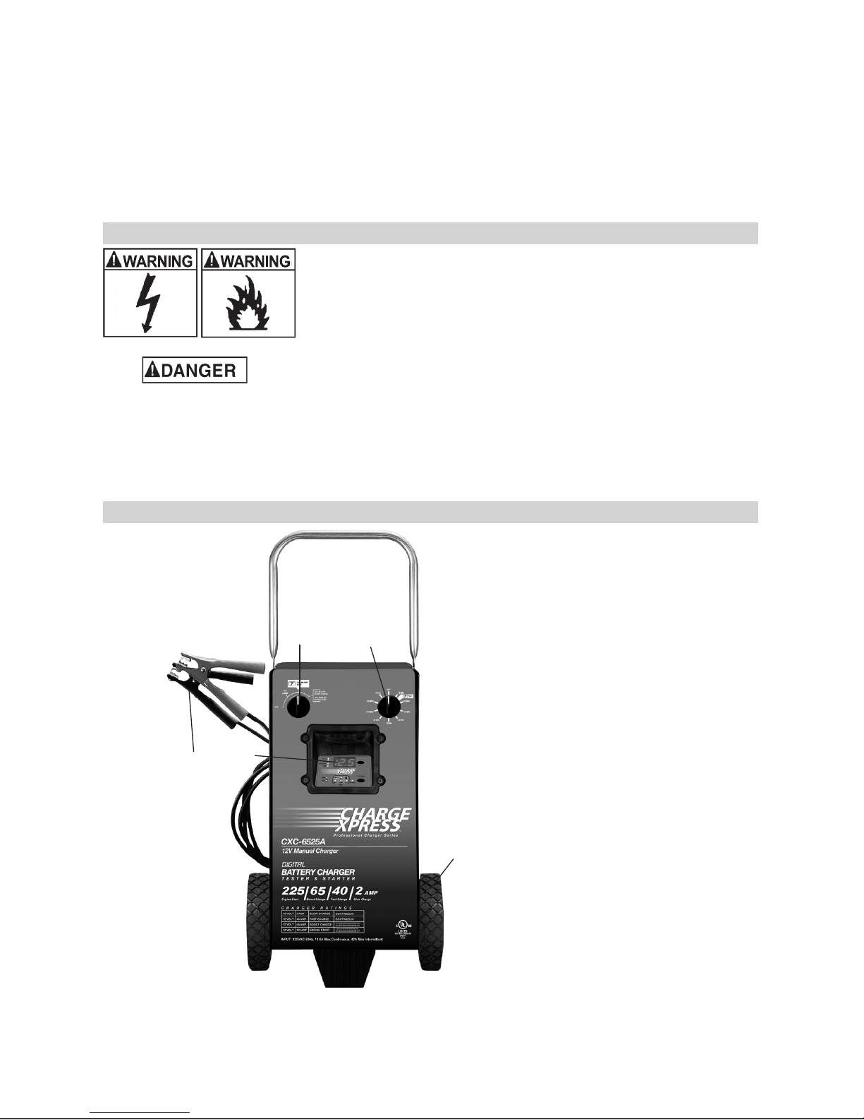
9. FEATURES
12
3
4
5
1. Charge Rate Selector Switch
2. Timer
3. Control Panel with Digital Display
4. Battery Clips
5. Wheel

•6 •
10. ASSEMBLY INSTRUCTIONS
It is important to fully assemble your charger before use. Follow these
instructions for assembly.
Attach the Handle:
1. Turn the charger right side up onto its foot and wheels.
2. Using a ¼ inch nut driver or socket, remove the two top rear screws
from each side of the charger.
3. Align the handle so that the screw holes are aligned with the screw
holes on each side of the charger making sure that the handle is
ush with the back edge of the charger. (Notice offset of holes to
orient the handle correctly.)
4. Attach the handle using the same screws you previously removed.
11. CONTROL PANEL
START
BAT. A LT. CHARGE
0899006127
AMP-HRS.
TIME 12
1
2
3
4
5
6
7
8
9
10
11
V
A
Ah
TEST
PASS
FAIL
Timer
• Timer Setting: The timer allows you to set a specied
time for charging, after the timer expires the charger stops
charging your battery. The main function of the timer is
to prevent over charging while allowing a battery time
to obtain a satisfactory charge. To properly set the timer
you must know the size of the battery in ampere hours
or reserve capacity in minutes and the state of charge. It
is important that you determine the appropriate state of
charge of your battery as specied in Section 13 and set
the timer accordingly.
• Hold: This position defeats the timer function, allowing for continuous operation.
Digital Display
The Digital Display gives a digital indication of voltage, % of charge or time, depending on
the Display Mode chosen.
Select Button
Use this button to set the function of the digital display to one of the following:
• Volts – The digital display shows the voltage at the charger battery clips in DC volts.
• Amps – The digital display shows the amount of current, measured in amps, that is
being drawn by the battery.
• Amp hours – The display shows the accumulated Amp hours during a test.
• Time – During timer operations, the display shows elapsed time.

•7 •
Function Button
This button allows users to change the operation from Charging to Test Modes (Battery
Charge Acceptance, Starter, or Alternator Test).
Pass/Fail LEDs – A green LED indicates Pass; a red LED indicates Fail.
Charge Rate Selector Switch
Use the Charge Rate selector switch to select the charge rate or engine starting setting
you require.
• 2A Slow Charge Rate – Intended for charging small
batteries such as those commonly used in garden tractors,
snow mobiles and motorcycles. NOTE: The 2A rate is not
to be used as a trickle charger for larger batteries.
• 40A Fast and 65A Boost Charge Rates – Use for
charging automotive, marine and deep-cycle batteries.
Not intended for industrial applications.
• 225A Engine Start – Provides 225 amps for cranking an
engine with a weak or run-down battery. Always use in
combination with a battery.
12. OPERATING INSTRUCTIONS
Charging
1. Ensure that all of the charger components are in place and in good working condition,
including the plastic boots on the battery clips.
2. Set the charge rate selector switch to the OFF position.
3. Connect the battery, following the precautions listed in Sections 6 and 7.
4. Connect the AC power, following the precautions listed in Section 8.
5. Select the appropriate amperage settings for your battery.
6. Turn the charger on, by selecting the appropriate time, using the Timer switch.
7. Select Charging mode, using the Function button.
8. Once the battery is fully charged, unplug the AC power, then remove the battery clips.
NOTE: This is a manual charger and will overcharge a battery if permitted to operate for
extended periods of time. Monitor the charging often.
Using the Engine Start feature
Your battery charger can be used to jumpstart your car if the battery is low. Follow these
instructions on how to use the ENGINE START feature.
Follow all safety instructions and precautions for charging your battery.
Wear complete eye protection and protective clothing. Charge your battery in a well-
ventilated area.
Using the ENGINE START feature WITHOUT a battery installed in the
vehicle could cause damage to the vehicle’s electrical system. NOTE: If you have charged
the battery and it still will not start your car, do not use the engine start feature, or it could
damage the vehicle’s electrical system.
1. Ensure that all of the charger components are in place and in good working condition,
including the plastic boots on the battery clips.
2. Set the charge rate selector switch to the OFF position.
3. With the charger unplugged from the AC outlet, connect the charger to the battery
following the instructions given in Section 6 (FOLLOW THESE STEPS WHEN THE
BATTERY IS INSTALLED IN A VEHICLE).
4. Set the charge rate switch to 225A and the timer to the OFF position.
5. Plug the charger AC power cord into the AC outlet, and then move the timer switch
from OFF to the HOLD position.
6. Crank the engine until it starts or 3 seconds pass. If the engine does not start, wait 3
minutes before cranking again.

•8 •
NOTE: During extremely cold weather, or if the battery is under 2 volts, charge the battery
for 5 minutes before cranking the engine.
7. If the engine fails to start, charge the battery for 5 more minutes before attempting to
crank the engine again.
8. After the engine starts, move the timer to the off position and unplug the AC power
cord before disconnecting the battery clips from the vehicle.
9. Clean and store the charger in a dry location.
NOTE: If the engine does turn over but never starts, there is not a problem with the
starting system; there is a problem somewhere else with the vehicle. STOP cranking the
engine until the other problem has been diagnosed and corrected.
STARTER AND CHARGING SYSTEMS TEST PROCEDURES
When doing starter or charging tests, the Starter test must run rst, before the Alternator test.
Ensure that the charger remains UNPLUGGED for the entire duration of either test. Plug-
ging in the charger will automatically start charging the battery, and suspend the Starter or
Alternator test in progress. Any charging current detected will make the FAIL LED come
on by default, and invalidate test results.
NOTE: Starter and Alternator tests will become disabled and not run while charging is
taking place.
STARTER SYSTEM TEST PROCEDURE
1. With charger UNPLUGGED form the AC outlet, connect the tester clamps to the
battery following the precautions listed in section 6 and 7. Rock each clamp back and
forth to make a good connection.
NOTE: The battery must be good and fully charged for this test.
2. The battery voltage will appear on the LED display, unless the charger is plugged in, in
which case the charge current is displayed and the FAIL LED is lit. The Starter test will
be bypassed if attempting to select it, until current is removed. UNPLUG the charger.
The PASS/FAIL LEDs will alternate blinking until a crank event is detected.
3. Start the vehicle.
• Observe the nal cranking voltage that appears on the LED: If the Volts reading is
greater than 9.6 volts, the Starting System is OK. The PASS LED will light.
• If the Volts reading is less than 9.6 volts, there is a Starting System problem. The
FAIL LED will light.
NOTE: If charge voltage exceeds 19.9V, the FAIL LED lights to highlight a potentially
dangerous situation.
CHARGING SYSTEM (ALTERNATOR) TEST PROCEDURE
The Alternator test is normally selected AFTER the crank (Starter) test. If continuing from
a Starter test, with the vehicle still running, press the Function button to move from Starter
to Alternator test.
1. With charger UNPLUGGED form the AC outlet, connect the tester clamps to the
battery following the precautions listed in section 6 and 7. Rock each clamp back and
forth to make a good connection.
NOTE: The battery must be good and fully charged for this test.
2. The battery voltage will appear on the LED display, unless the charger is plugged in, in
which case the charge current is displayed and the FAIL LED is lit. The Alternator test
will be invalidated until current is removed. UNPLUG the charger.
3. Run the engine at 2000 rpm for 15 seconds. The PASS/FAIL LEDs will indicate the
result immediately. But as this is a semi-live result that will retain the highest measured
value, it is recommended to wait until this peak voltage stabilizes. If the value drifts into
the pass region, the PASS LED will light. If the value further drifts up and out of the
pass region, then the FAIL LED will stay lit.

•9 •
4. Observe the volts reading that appears on the LED:
• If the Volts reading is between 13.3 and 15.5 volts, the Charging System is OK.
The PASS LED will light.
• If the Volts reading is greater than 15.5 volts, there is a Charging System Problem.
The FAIL LED will light. Check regulator.
• If the Volts reading is less than 13.3 volts there is a Charging System Problem.
The FAIL LED will light. Check connections, wiring, and starter.
If charge voltage exceeds 19.9v, the FAIL LED lights to highlight a
potentially dangerous situation.
BATTERY CHARGE ACCEPTANCE TEST
NOTE: This is NOT the same as a conductance test.
1. With charger unplugged from the AC outlet, set both switches to TEST mode (point to
white battery illustration boxes on each dial).
2. Connect the tester clamps to the battery, following the precautions listed in sections 6
and 7.
(If polarity is reversed, attaching the second clamp will cause a spark. Reverse the
clamps.) The battery voltage will appear on the front panel display, and the PASS/FAIL
LEDs will blink alternatively until the 15 minute test time elapses.
NOTE: If charger detects more than 20 volts, the red FAIL light will illuminate and the
display will show 19.9. This may show on the display in BOOST CHARGE mode.
3. Plug charger into outlet, and the battery test will automatically begin. Because the test
starts the instant the charger is plugged in, be sure to PLUG THE CHARGER IN AS
SOON AS POSSIBLE AFTER HOOKING CABLES TO BATTERY.
It is suggested that you stay near the charger for the rst 15 minutes or so to monitor
test results. If the battery FAILS, it is not recommended to attempt to continue charging
a failed battery.
NOTE: To determine the difference between a BAD battery and one that fails simply
because it does not accept a charge, run another test with a dedicated battery tester.
The CXC6525 Digital Wheel Charger is not meant to replace a conductance battery
tester. Remove the battery from the charger for at least 4 hours before doing a
conductance test.
General Charging Notes
Fan: It is normal for the fan to be on all the time. Keep the area near the charger clear of
obstructions to allow the fan to operate efciently.
Voltage: The voltage displayed during charging is the charging voltage and is usually
higher than the battery’s resting voltage.
Charging Tips
Read this entire manual before using your battery charger. The following tips serve only
as a guide for specic situations.
• If your vehicle won’t start – It is not necessary to fully charge your battery to start a ve-
hicle. When the battery’s charge is 75% or more, the battery has usually been charged
enough for the vehicle to start and operate normally. If operating the vehicle continuous-
ly for an extended period (such as a long drive), the vehicle’s charging system should
charge the battery back to normal during that period. If the vehicle will only be operated
for a short period (short drive), the battery might need to be charged again before it
could start the vehicle again.

•10 •
13. CALCULATING CHARGE TIME
The Hydrometer or Electronic Method
To nd the time needed to fully charge your battery, determine the battery’s charge level
with a hydrometer or electronic Percent-of-Charge Tester. The following table will help you
convert hydrometer readings to percent of charge values.
VOLTAGE
READING
SPECIFIC
GRAVITY
PERCENT
OF CHARGE
PERCENT OF
CHARGE NEEDED
12.65 1.265 100% 0%
12.45 1.225 75% 25%
12.06 1.155 25% 75%
11.89 or less 1.120 0% 100%
When you know the percent of charge and the Amp Hour (Ah) rating of your battery, you
can calculate the approximate time needed to bring your battery to a full charge.
To convert Reserve Capacity to Amp Hours, divide Reserve Capacity by 2, and add 16:
Example:
Amp Hour Rating = Reserve Capacity + 16
2
NOTE: The Reserve Capacity can be obtained from the battery specication sheet or the
owner’s manual.
To calculate the time needed for a charge:
1. Find the percent of charge needed. (A battery at 50 percent charge that will be
charged to 100 percent needs another 50 percent).
2. Multiply the Amp Hour Rating by the charge needed (.50) and divide by the charge
rate setting.
3. Multiply the results by 1.25 and you will have the total time needed, in hours, to bring
the battery to full charge.
4. Add an additional hour for a deep-cycle battery.
Example:
Amp Hour Rating x % of charge needed x 1.25 = hours of charge
Charge Rate Setting
100 (Ah Rating) x 0.50 (charge needed) x 1.25 = 1.56 hours
40 (Charge Rate Setting)
100 x 0.50 x 1.25 = 1.56
40
You would need to charge your 100-Ampere Hour Battery for a little less than 2 hours at
the 40 Amp charge rate using the above example.

•11 •
The Chart Method
Use the following table to more accurately determine the time it will take to bring a battery
to full charge. First, identify where your battery ts into the chart.
CCA = Cold Cranking Amps
RC = Reserve Capacity
Ah = Amp Hour
NR means that the charger setting is NOT RECOMMENDED.
Next, nd your battery’s rating on the chart below, and note the charge time given for each
charger setting. The times given are for batteries with a 50% charge prior to recharging.
Add more time for severely discharged batteries.
BATTERY SIZE/RATING CHARGE RATE/CHARGING TIME
2 AMP 40 AMP 65 AMP
SMALL
BATTERIES
Motorcycle,
garden
tractor, etc.
6 - 12 Ah 2 - 3 ¾ hrs NR NR
12 - 32 Ah 3 ¾ - 10
hrs NR NR
CARS/TRUCKS
200 - 315 CCA 40 - 60 RC 11 ¼ - 14
½ hrs
34 - 44
min
21 - 27
min
315 - 550 CCA 60 - 85 RC 14 ½ - 18
¼ hrs
44 - 55
min
27 - 34
min
550 - 1000 CCA 80 - 190 RC 18 ¼ - 34
¾ hrs
1 - 1 ¾
hrs
34 - 64
min
MARINE/DEEP-CYCLE
80 RC 17 ½ hrs 1 hr 32 min
140 RC 27 hrs 1 ¼ hrs 50 min
160 RC 30 hrs 1 ½ hrs 55 min
180 RC 33 hrs 1 ¾ hrs 61 min
14. MAINTENANCE INSTRUCTIONS
14.1 Servicing does not require opening the unit, as there are no user-serviceable parts.
14.2 After use and before performing maintenance, unplug and disconnect the battery charger
(see sections 6, 7 and 8).
14.3 Use a dry cloth to wipe all battery corrosion and other dirt or oil from the battery clips,
cords and the charger case.
14.4 Ensure that all of the charger components are in place and in good working condition,
including the plastic boots on the battery clips.
14.5 All servicing should be performed by qualied service personnel.
15. MOVING AND STORAGE INSTRUCTIONS
15.1 Store the charger unplugged, in an upright position. The cord will still conduct electricity
until it is unplugged from the outlet.
15.2 Store inside, in a cool, dry place (unless you’re using an on-board Marine Charger).
15.3 Do not store the clips on the handle, clipped together, on or around metal, or clipped to cables.
15.4 If the charger is moved around the shop or transported to another location, take care to
avoid/prevent damage to the cords, clips and charger. Failure to do so could result in
personal injury or property damage.

•12 •
16. TROUBLESHOOTING
PROBLEM POSSIBLE CAUSE REASON/SOLUTION
No reading on the digital
display.
Charger is not plugged in.
No power at the receptacle.
Timer switch is set to OFF.
Plug the charger into an AC outlet.
Check for open fuse or circuit
breaker supplying AC outlet.
Turn Timer ON.
Amp reading is less than
selected charge rate
when charging a battery.
Weak cell or sulfated plate in
battery.
Battery is only partially
discharged.
A sulfated battery will eventually
take a normal charge if left
connected. If the battery will not
take a charge, have it checked.
This is normal. Continue to charge
the battery.
The charger is making an
audible clicking sound.
Circuit breaker is cycling.
Reverse connections at
battery.
The settings may be wrong.
Check the charger settings.
Shut the charger off and correct
the lead connections.
Charger makes a buzz
or hum.
Transformer laminations
vibrate.
No problem; this is a normal
condition.
Short or no start cycle
when cranking engine.
Failure to wait 3 minutes (180
seconds) between cranks.
Clips are not making a good
connection.
No power at receptacle.
Battery may be severely
discharged.
Wait 3 minutes of rest time before
the next crank.
Check for poor connection at
battery and frame.
Check for open fuse or circuit
breaker supplying AC outlet.
Charge for 10 to 15 minutes in
the 40 amp rate, to help assist in
cranking.
The measured current
is much lower than what
was selected.
The charger reached the
maximum voltage and is
reducing the current.
No problem; this is a normal
condition.
The starter or alternator
test appears to fail.
Charger was plugged into
the AC outlet.
Unplug charger and redo the test.
Display panel turns blank
after a test.
Test has been running for
more than 20 minutes.
Repeat the test and monitor
results at 15 minutes, when timer
shuts off.

•13 •
17. BEFORE RETURNING FOR REPAIRS
17.1 When a charging problem arises, make certain that the battery is capable of accepting
a normal charge. Use a good battery to double check all connections, AC outlet for a full
120 volts, charger clips for correct polarity and the quality of the connections from the
cables to the clips and from the clips to the battery system. The clips must be clean.
17.2 When a battery is very cold, partially charged or sulfated, it will not draw the full rated
amperes from the charger. It is both dangerous and damaging to a battery to force higher
amperage into it than it can effectively use in recharging.
17.3 When an UNKNOWN OPERATING PROBLEM arises, please read the complete manual
and call our customer service number for assistance. This will usually eliminate the need
for return.
If the above solutions do not eliminate the problem,
or for information about troubleshooting
or replacement parts, call toll-free from anywhere in the U.S.A.
1-800-621-5485
7:00 a.m. to 5:00 p.m. Central Time, Monday thru Friday
For REPAIR OR RETURN, contact Customer Service at 1-800-621-5485. DO NOT SHIP
UNIT until you receive a RETURN MERCHANDISE AUTHORIZATION (RMA) number
from Customer Service at Schumacher Electric Corporation.

•14 •
18. LIMITED WARRANTY
SCHUMACHER ELECTRIC CORPORATION, 801 BUSINESS CENTER DRIVE, MOUNT
PROSPECT, IL 60056-2179, MAKES THIS LIMITED WARRANTY TO THE ORIGINAL
RETAIL PURCHASER OF THIS PRODUCT. THIS LIMITED WARRANTY IS NOT
TRANSFERABLE OR ASSIGNABLE.
Schumacher Electric Corporation (the “Manufacturer”) warrants this battery charger
for two (2) years from the date of purchase at retail against defective material or
workmanship that may occur under normal use and care. If your unit is not free from
defective material or workmanship, Manufacturer’s obligation under this warranty is
solely to repair or replace your product with a new or reconditioned unit at the option
of the Manufacturer. It is the obligation of the purchaser to forward the unit, along with
proof of purchase and mailing charges prepaid to the Manufacturer or its authorized
representatives in order for repair or replacement to occur.
Manufacturer does not provide any warranty for any accessories used with this product
that are not manufactured by Schumacher Electric Corporation and approved for use with
this product. This Limited Warranty is void if the product is misused, subjected to careless
handling, repaired, or modied by anyone other than Manufacturer or if this unit is resold
through an unauthorized retailer.
Manufacturer makes no other warranties, including, but not limited to, express, implied or
statutory warranties, including without limitation, any implied warranty of merchantability or
implied warranty of tness for a particular purpose. Further, Manufacturer shall not be liable
for any incidental, special or consequential damage claims incurred by purchasers, users
or others associated with this product, including, but not limited to, lost prots, revenues,
anticipated sales, business opportunities, goodwill, business interruption and any other
injury or damage. Any and all such warranties, other than the limited warranty included
herein, are hereby expressly disclaimed and excluded. Some states do not allow the
exclusion or limitation of incidental or consequential damages or length of implied warranty,
so the above limitations or exclusions may not apply to you. This warranty gives you specic
legal rights and it is possible you may have other rights which vary from this warranty.
THIS LIMITED WARRANTY IS THE ONLY EXPRESS LIMITED WARRANTY AND THE
MANUFACTURER NEITHER ASSUMES OR AUTHORIZES ANYONE TO ASSUME OR
MAKE ANY OTHER OBLIGATION TOWARDS THE PRODUCT OTHER THAN THIS
WARRANTY.
Schumacher Electric Corporation Customer Service
1-800-621-5485
Monday-Friday 7:00 a.m. to 5:00 p.m. CST
Schumacher®and the Schumacher Logo are registered trademarks
of Schumacher Electric Corporation.
DO NOT RETURN THIS PRODUCT TO THE STORE!
Contact Customer Service for assistance:
Phone: 800-621-5485
Web: www.batterychargers.com

•15 •
2 YEAR LIMITED
WARRANTY PROGRAM
REGISTRATION
MODEL: _____________________ DESCRIPTION: ________________________
This is the only express limited warranty, and the manufacturer neither assumes
nor authorizes anyone to assume or make any other obligation. There is no other
warranty, other than what is described in the product owner’s manual.
The warranty card should be submitted within 30 days of purchase. The customer
must keep the ORIGINAL receipt because it will be required for any warranty claims.
This warranty is not transferable. Send warranty card only.
DO NOT SEND UNIT TO THIS ADDRESS FOR REPAIR.
Mail this card to: Schumacher Electric Corporation
801 Business Center Drive
Mount Prospect, IL 60056-2179
Name______________________________________________________________
Street Address_______________________________________________________
City ________________________________State _________ Zip Code _________
Phone _____________________Email ___________________________________
Store Name Where Purchased ___________________ Date of Purchase _________
Store Location____________________ UPC Number________________________
Serial Number ______________________________________ (SEE PRODUCT)
For faster warranty activation, go to www.batterychargers.com to register your product online.
SAVE ON POSTAGE! ACTIVATE YOUR WARRANTY ONLINE –
THE QUICK AND EASY WAY!
Go to www.batterychargers.com to register your product online.
(No internet access? Send in the completed warranty card.)
Table of contents