manuals.online logo
Brands
  1. Home
  2. •
  3. Brands
  4. •
  5. Chargetek
  6. •
  7. Batteries Charger
  8. •
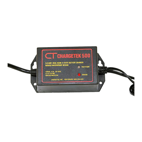
  9. Chargetek CT500 - 1 User manual

Chargetek CT500 - 1 User manual

Chargetek
409 Calle San Pablo, Unit 104, Camarillo, CA 93012 ~ Phone: (866) 482-7930 ~ Fax: (805) 482-7936

Please read the entire installation manual

are any questions or concerns, please email


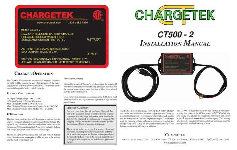
charger is totally waterproof and precisely
        
permanently mounted on almost any type
of vehicle including generators, ATVs, RVs,
lawn and garden tractors, snowmobiles,

product line is particularly suited for storage,
    
The charger can be left connected to the bat-

The CT500-1 is a three stage charger that
ensures that the battery is recharged with
precision and will be restored to its full ca-
pacity as fast as possible while prolonging


CT500-1


PARAMETER DESCRIPTION / CONDITIONS MIN NOM MAX UNITS
VFSTERM Fast charge voltage, 25C 14.4 14.5 14.6 VDC
VFLOAT Float voltage, IOUT < 1.0 A, 25 C 13.4 13.5 13.6 VDC
IFS Fast charge, VBATTERY = 12V 5.0 5.2 5.4 Amps
IFLTERM Float charge termination current 0.8 1.2 1.5 Amps
VAC RMS AC voltage range 180 240 264 VAC
ISBY Standby current, AC off 0.5 ma
Outline and mounting
LIMITED WARRANTY

at its discretion repair or replace for the original consumer,
free of charge, any part or parts found to be defective by






This is the exclusive remedy and consequential damages

The CT500-1 must be connected to the battery in order for the


The red wire connects to the positive and the black to the nega-


to check to be certain that the green light is on and the battery

Over temperature: The CT500-1 will reduce its charging current




ever illuminates, the unit should be removed and returned to
        

6.000
3.170
5.250
.21 x 2
.21 x 2
.44 x 2
1.750
6.000
2.580
.160
4.544
DC Output
Cord
AC Input
Cord
3.170
2.580
2.764
1.590
Dimensions in inches
CT500-1 operation

indicator lights inform the user of the progress of the charging

CT500-1 LED indicators
The dual color charging mode light indicates the state of charge





Installation
Location
Do not mount directly over or under a battery or onto a


hot surfaces such as exhaust pipes and moving parts such

        

Provide as much surrounding cooling clearance as possible

At a minimum, maintain a 3 inch clearance around the

Never mount in the vicinity of explosives, pressurized cans

Mounting
Wear safety goggles, gloves and a long sleeve shirt when



For extreme vibration conditions common in ATV and PWC
applications, added security such as crossed shock cords

Electrical
AC wire connections
The CT500-1 is equipped with a factory installed 6 foot AC

It is extremely important that
only grounded electrical outlets or extension cords with
a ground connection should be used when operating this
charger.
Never connect the AC plug into an electrical outlet if you are

Ensure that the AC cord cannot reach moving parts, lids,


The charger will operate properly with either 120 volts 50 Hz


DC wire connections
DC wire connections to the battery should be made before

The charger should only be used with lead-acid type batteries



When installing in the bilge of boats or any battery compart-
ment, ensure that hatches are open and bilge blowers are
operating for ten minutes to remove any fumes and hydrogen


Keep wire routing from the charger to the battery neat and
secure by anchoring with cable tie to a solid surface every

       


current source and additional protection is needed in the event
of physical damage to the DC cables or electrical damage to

(32 volts/5 amps rating) must be connected between the

an in-line fuse (32 volts/5 amps rating) must be connected
between the negative charger lead and the negative battery

The fuse’s mechanical attributes are installation and environ-


For a 24 volt battery system comrised of two 12V batteries
with a single inter-battery connection, the fusing is the same

the red lead is connected to the positive battery terminal and



When connecting two batteries in series, it is imperative that
the amount of charge and discharge be equal for both bat-

-
voltaged battery and will cause dangerous battery out gassing

Safety instructions
CAUTION: The following are important safety instructions.
Save these instructions.

       

           

Someone should be within the range of your voice and close
enough to come to your aid when you are working near a



Have plenty of fresh water and soap nearby in case the battery





         
Degradation of AC and DC cords, accidentally nicking or

Never operate a charger that has been damaged in any way




        
         

When using an extension cord, the CT500-1 requires a quality
grounded extension cord of at least 18 awg wire size for cords
up to 50 feet and a minimum of 16 awg for cords up to 150

       

The CT500-1 is waterproof and designed for harsh



is visibly damaged, disconnect the charger and consult the

Study the battery manufacturer’s precautions such as

   


Good battery maintenance procedures dictate that the battery





Remove personal metal items such as rings, bracelets,
necklaces, and watches when working with a lead-acid


Stage 1: Constant current or bulk charge mode
Assuming that the battery is starting in a discharged state, the
     
current is maintained at a constant value and the battery voltage


Stage 2: Absorption mode



This voltage is maintained until the charging current reduces


Stage 3: Float mode

mode, the voltage on the battery is maintained at approximately

will maintain the full charge condition of the battery without boil-

Three stage charging curve
Three stage charge cycle

charging procedure most lead-acid battery manufacturers rec-

24V battery system connectionTwo independent 12V battery connections
Battery
voltage
Stage 1: Bulk
(constant current)
Stage 2: Absorption
(constant voltage)
Voltage constant,
current decreasing
Battery
current
Absorption
Voltage constant,
full charge maintained
Stage 3: Float
(constant voltage)
Float
Bulk

Other Chargetek Batteries Charger manuals

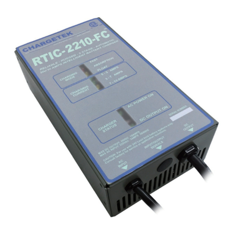
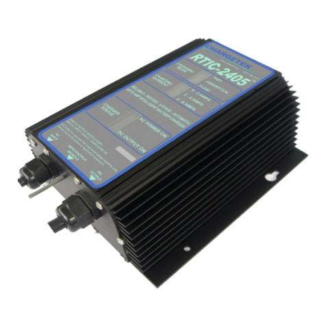
Chargetek RTIC-2210-FC User manual

Chargetek

Chargetek RTIC-2210-FC User manual

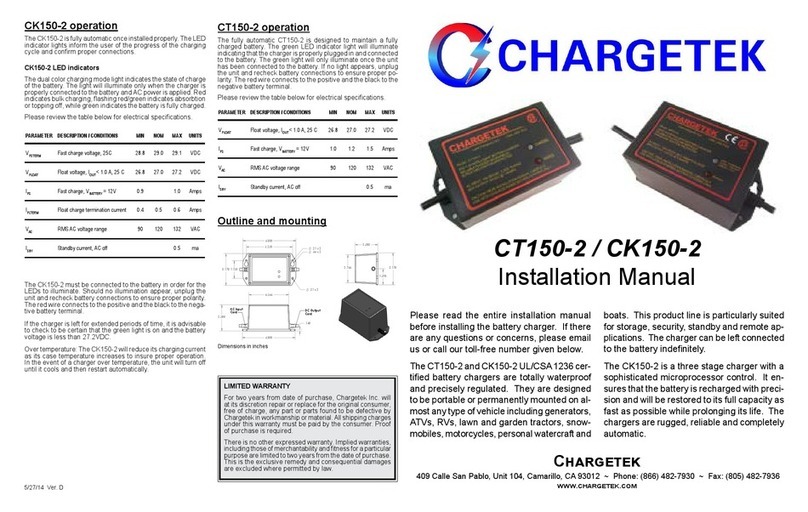
Chargetek CK150-2 User manual

Chargetek

Chargetek CK150-2 User manual

Chargetek TPRO-220 User manual

Chargetek

Chargetek TPRO-220 User manual

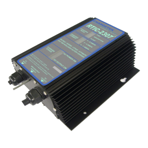
Chargetek RTIC-2307 User manual

Chargetek

Chargetek RTIC-2307 User manual

Chargetek CT500-3 User manual

Chargetek

Chargetek CT500-3 User manual

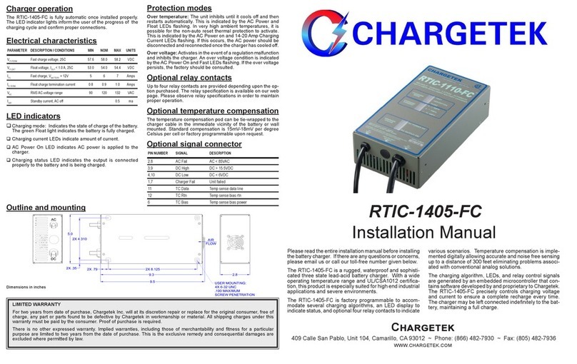
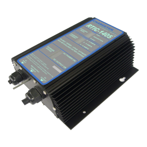
Chargetek RTIC-1405-FC User manual

Chargetek

Chargetek RTIC-1405-FC User manual

Chargetek RTIC-2307-FC User manual

Chargetek

Chargetek RTIC-2307-FC User manual

Chargetek RTIC-1307-WP User manual

Chargetek

Chargetek RTIC-1307-WP User manual

Chargetek RTIC-2405-FC User manual

Chargetek

Chargetek RTIC-2405-FC User manual

Chargetek RTIC-1210-FC User manual

Chargetek

Chargetek RTIC-1210-FC User manual

Chargetek CT500-5 User manual

Chargetek

Chargetek CT500-5 User manual

Chargetek RTIC 1120-WP User manual

Chargetek

Chargetek RTIC 1120-WP User manual

Chargetek RTIC-1120-WP User manual

Chargetek

Chargetek RTIC-1120-WP User manual

Chargetek RTIC-2210-WP User manual

Chargetek

Chargetek RTIC-2210-WP User manual

Chargetek CT500-6 User manual

Chargetek

Chargetek CT500-6 User manual

Chargetek RTIC-2120-FC User manual

Chargetek

Chargetek RTIC-2120-FC User manual

Chargetek RTIC-1120-FC User manual

Chargetek

Chargetek RTIC-1120-FC User manual

Chargetek RTIC-2120-WP User manual

Chargetek

Chargetek RTIC-2120-WP User manual

Chargetek RTIC-1307-FC User manual

Chargetek

Chargetek RTIC-1307-FC User manual

Chargetek RTIC 2405-WP User manual

Chargetek

Chargetek RTIC 2405-WP User manual

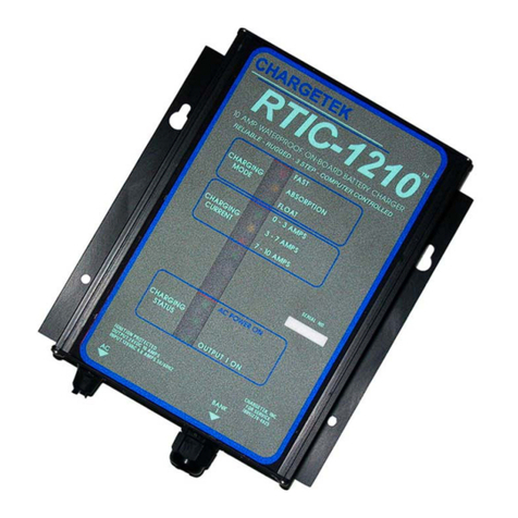
Chargetek RTIC-1210 User manual

Chargetek

Chargetek RTIC-1210 User manual

Chargetek RTIC-1405-WP User manual

Chargetek

Chargetek RTIC-1405-WP User manual

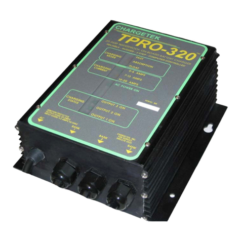
Chargetek TPRO-320 User manual

Chargetek

Chargetek TPRO-320 User manual

Chargetek CT500-2 User manual

Chargetek

Chargetek CT500-2 User manual

Popular Batteries Charger manuals by other brands

DSE DSE9473 installation instructions

DSE

DSE DSE9473 installation instructions

Rapoo XC100 quick start guide

Rapoo

Rapoo XC100 quick start guide

Delta-q RC Series Original instructions

Delta-q

Delta-q RC Series Original instructions

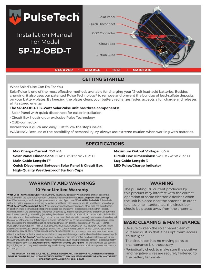
PulseTech SP-12-OBD-T installation manual

PulseTech

PulseTech SP-12-OBD-T installation manual

Würth Acctiva Easy Basic 1206 manual

Würth

Würth Acctiva Easy Basic 1206 manual

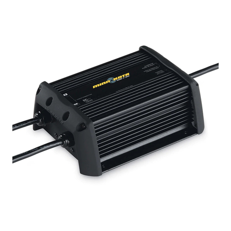
MINN KOTA MK-1-DC owner's manual

MINN KOTA

MINN KOTA MK-1-DC owner's manual

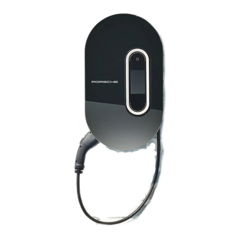
Porsche Wall Charger Connect instructions

Porsche

Porsche Wall Charger Connect instructions

Nitho XBX-CST6-K quick start guide

Nitho

Nitho XBX-CST6-K quick start guide

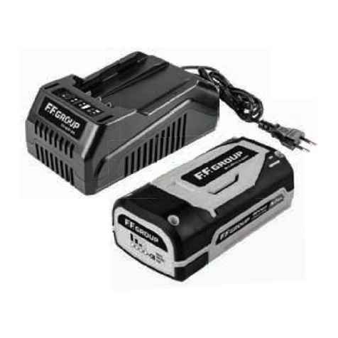
F.F. Group BLi 40V/5.0Ah Original instructions

F.F. Group

F.F. Group BLi 40V/5.0Ah Original instructions

Purkeys SELECT installation guide

Purkeys

Purkeys SELECT installation guide

Solar 1002 Operator's manual

Solar

Solar 1002 Operator's manual

Cristec CPS3OEM/24-40 user manual

Cristec

Cristec CPS3OEM/24-40 user manual

VONMÄHLEN AURA user manual

VONMÄHLEN

VONMÄHLEN AURA user manual

DSE DSE9701 installation instructions

DSE

DSE DSE9701 installation instructions

Cotek Easy Charger Wizard Product guide

Cotek

Cotek Easy Charger Wizard Product guide

CE-Link WPC10-1LCNA user manual

CE-Link

CE-Link WPC10-1LCNA user manual

Sony BC-L100 Operation and maintenance manual

Sony

Sony BC-L100 Operation and maintenance manual

Hoover ONEPWR BH15020 user manual

Hoover

Hoover ONEPWR BH15020 user manual

manuals.online logo
manuals.online logoBrands
  • About & Mission
  • Contact us
  • Privacy Policy
  • Terms and Conditions

Copyright 2025 Manuals.Online. All Rights Reserved.