manuals.online logo
Brands
  1. Home
  2. •
  3. Brands
  4. •
  5. Chatsworth Products
  6. •
  7. Industrial Equipment
  8. •
  9. Chatsworth Products Floor Supported Cube-It User manual

Chatsworth Products Floor Supported Cube-It User manual

FLOOR SUPPORTED CUBE-IT
IIS-739928, 11/7/18, Rev. 1, CPI/JAG
800-834-4969 (USA & Canada) • www.chatsworth.com • techsupport@chatsworth.com
For international phone numbers, see our website or contact CPI Tech Support.
This drawing contains proprietary and confidential information and is protected by U.S. and international law. Unauthorized reproduction, disclosure or use of the drawing or
the information therein is expressly forbidden except as agreed to in writing by Chatsworth Products, Inc.
Page 1 of 5
Installation Instructions
Safety Information
WARNING: Improper use of this product or failure to follow these
instructions may result in equipment damage, personal injury, or
death. Read and understand all instructions for proper installation
and use of this product.
WARNING: Before loading equipment in the cabinet, be sure all
parts and hardware are properly installed and tightened.
Intended Use
Install Floor Supported Cube-IT only in indoor, environmentally controlled areas;
do not use outdoors, in harsh environments or in air-handling spaces. Use this
rack for computer equipment, including servers and peripherals. Allow only
qualified service personnel to use this enclosure.
Tools Required
Included Hardware
13mm Socket
M8X40 LAG Screws
Qty 9
10mm Socket
M5.5X9 TAPTITE Screws
Qty 2
T25 TORX Driver
M6X10 Black TAPTITE Screws
Qty 2
T30 TORX Driver
M6 Star Washers
Qty 2
#2 Phillips Screw Driver
Grounding Wire
Qty 1
#1 Flat Screw Driver
Cable Grommets
Qty 5
3/8” Socket Extension
Door Keys
Qty 2
5/32 Drill Bit
3mm Hex Key
Qty 1
Center Chassis
Rear Panel
Door
Caster Kit
Plinth
LOAD CAPACITY: 1000lb (454kg)
FLOOR SUPPORTED CUBE-IT
Page 2 of 5
Installation Instructions
Removing from Pallet
1. Remove carton top and four corner protectors from cabinet.
2. The wheel kit and plinth ship packaged inside the cabinet. Remove both
boxes to install assemblies to cabinet.
3. Remove the six screws and washers that mount the cabinet to the pallet.
4. Move the cabinet off the pallet to the floor. CAUTION: USE TWO
PEOPLE TO REMOVE CABINET FROM PALLET TO PREVENT
TIPPING OVER.
5. To keep standard door swing, proceed to Plinth and Caster Kit
Installation instructions. To change door swing, follow Reverse Door
Swing instructions.
Reverse Door Swing (OPTIONAL)
1. Remove top access panel on rear panel by removing four hex nuts.
2. Remove the four plastic plugs from top of the center chassis.
3. Rotate entire cabinet so hinges are on opposite side.
4. Reinstall top access panel and plastic plugs.
5. Remove and reinstall door latch so that it is in correct orientation.
6. Remove and reinstall latch cam 180 degrees from default orientation.
7. Relocate CPI logo above swing handle.
Screw
Washer
Top Rear
Access Panel
Top Plugs
Door Latch
Logo
Swing
Handle
FLOOR SUPPORTED CUBE-IT
Page 3 of 5
Installation Instructions
Plinth Installation
1. Lay cabinet on its side and open door to access inside. Place cardboard
or other material on floor to protect cabinet paint finish.
2. Install Plinth to rear panel bottom using four M8 carriage bolts and
serrated flange hex nuts.
Caster Kit Installation
1. Install caster assembly to center chassis bottom using four M8 carriage
bolts and serrated flange hex nuts.
2. Install cover plate to caster assembly using four M5 screws.
WARNING: DO NOT STAND CABINET UNTIL READY TO
MOUNT TO WALL. CABINET MAY TIP OVER IF NOT
PROPERLY SECURED.
M8 Carriage Bolt
M8 Hex Nut
M8 Carriage Bolt
M8 Hex Nut
M5 Screw
FLOOR SUPPORTED CUBE-IT
Page 4 of 5
Installation Instructions
Mounting Cabinet to Wall
NOTE: These instructions are for mounting the cabinet to a wood studded wall
covered with 3/4" plywood. For masonry surface, the installer must provide
appropriate hardware.
1. Ensure the wall or mounting surface is structurally sound and able to
support the cabinet and expected payload. The mounting surface must be
flat and extend beyond the top, bottom, left, and right edges of the rear
panel.
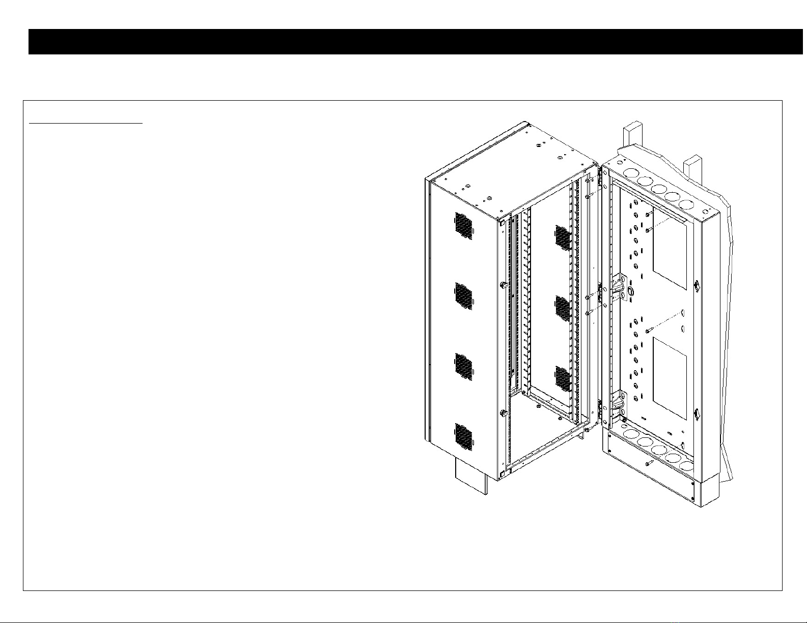
2. Determine wall location for mounting cabinet which allows the door and
center chassis to be opened 90 degrees from the rear panel.
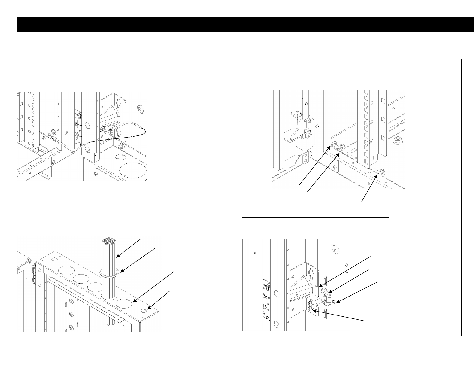
3. Mark center of selected wall studs to help position rear panel keyholes
before installing lag screws.
4. Position cabinet against the wall with mounting keyholes closest to three
main chassis hinges centered on a wall stud. Keyholes closest to center
should be located on a 16” spacing wall stud. Keyholes on opposite side
from hinges are for 24" spacing wall studs.
5. With the cabinet in position against wall, open the front door (do not hinge
cabinet body open from rear panel) to install three M8X40 Lag screws (1
at top, 1 at middle, 1 at bottom) in mounting keyholes of 16” or 24” wall
stud. Drill pilot holes using 5/32” drill bit for easier installation.
6. Open the cabinet body 90 degrees and install five M8X40 Lag screws in
mounting keyholes near hinges (2 at top, 2 at middle, 1 at bottom).
7. Install final lag bolt in top keyhole of 16” or 24” wall stud.
FLOOR SUPPORTED CUBE-IT
Page 5 of 5
Installation Instructions
Grounding Wire
1. Use M5.5 self-tapping Torx screws, star washers, and grounding wire to
electrically bond center chassis to rear panel using any accessory holes.
Cable Access
1. Per cabling requirements removable cable knockouts are provided on top and
bottom of rear panel. Knockouts are removed using a large flat-head screw driver.
2. Use provided rubber grommets on large knockouts. Alternatively, large knockouts
will accommodate 2-1/2” metal conduit. Small knockouts accommodate ¾” metal
conduit.
Equipment Rail Adjustment
1. Loosen M8 bolts, star washers, and hex nuts to move equipment rails to
desired depth spacing.
2. Tighten M8 bolts, star washers, and hex nuts to secure equipment rails.
Ground Jumper Wire (P/N 40159-009 sold separately)
1. Remove paint mask from grounding emboss with two holes.
2. Install ground jumper wire using two black M6 Torx TAPTITE screws.
3. Place grounding label next to ground emboss.
Cable Fill
Rubber Grommet
3in Knockout
1in Knockout
Grounding Emboss
Black M6 Torx Screw
Ground Jumper Wire
Grounding Label
M8 Carriage Bolt
Star Washer
M8 Hex Nut

Popular Industrial Equipment manuals by other brands

Rohloff SPEEDHUB 500/14 Mounting

Rohloff

Rohloff SPEEDHUB 500/14 Mounting

Loveshaw Little David LD16AR Operator's manual

Loveshaw

Loveshaw Little David LD16AR Operator's manual

Lenze G Series Operating	 instruction

Lenze

Lenze G Series Operating instruction

MachineryHouse Metalmaster PB-820A Operation manual

MachineryHouse

MachineryHouse Metalmaster PB-820A Operation manual

e2v EV10AQ190TPY-DK user guide

e2v

e2v EV10AQ190TPY-DK user guide

Photoneo Bin Picking Studio quick start guide

Photoneo

Photoneo Bin Picking Studio quick start guide

Drester RDX 9012 manual

Drester

Drester RDX 9012 manual

ABB HT612190 Operation manual

ABB

ABB HT612190 Operation manual

DH PGI Series Short manual

DH

DH PGI Series Short manual

Arrow Master 1350 Operator's manual

Arrow Master

Arrow Master 1350 Operator's manual

Zimmer CSR Series Installation and operating instructions

Zimmer

Zimmer CSR Series Installation and operating instructions

ABB HT587040 Operation manual

ABB

ABB HT587040 Operation manual

Western Global ECW105 manual

Western Global

Western Global ECW105 manual

Horizon Fitness MC-8 manual

Horizon Fitness

Horizon Fitness MC-8 manual

STM ROCKETBOX Training manual

STM

STM ROCKETBOX Training manual

Total Source 164TA9661 operating manual

Total Source

Total Source 164TA9661 operating manual

Siemens 3WN6 quick start guide

Siemens

Siemens 3WN6 quick start guide

SEW-Eurodrive MOVIGEAR MGF-DBC Series operating instructions

SEW-Eurodrive

SEW-Eurodrive MOVIGEAR MGF-DBC Series operating instructions

manuals.online logo
manuals.online logoBrands
  • About & Mission
  • Contact us
  • Privacy Policy
  • Terms and Conditions

Copyright 2025 Manuals.Online. All Rights Reserved.