Chauvet TFX-D12 User manual

Chauvet, 3000 N 29th Ct, Hollywood, FL 33020 U.S.A
(800) 762-1084 – (954) 929-1115
FAX (954) 929-5560
www.chauvetlighting.com
2004-11-11/11:32
TFX-D12
Stage Dimmer™ 12
USER MANUAL
UPMENU DOWN ESC
DMX
1 2 CH.DIGIT ALMODU LEDIMMER
STAGE DIMMER 12
TM

TFX-D12 User Manual 2 2004-11-11/11:32
TABLE OF CONTENT
TABLE OF CONTENT........................................................................................................................................................... 2
BEFORE YOU BEGIN........................................................................................................................................................... 3
WHAT IS INCLUDED................................................................................................................................................................................3
UNPACKING INSTRUCTIONS....................................................................................................................................................................3
WARNING.............................................................................................................................................................................................3
FEATURES............................................................................................................................................................................................3
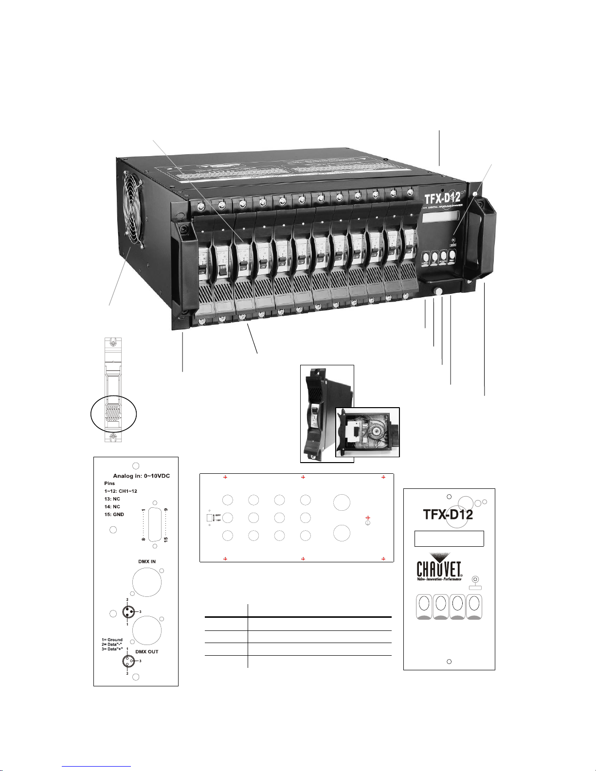
PRODUCT OVERVIEW ............................................................................................................................................................................4
INSTALLATION..................................................................................................................................................................... 5
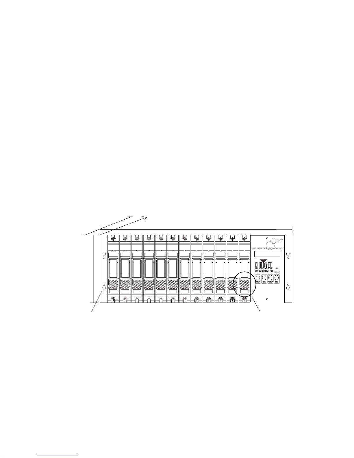
MOUNTING ...........................................................................................................................................................................................5
POWER CONNECTIONS..........................................................................................................................................................................6
Input Power................................................................................................................................................................... 6
Single-phase.......................................................................................................................................................................................................6
Three-phase.......................................................................................................................................................................................................6
Output Power................................................................................................................................................................ 7
Control Wiring............................................................................................................................................................... 7
DMX512..............................................................................................................................................................................................................7
Analog 0-10VDC.................................................................................................................................................................................................7
OPERATING INSTRUCTIONS.............................................................................................................................................. 8
START MENU........................................................................................................................................................................................8
MENU NAVIGATION................................................................................................................................................................................8
Setup Menu................................................................................................................................................................... 9
DMX Fail [Dmx fail]....................................................................................................................................................... 9
Hold, Analog.......................................................................................................................................................................................................9
Prog.01-12..........................................................................................................................................................................................................9
Phase Correction [Pha corr]........................................................................................................................................ 10
DMX Address [Dmx addr]........................................................................................................................................... 10
Block.................................................................................................................................................................................................................10
Single................................................................................................................................................................................................................10
Preheat [Preheat]........................................................................................................................................................ 11
All [All]...............................................................................................................................................................................................................11
Single Channel [Chan [1]]................................................................................................................................................................................11
Dimmer Curve [Curve]................................................................................................................................................ 11
Preset [Preset]............................................................................................................................................................ 12
All [All]...............................................................................................................................................................................................................12
Single Channel [Chan [1]]................................................................................................................................................................................12
APPENDIX........................................................................................................................................................................... 13
DMXPRIMER .....................................................................................................................................................................................13
Fixture Linking..................................................................................................................................................................................................13
MAINTENANCE ....................................................................................................................................................................................14
RETURNS PROCEDURE........................................................................................................................................................................14
CLAIMS ..............................................................................................................................................................................................14
TECHNICAL SPECIFICATIONS ................................................................................................................................................................15

TFX-D12 User Manual 3 2004-11-11/11:32
BEFORE YOU BEGIN
What is included
¾1 x Stage Dimmer™ 12 (TFX-D12)
¾Manual
¾Warranty Card
Unpacking Instructions
Immediately upon receiving a fixture, carefully unpack the carton, check the contents to ensure that
all parts are present, and have been received in good condition. Notify the shipper immediately and
retain packing material for inspection if any parts appear damaged from shipping or the carton itself
shows signs of mishandling. Save the carton and all packing materials. In the event that a fixture
must be returned to the factory, it is important that the fixture be returned in the original factory box
and packing.
Warning
•Please keep this User Guide for future consultation. If you sell the unit to another user, be sure that they also receive this instruction
booklet.
•Always make sure that you are connecting to the proper voltage and that the line voltage you are connecting to is not higher than that
stated on decal or rear panel of the fixture.
•This product is intended for indoor use only!
•To prevent risk of fire or shock, do not expose fixture to rain or moisture. Make sure there are no flammable materials close to the unit
while operating.
•The unit must be installed in a location with adequate ventilation, at least 50cm from adjacent surfaces. Be sure that no ventilation
slots are blocked.
Because Dimmer packs operate at potentially lethal high voltages, installation wiring should be done
by qualified persons only!
Do not connect chassis Ground to Neutral, or operate without chassis ground, otherwise the user
could be exposed to potentially lethal voltages.
Features
•12-channel DMX-512
dimmer/switch
•DMX-512 and Analog 0~10v DC
control
•Each channel individually DMX
addressable
•12 built-in beat-activated programs
(stand-alone)
•10 Amp magnetic circuit breaker in
each channel
•Individual dimmer modules
•LCD control panel is modular and
can also be replaced
•Set preheat voltage to individual
channel or all
•Dimmer curve selection; square,
switch or linear
•AC phase correction
•Power failure memory
•Digital display and menu navigation
buttons
•DMX signal loss failover function
•Thermal switch and short circuit
protection
•Fan cooled
Please read these instructions carefully, which includes important
information about the installation, usage and maintenance?

Introduction
TFX-D12 User Manual 4 2004-11-11/11:32
Product Overview
Modular dimmer module
LCD Display
MENU Button
UP Button
DOWN Button
ESC Button
Standard 19” EIA rack mountable
Carrying handles
Forced air cooling
DMX Signal
Indicator
10A Circuit breaker
Module air intake
I/O Panel
Knockout rear cover panel
BUTTON FUNCTION
MENU Access the set-up and menu functions
UP Scroll menu functions or increase values
DOWN Scroll menu functions or decrease values
ESC Go back one menu or leave menu system
Control Module
UPMENU DOWN ESC
DMX
2CH.DIGIT ALMODULEDIMMER
STAGE DIMMER 12
TM

TFX-D12 User Manual 5 2004-11-11/11:32
INSTALLATION
Mounting The TFX-D12 dimmer packs are designed to be mounted in a standard 19” EIA rack using the two
mounting holes on each flange/(ears). The two mounting flanges are designed for securing the
dimmer pack to the front rack mounting rails. It is highly recommended that you add support to the
rear of the dimmer pack, especially in touring or road case environments.
The TFX-D12 depends on forced air cooling and the following guidelines should be applied during
installation:
1. The rack enclosure must maintain a 4 inch minimum clearance on the entire left side
of the dimmer rack. The rack enclosure must not be sealed, and must maintain an air
exhaust clearance area of at least 20 square inches per installed pack to allow air flow
back to the ambient room.
2. The intake manifold on the front of the dimmer pack can never be blocked.
3. Ambient room temperature must never exceed 104°F/50°C
Failure to adhere to proper and safe installation guidelines may result in a VOID of warranty!
Rack ears
A
ir intake
Do Not Obstruct!
7”
19 ½“
17 ¾”

Operating Instructions
TFX-D12 User Manual 6 2004-11-11/11:32
Power Connections
Warning! Make certain that power is removed from
the circuits before you begin installation of the
dimmer. Consult your local electrical codes to
determine the proper wire type and wiring methods
for your regional installation.
Input Power
SINGLE-PHASE
THREE-PHASE
L
L1 L2 L3
N
NNN
E
EE
1
p
hase, 3 wire 120/240 VAC, 120 Am
p
s, 50~60Hz
POWER INPUT: - - - - - - AC 120V/230V~50/60Hz
OUTPUT: - - - - - - - - - - - 10A per channel, Total 120A
3
p
hase, 4 wire 120/240 VAC, 40 Am
p
s, 50~60Hz
L1
L2 L3
N
NNN
E
EE
L1
L2 L3
POWER INPUT: - - - - - - AC 120V/230V~50/60Hz
OUTPUT: 10A per channel, Total 40A per phase

TFX-D12 User Manual 7 2004-11-11/11:32
Output Power
Control Wiring
DMX512
Input: 3-pin XLR (male)
Output: 3-pin XLR (female)
Pin Signal
1 DGND
2 DATA ( - )
3 DATA ( + )
ANALOG 0-10VDC
Input: 15-pin M D-Sub
Pin Signal
1 Channel 1
2 Channel 2
3 Channel 3
4 Channel 4
5 Channel 5
6 Channel 6
7 Channel 7
8 Channel 8
9 Channel 9
10 Channel 10
11 Channel 11
12 Channel 12
13 NC
14 NC
15 Ground
LOADING
CH12
CH11
CH10
CH9
CH8 CH7 CH6 CH5 CH4 CH3 CH2 CH1 L3 L2 L1 NNNEE
EEEEEE

TFX-D12 User Manual 8 2004-11-11/11:32
OPERATING INSTRUCTIONS
Start Menu Upon powering the dimmer, the LCD panel will display the software version presently installed and
shortly after, will enter standby mode.
Menu Navigation
First line displays dimming
levels of each channel.
Second line displays the
channel.
A~C = 10~12
12345678 9ABC
12345678 9ABC
Dmx fail
Pha corr
Dmx addr
Preheat
Curve
Preset
Hold
Analog
Prog.01-12
Yes
No
Block
Single Channel
All
Single Channel
Linear
Switch
Square
All
Single Channel

Operating Instructions
TFX-D12 User Manual 9 2004-11-11/11:32
Dmx fail
Dmx fail
Prog08 Hold
–
The dimmer
will hold the last dmx
signal received.
Analog – The
dimmer will revert to
the Analog input
signal.
ProgXX - Will start
internal programs 1-
12.
Setup Menu Action
1) Press the MENU button to enter the setup
menu.
2) There are 6 menu items to choose from;
Dmx fail, Phase Correction, Dmx addr,
Preheat, Curve and Preset.
3) Press the UP and DOWN buttons to scroll
menu items.
4) Press ESC to exit the setup menu.
DMX Fail [Dmx fail]
The DMX Fail feature allows the user to select how the dimmer will behave if you were to loose the
DMX controller’s signal to the dimmer.
Action
1) Press the MENU button to enter the setup
menu.
2) Press the UP and DOWN buttons to scroll
menu items until you reach [Dmx fail].
3) Press MENU to enter the sub-menu.
4) If it were running the built-in scene 08 it
would display as per the illustration on the
right.
5) Press the UP/DOWN buttons to select one
of the following; [Hold], [Analog],
[Prog.01-12].
HOLD, ANALOG
1) Whether you choose Hold or Analog press
the ESC button to confirm and exit.
PROG.01-12
1) Press the ESC button to confirm.
2) Select a chasing speed from 0.1 to 20
seconds using the UP/DOWN button.
(Hold the UP/DOWN buttons for two seconds to change
speed quickly.)
3) Press the ESC button to confirm setting.
Dmx fail
(Hold) or (Analog)
Speed
00.3s

Operating Instructions
TFX-D12 User Manual 10 2004-11-11/11:32
Phase Correction [Pha corr]
Action
1) Press the MENU button to enter the setup
menu.
2) Press the UP/DOWN buttons until you
reach [Pha corr].
3) Press MENU to enter the sub-menu.
4) Press UP/DOWN buttons to choose
between Yes and No.
5) Press ESC button to activate.
DMX Address [Dmx addr]
Action
1) Press the MENU button to enter the setup
menu.
2) Press UP/DOWN buttons to choose
between [Block] and [Single]
configuration.
3) Press MENU button to enter the sub-menu.
BLOCK
1) Press the ESC button to confirm.
2) Press UP/DOWN buttons to select the start
address between 001 and 512.
SINGLE
1) In [Chan[1]]/Single Channel mode press
MENU to change between the channel and
its’ start address as noted by the cursor.
2) In [Chan], press UP/DOWN buttons to
select channels 1~12. In [001], press
UP/DOWN buttons to select dmx start
address [001-512].
3) Press the ESC button to exit and confirm.
Pha corr
(Yes) or (No)
Dmx addr
(Block) or (Single) Block
–
Block
addressing refers to
12 consecutive
channels using only
one starting address.
Single – Allows the
user to select a
starting address for
each channel.
Dmx addr
Block Start
[001]
Chan [1]
[001] Chan [1]
[001]

Operating Instructions
TFX-D12 User Manual 11 2004-11-11/11:32
Preheat [Preheat]
Action
1) Press the MENU button to enter the setup
menu.
2) Press the UP and DOWN buttons to scroll
menu items until you reach [Preheat].
3) Press MENU button to enter the sub-menu.
4) Press the UP/DOWN buttons to choose
between [All] and [Chan]/Single Channel
mode.
5) Press MENU to select mode.
ALL [All]
1) Press UP/DOWN to select the preheat
value between [000%] – [050%] for all
channels.
SINGLE CHANNEL [Chan [1]]
1) In [Chan [1]]/Single Channel mode press
MENU to change between the channel and
its’ start address as noted by the cursor.
2) In [Chan], press UP/DOWN buttons to
select channels 1~12. In [001], press
UP/DOWN buttons to select percentage
[000%-050%].
3) Press the ESC button to exit and confirm.
Dimmer Curve [Curve]
Action
1) Press the MENU button to enter the setup
menu.
2) Press the UP and DOWN buttons to scroll
menu items until you reach [Curve].
3) Press the MENU button to enter the sub-
menu.
4) Press UP/DOWN buttons to select from
Linear, Switch & Square dimmer curve.
5) Press ESC button to exit and confirm.
Preheat
All Chan [1]
[000%]
All
[005%]
Chan [1]
[050%]
Curve
(Linear)/(Switch)/(Square)

Operating Instructions
TFX-D12 User Manual 12 2004-11-11/11:32
Preset [Preset]
Action
1) Press the MENU button to enter the setup
menu.
2) Press the UP and DOWN buttons to scroll
menu items until you reach [Preset].
3) Press the MENU button to enter the sub-
menu.
4) Press UP/DOWN buttons to select between
All/Single Channel mode.
ALL [All]
1) Press UP/DOWN to select the master
dimmer level value between [000%] –
[100%] for all channels.
SINGLE CHANNEL [Chan [1]]
1) In [Chan [1]]/Single Channel mode press
MENU to change between the channel and
its’ start address as noted by a cursor.
2) In [Chan], press UP/DOWN buttons to
select channels 1~12. In [001], press
UP/DOWN buttons to select percentage
[000%-1*0%].
3) Press the ESC button to exit and confirm.
Preset
All
[000%]
Chan [1]
[030%]

TFX-D12 User Manual 13 2004-11-11/11:32
APPENDIX
DMX Primer
There are 512 channels in a DMX-512 connection. Channels may be assigned in any manner. A
fixture capable of receiving DMX 512 will require one or a number of sequential channels. The user
must assign a starting address on the fixture that indicates the first channel reserved in the controller.
There are many different types of DMX controllable fixtures and they all may vary in the total number
of channels required. Choosing a start address should be planned in advance. Channels should
never overlap. If they do, this will result in erratic operation of the fixtures whose starting address is
set incorrectly. You can however, control multiple fixtures of the same type using the same starting
address as long as the intended result is that of unison movement or operation. In other words, the
fixtures will be slaved together and all respond exactly the same.
DMX fixtures are designed to receive data through a serial Daisy Chain. A Daisy Chain connection is
where the DATA OUT of one fixture connects to the DATA IN of the next fixture. The order in which
the fixtures are connected is not important and has no effect on how a controller communicates to
each fixture. Use an order that provides for the easiest and most direct cabling. Connect fixtures
using shielded two conductor twisted pair cable with three pin XLR male to female connectors. The
shield connection is pin 1, while pin 2 is Data Negative (S-) and pin 3 is Data positive (S+). CHAUVET
carries 3-pin XLR DMX compliant cables, DMX-10 (33’), DMX-4.5 (15’) and DMX-1.5 (5’)
FIXTURE LINKING
Note! If you use a controller with a 5 pin DMX output connector, you will need to use a 5
pin to 3 pin adapter. CHAUVET Model No: DMX5M.
The chart below details a proper cable conversion:
3PIN TO 5PIN CONVERSION CHART
CONDUCTOR 3 Pin Female (output) 5 Pin Male (Input)
GROUND/SHIELD Pin 1 Pin 1
DATA (-)SIGNAL Pin 2 Pin 2
DATA (+)SIGNAL Pin 3 Pin 3
DO NOT USE Do not use
COMMON
DMX
+
DMX
-
INPUT OUTPUT
1
3
2
1
3
2
1
3
2
Resistance 120
ohm 1/4w between
pin 2 (DMX -) and
pin 3 (DMX +) of
the last fixture.
Termination reduces signal errors and to
avoid signal transmission problems and
interference, it is always advisable to connect
a DMX signal terminator.
DMX connector configuration

Appendix
TFX-D12 User Manual 14 2004-11-11/11:32
Maintenance
To maintain optimum performance and minimize wear fixtures should be cleaned frequently. Usage
and environment are contributing factors in determining frequency. As a general rule, fixtures should
be cleaned at least twice a month. Dust build can cause overheating. Be sure to power off fixture
before conducting maintenance.
Unplug fixture from power. Use a vacuum or air compressor and a soft brush to remove dust
collected on external vents and internal components.
Returns Procedure
Returned merchandise must be sent prepaid and in the original packing, call tags will not be issued.
Package must be clearly labeled with a Return Merchandise Authorization Number (RA #). Products
returned without an RA # will be refused. Call CHAUVET and request RA # prior to shipping the
fixture. Be prepared to provide the model number, serial number and a brief description of the cause
for the return. Be sure to properly pack fixture, any shipping damage resulting from inadequate
packaging is the customer’s responsibility. CHAUVET reserves the right to use its own discretion to
repair or replace product(s). As a suggestion, proper UPS packing or double-boxing is always a safe
method to use.
Claims Damage incurred in shipping is the responsibility of the shipper; therefore the damage must be
reported to the carrier upon receipt of merchandise. It is the customer's responsibility to notify and
submit claims with the shipper in the event that a fixture is damaged due to shipping. Any other claim
for items such as missing component/part, damage not related to shipping, and concealed damage,
must be made within seven (7) days of receiving merchandise.

Appendix
TFX-D12 User Manual 15 2004-11-11/11:32
Technical Specifications
WEIGHT & DIMENSIONS
Length......................................................................................................................... 451 mm (17.75 in)
Width ............................................................................................................................ 495 mm (19.5 in)
Height.................................................................................................................................178 mm (7 in)
Weight ............................................................................................................................27 Kg (59.5 lbs)
INPUT POWER
Switch-selectable power setting (on-board PCB)..........................................115V 60 Hz or 230V 50 Hz
Single-phase input....................................................... 3 wire + GD, 120/230 VAC, 120 Amps, 50-60Hz
Three-phase input ...................................................... 4 wire + GD, 120/230 VAC, 120 Amps, 50-60Hz
OUTPUT CAPACITY
120VAC, 12-channels .....................................................................1200 Watts per channel @ 120VAC
230VAC, 12-channels .....................................................................2300 Watts per channel @ 230VAC
OUTPUT PANEL
.......................................................................................................................Hard-wired terminal blocks
OVERLOAD PROTECTION
...................................................................................10 Amp Fast Acting Circuit Breakers per Channel
CONTROL & PROGRAMMING
Data input................................................................................................locking 3-pin XLR male socket
Data output...........................................................................................locking 3-pin XLR female socket
Data pin configuration ..............................................................................pin 1 shield, pin 2 (-), pin 3 (+)
Protocols........................................................................................................................DMX-512 USITT
DMX Channels .....................................................................................................................................12
Analog .............................................................................................................. 12 channels of 0-10VDC
ORDERING INFORMATION
Stage Dimmer™ 12...................................................................................................................TFX-D12
This manual suits for next models
2
Table of contents
Other Chauvet Dimmer manuals
Popular Dimmer manuals by other brands

AMX
AMX Single Channel Lutron FDB Ballast Dimmer... Installation sheet

Lutron Electronics
Lutron Electronics Caseta Pico PD-6WCL quick start guide

Leviton
Leviton Vizia RF RZM10-1L installation instructions

Lutron Electronics
Lutron Electronics Energi TriPak Series Quick start quide

Leviton
Leviton Decora Multi-Remote MSE0R-1 installation instructions

BEGA
BEGA 71148 Instructions for use