Chell microDAQ Operating instructions

Please read this manualcarefullybefore usingthe instrument.
Useof thisequipment in amannernotspecifiedin this
manual mayimpair the user’sprotection.
Chell Document No. :900167 Issue 1.3
ECO: 1270 Date: 28th November 2014
Chell’spolicy ofcontinuously updating andimproving products meansthatthismanualmay contain
minordifferences in specification &functionality fromtheactualinstrumentsupplied.

Contents
1. Introduction. ....................................................................................1
2. UserCommandProtocol................................................................2
2.1Command Packet......................................................................................................................................2
2.2Acknowledgement.....................................................................................................................................2
2.3UserCommands........................................................................................................................................2
3. StatusData Format. ........................................................................6
4. microDAQ CommunicationChannels............................................7
4.1RS232.......................................................................................................................................................7
4.1.1 Overview. ............................................................................................................................................7
4.1.2Connection..........................................................................................................................................7
4.1.3RS232 Protocol...................................................................................................................................7
4.1.4Control ViaRS232...............................................................................................................................7
4.1.5 DataRate ............................................................................................................................................7
4.2TCP.............................................................................................................................................................8
4.2.1Overview. ............................................................................................................................................8
4.2.2Connection..........................................................................................................................................8
4.2.3TCP Protocol.......................................................................................................................................8
4.2.4TCP DataRate.....................................................................................................................................8
4.2.5Control ViaTCP...................................................................................................................................9
4.3CAN ............................................................................................................................................................9
4.3.1Overview. ............................................................................................................................................9
4.3.2CAN Baudrate.....................................................................................................................................9
4.3.3CAN Protocol....................................................................................................................................10
4.3.4CAN DataRate..................................................................................................................................12
4.3.5Control ViaCAN................................................................................................................................12
4.4Internal RAM............................................................................................................................................12
4.4.1Overview. ..........................................................................................................................................12
4.4.2Internal RAM Protocol.......................................................................................................................13
4.4.3Internal RAM DataRate.....................................................................................................................13
4.4.4Internal RAM Dump...........................................................................................................................13
5. ValveControl usercommands .....................................................14

Page 1
1. Introduction.
Frompowerup,the microDAQreads itsnon volatilesetupinformation andcalibration,andafter
applyingthesesettings isthen ‘upandrunning’,readingthe scanneranddeliveringcalibrated
data.Althoughformanyapplicationsthisisenough, moredemandingapplicationsmayneedto
controlthe data delivery, requestdata rezerooperationsandmore.
The microDAQsupportsauserinterface protocoltaken directly fromthe old CANdaqsystem,
allowingremoteaccess tothe essentialcommands requiredwhen integratingthe unitintoan
instrumentation system.Commands maybesentoveranyof the unit’scommunication channels,
whetherthe currentactive data channelornot.Asimpleblockparitycheckadds securitytothe
commandprotocol, andacorrectly receivedcommandmaybe acknowledgedif required.
The followingsetsoutthe essentials of the commandprotocol,the data packetformat forall
channels in addition tothe message identifierarrangementforthe CAN channel.
Thisdocumentcontainsall relevantcommands inheritedfromthe CANdaqsystemandin addition
covers the updatestosomecommands forstreamingtoInternalRAMandnewcommands for
dumpingthe InternalRAMtoothercomms(InternalRAMsupportisonly validformicroDAQ
firmware V1.0.8onwards).
Thisdocumentalsodetails the usercommands forvalve controls that arefoundin the flightDAQ
andthe microQDVP module which use the same commandprotocol.
Thisdocumentversion supports V1.0.14 ofthe microDAQfirmwareandV1.0.18 of the flightDAQ
fimrware.Ifusingearlierfirmwarethen someusercommandsand/or parameters may beinvalid.In
thiscasepleaserefertoanearlierversion of thisdocument – availableon request,fromChell
Instruments.

Page 2
2. UserCommand Protocol.
2.1CommandPacket.
The commandprotocolisbasedaroundasimpledelimitedcontrolpacket,allowingeasy
identification of commandstartandend.The packetincludesablockparitybyteincreasingthe
robustness of transmission; the packetformat isshown in Figure 2.1.
>(ASCII 62) Command Parameter Parity <(ASCII 60)
Figure 2.1CommandFrame Format.
The commandbytevaluesaredefinedin the followingsection,and mayormaynotrequirea
parameterbyte, forexampledata rate. The paritybyteisaneven blockparityof all bytes(other
thanitself),includingthe delimiters.Calculation forparitybit nisthereforethe sumof each bit n
usingmodulo2arithmetic.
Foracommandnotrequiringaparameter,anarbitrary dummybyteshould beused.Thiscanbe
anyvalue asthe numberisnotprocessedotherthanin determiningthe parityof the command
packet.
Example.
The commandsetincludesatestcommand(for use fromRS232 only),value 37 (ASCII "%").The
responsetothe commandistoecho backthe string"Test commandrxdok n",wherenisthe
value of the parameterbyte. Thismaybe checkedfromaterminalprogram by typing:
>%dC< ie byte values62, 37, 100, 67, 60
The parametervalue issetat 100, sothe paritybyte is62 ⊕37 ⊕100 ⊕60 =67.
The microDAQshould reply with "Test commandrxdok 100"
2.2Acknowledgement.
Acommandpacketispositively acknowledgedif itiscorrectly formattedandthe paritybyteis
correct.Apositive acknowledgementisdenotedby the transmission of ASCII 42 ('*'),anegative
acknowledgeindicatinganinvalidcommandby ASCII 33 ('!').Recognisedcommandvaluesare
then actedupon, though unrecognisedvaluesare discarded.
2.3User Commands.
The available usercommandsetissummarisedin Figure 2.2.
Command
(*DTConly) Byte,
Char/
ASCII
Parameter Description
Standby S/83 None Set all datastreaming off.
Reset R/82 None Requestasoftdevicereset - microDAQ isreinitialised.
Rezero Z/90 None Requestarezero, thenumber ofsamplesasset in
microDAQSetup.
Derange* D/68 None Calibration isrebuilt withtheappropriate deranging factor
applied, theDTCscanner deranging gain isswitchedinto
circuit.

Page 3
Rebuild
Calibration C/67 None Thecalibration isrebuilt forthecurrenttemperature,using the
active microDAQ settings
Filter F/70 0 - Off
1 - 2
2 - 4
3 - 8
4 - 16
5 - 32
6 - 64
7 - 128
8 - 256
9 - 512
10 - 1024
11 - 2048
12 - 4096
13 - 8192
14 - 16384
15 - 32768
16 - 65536
17 - Reset on Ouptut
Adjusttheoutputfilter setting thatisappliedafter thecalibration
within themicroDAQ.Ifswitching thedatadelivery rate
betweenslow andfastvalues,itmaybedesirable toadjustthe
amountofoutputfiltering accordingly.Alsotheaverage
between delivery option maybechosen through thiscommand.
Thevalueoftheparameter reflectsthenumber ofsamplesin
theoutputmoving average.Inthecaseof'Reset on Output',
themeasuredpressure valueisaveraged over thetimebetween
datadelivery cycles.
Rezero and
Rebuild G/71 None Requestsarezerofollowedbyacalibration table rebuild, with
thecalculatedzerooffsetsbeing appliedtothecalibration
data.. Note theserezerooffsetsare separate fromanynormal
rezero thatmaybeperformed afterwards.
Rate V/86 byte =0xab
a=0RS232
a=1TCP
a=2CAN
a=3InternalRAM
ForRS232 :
b =0:Off
b =1 :20 Hz
b =2 :10 Hz
b = 3 :5Hz
b = 4 :2Hz
b = 5 :1Hz
ForTCP:
b =0:Off
b = 1:1000Hz
b =2 :625Hz
b =3 :500 Hz
b =4 :400 Hz
b =5 :312 Hz
b =6 :225 Hz
b =7 :200 Hz
b =8 :150 Hz
b =9 :100 Hz
b =10 : 50 Hz
b =11 : 25 Hz
b =12 : 20 Hz
b =13 : 10 Hz
b =14 : 5 Hz
b =15 : 1 Hz
ForCAN &Internal
RAM:
b = 0:Off
b =1:1000 Hz
Adjustthedatadelivery rate foreachcommunication channel.
Theupper nibble oftheparameter byte selectswhich
communication channel, while thelower selectsitsdatarate.
CAN&InternalRAM‘comms’have thesameavailable data
rates.

Page 4
b =2:750 Hz
b =3:625 Hz
b =4:500 Hz
b =5:312 Hz
b =6:100 Hz
b =7:50 Hz
b =8:25 Hz
b =9:10 Hz
b =10 :5Hz
b =11 :2Hz
b =12 :1Hz
Protocol P/80 byte =0xab
a=0RS232
a=1TCP
a=2CAN
b =0 - 16 bit LE
b =1 - 16 bit BE
b =2 -
Engineering Units
Permitsthechanging ofthedataprotocol.Theabbreviations
LE andBEin thetable refer tolittle andbig endian respectively,
denoting whether theless significantbyte issentfirstorlast.
Pressure dataare available in engineering unitsover both
RS232 andTCPconnections,though only binary dataare
available with CAN and InternalRAM.
Binary dataprovidespressure scaledasunsignedintegersto
theoperating full scale,egfor16 bitresolution, 0 to65535
represents -FSDto +FSD.
StreamON 1/49 0 - RS232
1 - TCP
2 - CAN
3 - InternalRAM
4 - InternalRAM(stop
on full)
Enable thedatadelivery forthechosenchannel.Thedelivery
rate isasselectedin microDAQsetup, unless itismodifiedvia
the Rate command.
InternalRAMdatastreaming will either log continuously,
wrapping when theend of available RAMisreached, orwill stop
when theRAMisfull, depending on parameter.
StreamOFF 0/48 0 - RS232
1 - TCP
2 - CAN
3 - InternalRAM
Disable thedatadelivery forthechosen channel.
Get Status ?/63 0 :Short
1:With temp.
2:Full
3:Pressure reading
4:Temp. readings
5:Excitation reading
6:Hall sensor read
7:Firmware ID
8:Unitserial number
9:Scanner serial
number
Returnastatuspacket from themicroDAQ. Three main versions
are available,'short','withtemp.' and'full'.Short returnsstatus
byte information showing currentoperating state only,whereas
'full' returns microDAQ setup optionsandtemperature datain
addition. 'With temp.' returnsthestatusandtemperature
information intendedforcontinuoustemperature monitoring
applications.Thedataformatisdocumentedin aseparate
section.
Additionalreadingspoll raw valuesfortemperature and
pressure asreadfromthescanner,aswell asother fieldsas
indicated in thetable
Channels H/72 byte =0xab
a=0RS232
a=1TCP
a=2CAN
a=3InternalRAM
b =0 - 16
b =1 - 32
b =2 - 48
b =3 - 64
Set thenumber ofactive channelsreturnedtotheuser fora
datachannel.Setting avaluegreater than thecurrentsystem
maximumchannels(set via setup/dtcscanner readorbythe
MaximumChannelscommand)resultsin themaximum
channelsvaluebeing used.
Maximum
Channels M/77 0 - 16
1 - 32
2 - 64
Set thesystemmaximumchannels,iethenumber ofchannels
readfromthescanner.Allowsthedynamicalteration ofthe
effective per channel sampling rate

Page 5
Poll O/79 0 - RS232
1 - TCP
2 – CAN
Requestasingle datapacket (in thecurrentactive format)for
thechannel selected. Datastreaming shouldbeset off before
using thiscommand. Note thatthere isno positive
acknowledgeforthiscommand. Thiscommandisnotvalid for
logging to InternalRAM.
Span A/65 None Requesta‘span’ operation. Theunitshould have been recently
rezeroed, thentheappropriate span pressure (asselectedfrom
thesetup software)appliedtothescanner.Requesting aspan
operation will thencalculate thespan correction coefficientfor
eachchannel.All rezerovaluesandspan coefficientsare then
writtentotheunit’sEEPROM(NOTtothescanner),andthe
calibration tablesrebuilt using thesenew values.
Reset Linear
Calibration E/69 None Resetsthelinearcalibration (iezeroandspan values) held
within theunitto0and1.0respectively forall channels.A
calibration table rebuild isthen performed.
Hardware
Trigger T/84 byte =0xab
a=0Disable
a=1Enable
b =0RS232
b =1TCP
b =2CAN
b =3InternalRAM
b =4InternalRAM
(stop on full)
Enablesordisablesthehardware trigger on theselected
channel.Note thatthere isno positive acknowledgeforthis
command.
Assuming avalid hardware trigger isdetectedfortheduration,
InternalRAMdatastreaming will either log continuously,
wrapping (andtherefore overwriting)whentheend ofavailable
RAMisreached, orwill stop whentheRAMisfull (and
automatically disable thehardware trigger),depending on the
parameter.
Start Internal
RAMDump I/73 0 - RS232
1 - TCP
2 - CAN
StartstheinternalRAMdump, sending datausing thecomms
channel chosen bytheparameter. Thefirstpacket issent
immediately and consistsofa 9 byte header (only 6bytesfor
CAN - see later)
InternalRAM
Dump
Handshake
J/74 None Handshakecommand to indicate previouspacket wasreceived.
Mustbe sentafter header packet & all subsequentdata
packets.
Figure 2.2, TheAvailable User CommandSetfor themicroDAQ.

Page 6
3. Status DataFormat.
Statusdata isnotcurrently supportedoverthe CANchannel,howeverforRS232 andTCP
connections,statusdata mayberequestedfrom the microDAQ asthree forms – ‘short’,‘full’and
‘withtemp’.The shortformreturns4bytes,the 16 bitstatusword delimitedby the ASCII
characters ">" and"<",the less significantbyteisreturnedbeforethe moresignificant.The bit
assignmentis shown in figure 3.1.
15 I-daq
conn. Hardware
Trigger
Active
Derange
acvtive DTC
conn. CAN
Active TCP
Active RS232
active Cal.
table Span Rezero
Figure 3.1, Statuswordbitassignment.
Requestingthe status'withtemp.' returnsthe shortstatus4 bytes,followedby the temperature
data.Foranon DTC scanner,asinglevalue (ASCII unsigned14 bit) representingthe read
temperaturevoltageisappendedtothe statusbytes.ForaDTC application,all active channels
are returnedin ascendingorder ascomma delimitedASCII engineeringunits(ie degreesC).
The 'full'statusdata containsthe above, followedby fields forthe setupoptionsof the microDAQ.
Each field iscomma delimited,anditsfunction isindicatedin plain text between square
parentheses.On/off isindicatedby 1/0.Anexample'full'statusstringisshownin figure3.2for a
microDAQwithanon DTC scanner. Notethat the figure forfull scale includesthe derange constant
(ie scannerfull scale xderange constant) if the derange option hasbeen selectedin setup.
Figure 3.2, Full statusinformation.
*>Mó<8198,[Full scale]15.00000000,[Active channels]32,[DTC active]
0,[CANchannels]32,[TCPchannels]32,[RS232 channels]32,[CANrate]
OFF,[TCPrate]OFF,[RS232 rate]OFF,[CANprotocol]16 LE,[TCPprotocol]
16 LE,[RS232 protocol]16 LE,[Press.inputimpulse]1,[Temp.inputimpulse]
0,[Press.inputpower] 3,[Temp.inputpower] 0,[Press.outputpower] 0,[Reset
on delivery] 0,[Temp.compensation]0,[Period] 10m,[IP]0.0.0.0,[Mask]
0.0.0.0,[Gateway]0.0.0.0,[CANtiming](BRP) 5(TSEG1)2(TSEG2)0(SJW)
1,[CAN message]00n,[Rezeroorder] 4,

Page 7
4. microDAQ Communication Channels.
4.1RS232
4.1.1Overview.
Streamingdata overRS232 allowsaccess tocalibratedpressuredata withno frontendsoftware
support,asengineeringunitdata maybevieweddirectly in aterminalprogram such as
Hyperterminal®.RS232 maybeadequateforsomelowspeedapplications,thoughitsuse
requiresthe downclockingof the microDAQ’s systemclockandscanneraddressingto5kHzfrom
the defaultmaximum20kHz.
4.1.2Connection
Connection to the microDAQ viaRS232 requiresonly that the communicatingdevice hasitsserial
portparameters setcorrectly tomatch the microDAQ.The parameters otherthanbaudrateare
fixedas8bits,no parity,1stopbit,no flowcontrol.Baudrateisassetin microDAQSetup,avalue
between 9600 and115200 baud (typically 57600).
4.1.3RS232 Protocol.
Withthe RS232 channelselectedon,calibratedpressuredata arestreamedcontinuously overthe
serialinterface. Pressurereadings areformedintopacketsof one readingperchannelat the
desireddata delivery rate, andsenttothe client.RS232 supports 3 differentdata formatsas
shownin Figure4.1.The binary data formatsscalethe data to0to 65535 representing -/+ full
scalerespectively. Binary protocols requireless communicationsbandwidthaswell asless
processoroverheadwithin the microDAQ;itisrecommendedthat engineeringunitconversionsbe
appliedat the client.
Protocol Example data format Note
16 bit LE
0x00 0xFF 0x00 CH1LSBCH1MSBCH2LSB
CH2MSBCH3LSB…..CHNLSBCHNMSB 3 byte (00, FF, 00)headeridentifies
startofpacket.All activechannels
(CH1to CHN) then sent LSBfirst,
no delimiters.
16 bit BE 0x00 0xFF 0x00 CH1MSBCH1LSBCH2MSB
CH2LSBCH3MSB….. CHNMSBCHNLSB 16 bit data,3byte header,no
delimiters, MSBfirst.
Eng. Units *,#.#####,#.#####,#.#####,#.###
##,#.#####,#.#####……..#.##### ASCII readablestring,*(ASCII 42)
asheader,activechannelsin
ascending order,5decimalplaces,
commadelimited.
Figure 4.1, Data PacketProtocol, RS232 Channel.
4.1.4Control Via RS232
Incomingbyteson the microDAQ’s serialinputarebuffered,andif 5successive bytesmakeupa
commandpacket,the contentsaredecodedandanappropriateacknowledgementissued(‘*’ for
positive, ‘!’fornegative)on the serialport.Ifthe contentsof the packetareavalidcommand,itwill
then be carriedout.
Notethat if data packetsarebeingsenton the RS232 channel, the acknowledgementis likely tobe
lostwithin the data,unless the data delivery ismutedwiththe ‘Stream Off’commandbeforethe
commandissent.Itisrecommendedthat a‘Stream Off’(or‘Standby’command)isissuedbefore
anyothercommand.
4.1.5DataRate
Data ratesselectableforthe RS232 delivery channelare(Hz)1,2,5,10,20.Highervalues of data
rate are betterservedwith aTCP orCAN connection.

Page 8
4.2TCP
4.2.1Overview.
The microDAQ’s TCPchannelaffords itthe abilitytostream realtimepressuredata at highspeed
overstandard 100MbitEthernetconnections.
4.2.2Connection.
When usingthe TCP/IPchannel, the microDAQ isprogrammedtolisten on itslocalportnumber
101.Itwill respondtoaconnection request,connectandimmediately startstreamingdata if ithas
been setup touse the TCPchannel. Note that the microDAQ only supports one TCPconnection.
Setuprequires the microDAQ tobegiven anIPaddress,andthe network’ssubnetmask.It is
possibleeithertorun the microDAQ overalocalEthernetconnection,ordirectly fromaPC’s
network card, aslongasacrossovercable isused. Adualnetwork card (or2cards)maybe used,
howevercareshould betaken aboutnetwork routing,assimilarsubnetsfortwonetwork
connectionson asingleWindows ® machine cancause the microDAQ not tobeseen on the
secondcard.The microDAQ will respondtoa‘ping’instruction forthe purposesof setupand
troubleshooting.
4.2.3TCPProtocol
The microDAQ’s TCPdata protocolissharedwiththe RS232 serialdata stream protocol,andis
repeatedhere forcompleteness.
Inthe caseof the TCPchannel,the engineeringunitprotocolshould beavoidedif possible, due to
the needtodeclock the microDAQ’sinternalclockandscanneraddressingto10kHzfromthe
defaultmaximum20kHz(due tointernalissuesregardingstringhandling).The 16 bitlittleended
protocolismostefficientfromthe microDAQ’sviewpoint,the data beingcalibratedandspannedto
0to65535 (zeroat 32767).Scalingtofloatingpointfull scaleisbetterachievedwithin aPCclient
application wherethereismoreprocessingpoweravailable. Figure4.2showsthe availabledata
packetformatsoverTCP.
Protocol Exampledata format Note
16 bit LE
0x00 0xFF 0x00 CH1LSBCH1MSBCH2LSB
CH2MSBCH3LSB…..CHNLSBCHNMSB 3 byte (00, FF, 00)headeridentifies
startofpacket.All activechannels
(CH1to CHN) then sent LSBfirst,
no delimiters.
16 bit BE 0x00 0xFF 0x00 CH1MSBCH1LSBCH2MSB
CH2LSBCH3MSB….. CHNMSBCHNLSB 16 bit data,3byte header,no
delimiters, MSBfirst.
Eng. Units *,#.#####,#.#####,#.#####,#.###
##,#.#####,#.#####……..#.##### ASCII readablestring,*(ASCII 42)
asheader,activechannelsin
ascending order,5decimalplaces,
commadelimited.
Figure 4.2, Data PacketProtocol, TCPChannel.
4.2.4TCPDataRate.
The data delivery rateisselectedfromthe setupprogram,andthe followingvaluesareavailable
(Hz) – 1,5,10, 20, 25,50,100,150, 200, 225,312,400,500,625,1000.Althoughthe system
endeavours todeliverthe ratewithmaximumaccuracy,ultimateresponsibilityfordata timinglies
with the user’shostsystem.
Notethat since the scanners areaddressedat afixedchannelrate (20kHzif configuredforGen1
scanners,50kHzif configuredforGen2scanners),requestinga data delivery of morethan20k/No.
Channels (Gen1) or50k/No. Channels (Gen2) - i.e.312Hzfora64 channel Gen 1 scanner) -

Page 9
wastesresourcesandin somecasescanactually causethe microDAQto hang andrequirea
powercycle.
The data rateoverTCPisvulnerabletolowleveloperatingsystemconsiderations,in particularany
‘delayedacknowledgement’ algorithm.Windows®attemptstosuppress too many
acknowledgmentsforsmall data packetsswampinganetwork by insertinga200ms(default) delay
in the generation of asecondacknowledgementtoacommunicatingdevice. Since the microDAQ’s
communication consistsof manysmall packetsat ahighrepeat rate, thisalgorithmhasa
catastrophic effecton the microDAQ’s deliveredbandwidth (effectively limitingit totensof Hz).
The bottleneckcanberemovedby altering/addingavalue of the registry key:
HKLM\System\CurrentControlSet\Services\Tcpip\Parameters\Interfaces\{adapter GUID}
(HKLM =HKEY_LOCAL_MACHINE; {adapter GUID= the network adapterbeingusedby the
WindowsPC), though thisshould be done only in consultation with the network administrator.
In Windows2000, the DWORD value TcpDelAckTicks should be setto0in the registry key.
InWindowsXP(musthave SP1orlaterinstalled),the DWORD value TcpAckFrequencyshould be
setto1in the registry key.
Alsonotethat the TCPchannelof the microDAQ issubjecttobufferingbothwithin the unititself
(the size of the bufferdependingon numberof channels anddata rate),andwithin Windows®
itself. At lowdata rates,itispossibletoreceive singlecompletedata packets,howeverasthe data
rateincreasesWindows®ismorelikely todeliverchunks of data 2kto4kbytesin length, with
arbitrary boundarieswithrespectto microDAQ’s data packets.User softwareshould takethisinto
accounttoavoidlosingdata.
Pleasenotethat if streamingat highdata ratesitisessentialthat agoodnetwork infrastructure is
used.Itisrecommendedthat anystreamingisperformedovera‘private’network (i.e.
disconnectedfromanycorporatenetwork structure)toreduce the numberof packetsflyingaround
the network.Itisalsohighly recommendedthat ahigh speedmanagednetwork switch with alarge
storeandforward bufferisusedbetween the microDAQandclient PC,particularly if several
microDAQsare beingusedtogethertoacquire data.
4.2.5Control Via TCP.
Usercommands arehandledin asimilarwayasthe RS232 commands above, howeveritshould
benotedthat the acknowledgementbytesaredoubledforthe purposesof the internalworkings of
the TCPsoftware, soapositive acknowledgementisreturnedas‘**’ andanegative
acknowledgementas‘!!’.
The argumentregardingloss of acknowledgementsin the data stream holds goodforthe TCP
channel,anditisrecommendedthat a‘Stream Off’or‘Standby’issentbeforeanyother
command.
4.3CAN
4.3.1Overview.
The CANchannelissomewhat differenttothe above channels,in that itisnotasimpleserial
communicationschannel, the data beingsentin discrete chunks on specifiedmessage identifiers.
4.3.2CANBaudrate.
The microDAQ offers asingle‘standard’CANbusconnection runningat aselectablebaudrate, the
userhavingaccess tothe valuesusedfor the microDAQ’s microcontrollerCANtimingregisters to
enablecustomisingof samplepointandjumpwidth. Defaultvaluesforanumberof common
baudrates(1M,500k,250k,125k,100k,50k(Hz)) areavailablefromthe microDAQSetupprogram.
The valuesarecalculatedbasedon the microcontrollerCANperipheralclockof 60MHz. Users
should bearthisin mindwhen calculating suitablevaluesforBRP,TSEG1,TSEG2andSJWfor
theirown physicalnetwork implementation.

Page 10
4.3.3CANProtocol.
Twoseparateprotocols areavailablefromthe setup – eithermultipleorsinglemessage. Forthe
former, the microDAQ isallocatedafixedmessageforeach groupof 4pressurechannels,ie fora
64 channelscanner,16 discreteCANmessageidentifiers arerequired.Alternatively foramore
economicaluseof identifiers within asystem,asinglemessageidmaybeused,withall channels
sentoverthismessagesequentially.Channelnumbers arepositively identifiedwithachannel
identifierbyte within the message.
Forthe multiplemessageoption,data aresenton 8bytemessages,4channels permessage – the
pressurechannels associatedwithaparticularmessagenumberbeingfixed. The 2most
significantdigitsof the messageidentifierareuserselectableviathe setupprogram – sofor
examplethe identifierforchannels 1-4foruser selected0x22n would be0x220,andthe identifiers
forchannels 5-8,9-12 etc. followon incrementally fromthisfirstidentifierasshownin Figure4.3.It
isthe user’sresponsibilitytoavoidoverlapof messageidentifiers in amultiple microDAQ
installation.
Data aretwobytesunsigned,scaledto+/- full scale, ie 0x0000 mightrepresent –5psi,0xffff +5psi.
The data areuserselectableas16 bit bigorlittle ended. An example of the packingisillustratedin
Figure4.3.Useof the 16 bitlittle endedoption isrecommendedas it requires leastprocessor
overheadwithin the microDAQ unit.
The singlemessageidentifieroption isincludedtoreduce the numberof messageid’srequired
within asystem.Data arepackedin 7bytemessagesas3channels permessagewithone
channelidentifierbyte. Thisidentifierbyteisincrementedforeach messagein the sequence,
startingat 0x00 forchannels 1,23,then 0x01 forchannels 4,5,6etc. Odd leftoverchannels (eg16
channels/3=5full messagesplusamessagewithasinglechannelandtwo‘leftovers’) aresetto
0x0000 andshould bediscarded.Figure4.4showsthe structureof amessageforthe single
messageidentifierprotocol.Aselectableintermessagedelayof between 1msand200msis
availableto match messagegeneration timingtothe user’ssystem.Notethat itisthe user’s
responsibilitytoselectappropriate delays with respecttochannelrate andCAN busbaudrate.

Page 11
MessageID
Data Byte
0x220
0x221 0x222 0x223 0x224 0x225 0x226 0x227
7 CH4
MSB CH8
MSB CH12
MSB CH16
MSB CH20
MSB CH24
MSB CH28
MSB CH32
MSB
6 CH4
LSB CH8
LSB CH12
LSB CH16
LSB CH20
LSB CH24
LSB CH28
LSB CH32
LSB
5 CH3
MSB CH7
MSB CH11
MSB CH15
MSB CH19
MSB CH23
MSB CH27
MSB CH31
MSB
4 CH3
LSB CH7
LSB CH11
LSB CH15
LSB CH19
LSB CH23
LSB CH27
LSB CH31
LSB
3 CH2
MSB CH6
MSB CH10
MSB CH14
MSB CH18
MSB CH22
MSB CH26
MSB CH30
MSB
2 CH2
LSB CH6
LSB CH10
LSB CH14
LSB CH18
LSB CH22
LSB CH26
LSB CH30
LSB
1 CH1
MSB CH5
MSB CH9
MSB CH13
MSB CH17
MSB CH21
MSB CH25
MSB CH29
MSB
0 Ch1
LSB Ch5
LSB Ch9
LSB Ch13
LSB Ch17
LSB Ch21
LSB Ch25
LSB Ch29
LSB
Figure 4.3, Example of CANmultiple message packing fora32 channel
scanner, using the16 bitlittle endeddata protocol – baseidentifier 0x220.
Data Byte Content
6 CH3 - MSB
5 CH3 - LSB
4 CH2 - MSB
3 CH2 - LSB
2 CH1 - MSB
1 CH1 - LSB
0 0x00
Figure 4.4, Example of theCANsingle message protocol using 16 bitlittle
endeddata– first message (iechannels1,2,3)

Page 12
4.3.4CANDataRate.
The data delivery rateisselectedfromthesetupprogram,andthe followingvaluesareavailable
(Hz) – 1,2,5,10,25,50,100,312,500,625,750,1000.Althoughthe systemendeavours todeliver
the ratewithmaximumaccuracy,ultimateresponsibilityfordata timinglieswiththe user’shost
system.
Careshould betaken in selection of delivery rate, asitispossibletoselectunfeasibly fastdata
delivery foraparticularbusbaudrate, resultingin data loss.Similarly since the scanners are
addressedat afixedchannelrateof 20kHz (Gen1)or50kHz(Gen2),requestingadata delivery of
morethan20k/No. Channels or50k/No. channels - ie 312Hzfora64 channel Gen1 scanner -
wastesresourcesandin some casescan cause the microDAQtohang, requiringapowercycle.
4.3.5Control Via CAN.
The usercommandsetissupportedover the microDAQ’sCANchannel. The specification and
function of the commands aredetailedin section 2 above, howeverthe CANimplementation isas
follows.
The incomingmessagenumberisselectedby the userfromthe frontendsoftware, thoughis
constrainedtoberelative tothe outgoingdata basemessageidentifier.The offsetfromthe base
identifiermaybeselectedasbeing+0x10, +0x20, +0x30, +0x40 or+0x50. Forexample the base
data messageidentifierof 0x220 mightbesetuptoreceive commands overCANon message
0x230 (0x220 +0x10).
Inaddition tothe incomingmessageoffset,the usermayselectwhetherthe incomingcommandis
acknowledgedornot.The usercommandisadelimited5bytemessagethat includesablock
paritycheck,asshownin Figure4.5.Ifthe commandisreceivedwithoutdetectederror,andthe
acknowledgeoption hasbeen selected, MicroDAQ will respondtoausercommandwithapositive
acknowledgebyte(‘*’ orASCII 42).Alternatively,ifthe commandisreceivedincorrectly itwill
respondwiththe negative acknowlegebyte(‘!’orASCII 33).The acknowledgementissentasa
singlebytemessagewithidentifierone greaterthanthe receivingmessage. Forthe above
example, the acknowledge will be senton message 0x231.
DataByte Content
4 < (ASCII 60)
3 Parity
2 Parameter
1 Command
0 > (ASCII 62)
Figure 4.5, Data Structure of theCANIncoming Control Message.
4.4 Internal RAM.
4.4.1 Overview.
Data acquisition tointernalRAM allowsforfastacquisition withoutthe potentially limitingfactorof
externalcommshardware(e.g.network hubs,PCCANinterfaces,etc.).Data canbeacquiredat
whateverspeedisnecessary andthen dumpedtothe hostPCasapost-acqusition task.

Page 13
4.4.2 Internal RAM Protocol.
The data protocols availableforinternalRAMstorageare16bitlittleendianorbigendianonly.
Engineeringunitconversion should beperformedon the hostPConce acquireddata hasbeen
dumpedtothe PC.
4.4.3 Internal RAM Data Rate.
The rateat which the data isacquiredintoInternalRAMisdeterminedby the rateusercommand,
andthe followingvaluesare available (Hz) – 1, 2, 5, 10, 25, 50, 100, 312, 500, 625, 750, 1000.
As withothercommunications channels,careshould betaken nottorequestadata delivery of
more than 20k/No. channels (ie 312Hz fora64 channelscanner).
4.4.4 Internal RAMDump.
Data canbedumpedfrominternalRAMon anyof the otherthree availablecommunications
channels.The format of the data dumpisdesignedtobe(almost) the sameasif data wasbeing
streamedoutof that communicationschannel.So forRS232 &TCPthe format of data isthe same
asthe 16bitLEorBEprotocolformatsdetailedin sections4.1.3&4.2.3above (ie.Channeldata
precededby a3byteheader(0x00,0xFF,0x00).ForCANthe format of the data isdependanton
the selectedCANmessagetype(singlemessageormultiplemessageIDs)asdetailedin section
4.3.3above.
In addition tothe above, aninternalRAMdumpsends a 9(or6)byteheader, which is sentassoon
asthe ‘StartInternalRAMDump’usercommandhasbeen receivedby the microDAQ.Thisheader
hasthe followingformat (notethe firstthree bytesare not sentif the commschannelusedforthe
dumpisCAN).
Data Byte Content
8
Total sizeofdata
dump (inbytes)
7
6
5
4 Blocks perop
3 Numberofchannels
2* 0x00
1* 0xFF
0* 0x00
Figure 4.6, Data structure of InternalRAM dumpheader packet
(bytesmarked*are notsentwhen dumping viaCANcomms)
‘Blocks perop’details the numberof cyclesof ‘n’channels that aresentin one transmission
packet – thisisdependanton the numberof channels beingacquired (byte 3in headerabove) and
isirrelevantforCAN(always setto1).Aftereach packet issent, the microDAQwaitsfora
handshaketoconfirmthat the packet of data hasbeen receivedat the hostPCend.The dump
handshakeusercommandshould besentby the hostPC tofacilitatethis (Notetoavoiddeadlock,
the microDAQwill waitforamaximum10 seconds forthe handshakebeforeautosendingthe next
packet). Ahandshake isalsoexpectedafterthe headerpackethasbeen sentby the microDAQ.

Page 14
5. ValveControl usercommands
The flightDAQunitcontainsbothmicroDAQhardwareandadditionally containstwosolenoid
valvestocontrol the shuttleof the MeasurementSpecialtiesscanners that arepartof the flightDAQ
unit andalsocontainsanelectricaldrive signalforcontrollinganexternalpurgevalve. The
microQDVPmoduleisanaccessory tothe microDAQunit that alsocontainsthe valvinganddrive
signal.
The controlof thesevalvesisdone via the samecommandprotocolaswiththe othermicroDAQ
commands (see previoussectionsabove).Forthe microQDVPaseparatecommsconnection has
tobemadeto the module(via RS232,EthernetorCAN), whereasforthe flightDAQthe commands
arejustan extension of the standard commandsetandcanbetransmittedall throughthe same
commsconnection.Thesecommands changethe valvesaccordingly toperforma zero function or
apurge function andalsotosimply move the shuttle valve between CAL &RUN
Here followsthe description of those usercommands:
Command
Byte,
Char/
ASCII
Parameter Description
Zero W/87 0-255 – number of
secondsto waitin
CALbefore switching
backto RUN
Performs aZero function:
1. Shuttle scanner to CALmode
2. Waitforconfigured time(fromParameter byte)
3. Shuttle scanner to RUNmode
Purge U/85 0-255 – number of
secondsto wait
whilstPurging
Performs aPurgefunction:
1. Shuttle scanner to CALmode
2. Switch on externalpurgevalve
3. Waitforconfigured time(fromParameter byte)
4. Switch off externalpurgevalve
5. Shuttle scanner to RUNmode
Shuttle Y/89 0 – shuttle to CAL
1 – shuttle to RUN Movesthescanner shuttle valve between CALand RUNmodes.
Table of contents
Other Chell Scanner manuals
Popular Scanner manuals by other brands

Epson
Epson Perfection V700 Series Service manual
Avision
Avision AD340GFN user manual
Datalogic
Datalogic Magellan 3450VSi Product reference guide

Hand Held Products
Hand Held Products IMAGETEAM 5620 System manual
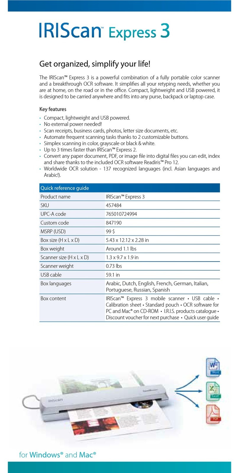
IRIScan
IRIScan Express 3 Quick reference guide

Visioneer
Visioneer PaperPort OneTouch installation guide

