Chell Q-Daq User manual

Chell Instruments Ltd
Folgate House
Folgate Road
North Walsham
Norfolk NR28 0AJ
ENGLAND
Tel: 01692 500555
Fax: 01692 500088
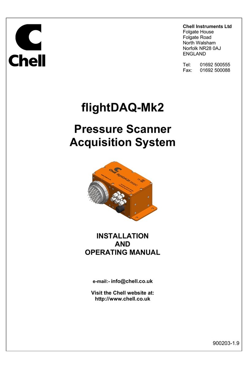
Q-Daq
Pressure Scanner
Acquisition System
INSTALLATION
AND
OPERATING MANUAL
Cover models : Q-Daq PoE and
Q-Daq DC
e-mail:- info@chell.co.uk
Visit the Chell website at:
http://www.chell.co.uk
900223-1.0

Page 1
Please read this manual carefully before using the instrument.
Use of this equipment in a manner not specified in this
manual may impair the user’s protection.
Chell Document No. : 900223 Issue 1.0
ECO : 03255 Date: 1/8/2019
Chell’s policy of continuously updating and improving products means that this manual may contain
minor differences in specification, components and software design from the actual instrument
supplied.

Page 2
CONTENTS
1 Description ............................................................................................................................ 3
1.1 General............................................................................................................................................................. 3
2 Specifications .................................................................................................................... 4
2.1 PoE Specification ............................................................................................................................................ 4
2.2 Power Supply (Q-Daq DC Only):.................................................................................................................... 4
2.3 CAN specifications (Q-Daq DC only):............................................................................................................ 4
2.4 Ethernet Specifications: .................................................................................................................................. 4
2.5 Environmental specification:........................................................................................................................... 4
2.6 Mechanical specifications. ............................................................................................................................... 4
2.7 Heater Specifications ....................................................................................................................................... 5
2.6 Dimensions ....................................................................................................................................................... 5
2.6.1 Q-Daq-PoE................................................................................................................................................. 5
3 Installation and Interconnections ..................................................................................... 6
3.1 Electrical connections ..................................................................................................................................... 6
3.1.1 Q-Daq PoE Electrical connections (M12 connector)............................................................................... 6
3.2 Q-Daq Pneumatic Connections....................................................................................................................... 6
4 Operation of the instrument .............................................................................................. 7
4.1 Connecting up the Q-Daq. .............................................................................................................................. 7
4.2 Configuring the Q-Daq ..................................................................................................................................... 7
4.3 Re-zeroing the Q-Daq. .................................................................................................................................... 7
4.4 Hardware Trigger (Q-Daq DC only) ............................................................................................................... 8
4.4.1 Hardware Trigger Input (Q-Daq DC only)................................................................................................... 8
4.4.2 Timing Information (Q-Daq DC only) .......................................................................................................... 8
4.4.3 Software Control....................................................................................................................................... 8
5 Q-Daq Configuration Webserver .......................................................................................... 9
5.1 Introduction. ..................................................................................................................................................... 9
5.2 Common Controls Sidebar ........................................................................................................................... 11
5.3 The 'Setup Parameters' Page....................................................................................................................... 12
5.3.1 Introduction ............................................................................................................................................. 12
5.3.2 Data Streaming....................................................................................................................................... 12
5.3.3 TCP Parameters ..................................................................................................................................... 13
5.3.4 UDP Parameters..................................................................................................................................... 13
5.3.5 CAN Parameters (Q-Daq DC only) ........................................................................................................... 14
5.4. ‘Live Data’ Page ........................................................................................................................................... 15
5.5 ‘Advanced’ Page............................................................................................................................................ 16
5.5.1 Advanced communication settings........................................................................................................ 16
5.5.2 Miscellaneous ......................................................................................................................................... 17
5.5.4 Zero Coefficients..................................................................................................................................... 18
5.6 Timestamp ................................................................................................................................................ 19
6. Service and Calibration ..................................................................................................... 20
6.1 Service ........................................................................................................................................................... 20
6.2 Calibration ...................................................................................................................................................... 20
6.3 Adjustment ..................................................................................................................................................... 20
6.4 Cleaning ......................................................................................................................................................... 20

Page 3
1 Description
1.1 General
The Q-Daq is a self-contained pressure scanner that acquires and transmits pressure data to a host
via Ethernet or a CAN bus. The Q-Daq is mechanically based on the Chell SQDC range giving the
user the ability to connect it to an existing SQDC loom or, with the appropriate mating half, connect
the Q-Daq to flexible or solid tubing.
The Q-Daq range consists of two of models which are covered by this manual. These are the Q-Daq
PoE with is powered by Power over Ethernet (PoE) and features an M12 connector. This variant of
the Q-Daq does not have the facility for CAN communications or hardware trigger. The DC powered
version (D-Daq DC) does have the CAN and hardware trigger facility and is powered by a DC voltage
of 8 to 25 VDC.
Both devices have the ability to output absolute pressures or differential pressures. When differential
pressures are required, one of the 16 transducers is selected as the reference and subtracted from
the other 15 measurements.
Both Q-Daq models have a built-in heater which can be controlled via the web interface. The heater
is capable of maintaining a temperature of around 30°C above ambient and it can be set to control
any given temperature from -55°C to 70°C.
The Q-Daq is configured by using its embedded web-server. The output can be configured in a
number of ways including averaging, transmission speed, absolute or differential and also the ability
to add a time stamp to the data (compliant with IEEE1588 PTP v2).
This manual revision covers firmware version 1.0.0 PoE.

Page 4
2 Specifications
2.1 PoE Specification
802.3af/bt Class 3 10W maximum
2.2 Power Supply (Q-Daq DC Only):
Line voltage:
8-25 VDC
Absolute Max. Line voltage
25 VDC
Consumption:
Max 1VA
2.3 CAN specifications (Q-Daq DC only):
CAN type
2.0B
CAN baudrate
Configurable from 1M, 500K, 125K and 100K.
Programmable variables:
Address 0x?nn
Most significant programmable device ID
Address 0xn?n
Next most significant programmable device ID
BRP
CAN bus timing
TSEG1
CAN bus timing
TSEG2
CAN bus timing
SJW
CAN bus timing
2.4 Ethernet Specifications:
TCP/IP
10Mb/s & 100Mb/s via Auto Negotiation
TCP & UDP protocols supported
2.5 Environmental specification:
Operating temperature range:
-40°C to +90°C
Storage temperature range:
-40°C to +90°C
Maximum Relative humidity:
95% at 50°C (non condensing)
Ambient altitude (provisional)
100 mbar abs or nominally 52000 ft
Vibration (provisional)
Engine standard vibration test to DO160E category S,
curve W with duration of 1 hr/axis. Fan blade out case
to DO160E category S, curve P.
Fan blade out to DO160F section 7 (40g 11m/s)
Engine load to +/- 40g per axis
Radiated emissions
MIL standard 461-E: RE102
Conducted emissions
MIL standard 461-E/MIL standard 461-C
2.6 Mechanical specifications.
Pneumatic interface:
16 way SQDC male – will interface with:
SQDC-R-16-01 to SQDC-R-16-07
Weight :
340g
Environmental sealing:
IP67

Page 5
2.7 Heater Specifications
Controlable between -55 and 70
°
C (via Webserver). 7.5 watts power.
2.6 Dimensions
2.6.1 Q-Daq-PoE

Page 6
3 Installation and Interconnections
3.1 Electrical connections
3.1.1 Q-Daq PoE Electrical connections (M12 connector)
3.2 Q-Daq Pneumatic Connections
For Details on the SQDC interface, please refer to the SQDC data (SL00914.pdf) sheet and manual
(90014723.pdf)
Hot plugging the power to the Q-Daq at the connector can cause permanent damage to
the unit. Always switch the power at the power supply source.
Pin
Function
1
MDX0+
2
MDX0-
3
MDX1+
4
MDX1-
5
MDX3+
6
MDX3-
7
MDX2+
8
MDX2-

Page 7
4 Operation of the instrument
4.1 Connecting up the Q-Daq.
The Q-Daq has one connector and cable which supplies the unit with power and also provides CAN
(Q-Daq DC only) and Ethernet comms. Ensure all the connections are made before powering up the
Q-Daq. The Q-Daq should not be hot plugged with the power connector. Doing so can cause
permanent damage to the unit. Always switch the power at the power supply source.
Upon power up, the blue LED will light constantly while the Q-Daq boots up. This will typically take
around 2 seconds. When the Q-Daq has finished booting, the blue LED will flash at a constant rate to
show that the system is running (unless auto hardware trigger enable has been set – see later).
To connect to the Q-Daq, establish an Ethernet connection to the Q-Daq using the appropriate cables
and check that the necessary link lights are lit. The host PC must have an i/p address in the same
range as the Q-Daq. For example, if the Q-Daq had an i/p address of 192.168.1.190 then (depending
on the subnet mask used) the first three octets of the subnet mask should be the same – i.e.
192.168.1.XXX. Once the connection has been established, the i/p address can be changed and the
Q-Daq connected to the user network.
NOTE: If the i/p address is changed, it is very important that a record is made of the new i/p address
as it cannot be ascertained without returning the unit to Chell Instruments.
4.2 Configuring the Q-Daq
The Q-Daq is designed to be configured by using the embedded web server. Here all the product
variables may be changed including i/p address, CAN i/d, averaging, transmission speed etc. Once
these setting are configured, they can be permanently saved by clicking on ‘BURN TO EEPROM’.
Once the unit is reset, the Q-Daq will run using these setting.
The Q-Daq can be configured to output data over CAN (Q-Daq DC only) or Ethernet (TCP/IP or UDP)
and, if configured to do so, it will output this data immediately upon power up. The Q-Daq can also
accept commands over the Ethernet or CAN networks to configure the majority of the internal setting
(with the exception of CAN i/d, i/p address and some lower level functions). Please refer to document
900222 – nanoDaq-LT user programming guide for available CAN and Ethernet commands and the
format of the data output stream.
4.3 Re-zeroing the Q-Daq.
It is possible to re-zero the output of the Q-Daq for either absolute or differential measurements.
The Q-Daq is re-zeroed by sending the appropriate command over the CAN or Ethernet link via the
Chell software or via the embedded webserver. The system will then average a number of zero
readings and perform a re-zero. Naturally, there should be no pressure applied to the ports of the
scanner when a re-zero is being performed.
When a re-zero is being performed, the red LED will light momentarily. The re-zero value is not stored
in volatile memory and will be lost upon reset. See section 5.5.4 for permanently saving the zero
values if necessary.

Page 8
4.4 Hardware Trigger (Q-Daq DC only)
The Q-Daq features a hardware trigger to enable the user to synchronise multiple Q-Daq’s and to
calculate the timing of the measurements made. The hardware trigger takes the form of a pulse train.
Each time the Q-Daq receives a positive edge, it will generate a set of measurements for all the
channels configured in the system.
4.4.1 Hardware Trigger Input (Q-Daq DC only)
The hardware trigger input is a 5V TTL square wave pulse train. Minimum frequency 2Hz and
maximum frequency 180KHz.
4.4.2 Timing Information (Q-Daq DC only)
The hardware trigger allows the user to calculate the time of each measurement. For example, if the
hardware trigger were running at 100Hz then the user would receive 100 measurements per channel
per second. The first pulse would generate the first set of measurements and 10ms later the second
pulse would generate the second set and so on. When the hardware trigger is activated, the Q-Daq
will wait for the first pulse. The time that this first pulse is generated can be measured by the user and
therefore the time of the first set of data and all subsequent sets can be determined
4.4.3 Software Control
The hardware trigger mode is activated by the T command over the CAN or Ethernet interfaces. The
T command can be used to enable the hardware trigger that will cause the Q-Daq to stop free-running
and wait for the first pulse. The disable command will return the Q-Daq to free-running. The command
structure is as follows:
Command
Interface
On / Off
T01
CAN
Off
T11
CAN
On
T02
Ethernet
Off
T12
Ethernet
On
The hardware trigger can also be set to auto enable on power up which means that the Q-Daq will
not go into free-running mode after initialisation and will instead wait for the first hardware trigger
pulse. In this instance the blue LED will not flash at a constant rate after initialisation and will actually
turn off. This feature can be enabled/disabled from the embedded webserver configuration.

Page 9
5 Q-Daq Configuration Webserver
5.1 Introduction.
The Q-Daq web Configuration provides the means of setting up and demonstrating the Q-Daq unit
from a standard PC with an Ethernet port and browser.
The webserver is divided by tabs into five areas of functionality, namely 'Setup’, 'Live Data',
‘Advanced’, ‘Timestamp’ and ‘Factory Tools’.
'Setup Parameters' provides the means to set Q-Daq’s main operating parameters such as data
streaming rates and Device addresses.
The unit's function may be checked and demonstrated using 'Live Data' to show the Q-Daq’s
calibrated output.
‘Advanced’ provides setup for the all other more advance parameters that may require setting on a
per application basis.
‘Timestamp’ provides some options for configuring the timestamping feature of the Q-Daq.
‘Factory Tools’ provides some functionality to change the MAC address of the Ethernet hardware.
This tab is password protected and therefore not readily available to everyone and further detail is
beyond the scope of this document.

Page 10
Figure 5.1, Main Setup page

Page 11
5.2 Common Controls Sidebar
Figure 5.1 above shows the first page viewed when navigating to the
webserver. It includes the common controls sidebar and the main group
of setup parameters. The sidebar provides information on the Q-Daq unit
including serial numbers and current firmware revision along with the
configured scanner full scales and total channels. The function of the
common controls is detailed in the subsequent table (Table 5.1)
Table 5.1, Common sidebar control functions.
Figure 5.2, Sidebar
Control
Function
'RESET' button
Resets the Q-Daq , similar to power cycling the device. Use to activate
new settings and/or rebuild calibration tables.
'Rezero' button
Starts a Q-Daq rezero operation.
‘Burn to eeprom”
button
Burns all changes made to the local settings into the eeprom so they
can be retrieved on restart.

Page 12
5.3 The 'Setup Parameters' Page
5.3.1 Introduction
The 'Setup Parameters' page shows all of the Q-Daq's main operating parameters. Setup Parameters
is divided into different categories by function, and each category is detailed separately in the
following.
5.3.2 Data Streaming
The ‘Data Streaming’ section allows the user to change settings that affect all three communication
protocols, and allows the user to choose the protocol that is to be used, along with the data transfer
rate.
Figure 5.3, Data Streaming group
Control
Function
‘Comms Protocol’ radio button
Chooses the communication protocol that is to be used. This button changes what
options are available below it.
‘Data Rate’ option list
Selects the rate at which the Q-Daq will automatically transmit data after reset. The
maximum data rate available will be changed by which Oversampling rate is
selected.
‘Protocol’ option list
Selects the format that the data will be transmitted as, options are 16 bit LE, 16 bit
BE for all protocols and eng. units as an extra option for TCP and UDP Comms.
‘Apply’ button
Applies the changes made to the local settings memory.
Pressure Input Average Samples
Displays the number of samples used for deriving the average pressure.
Table 5.2, Data Streaming settings.
Note that selecting Engineering Units for a protocol will cause the scanner addressing rate to be
reduced; it is better to scale calibrated 16 bit data to engineering units within the client software.
It should also be noted that changing the data rate also changes the Pressure input averaging
samples to the maximum value that will not have any detrimental effect on the dynamic response of
the Q-Daq.
The max measurement per channel per second value is gained from the oversampling rate, so when
the oversampling is in high speed mode, this value will be 180 Hz, in low resolution mode it will be
130 Hz, in standard resolution it will be 100 Hz, in high resolution mode it will be 50 Hz and in ultra
high resolution it will be 25 Hz. The default oversampling setting is standard resolution.
Averaging required = max measurement per channel / requested data rate

Page 13
The average required is then dropped to the next value down in the averaging index. An averaging of
1 is equal to off.
So, if the Oversampling is on High resolution and the data rate selected is 5Hz then the
Pressure and Temperature input average samples will be 4.
5.3.3 TCP Parameters
The TCP communication protocol parameters are shown in Figure 5.3. This only shows if the TCP
radio button is selected in the datastreaming section. The options in this section control the Q-Daq’s
IP address, subnet mask and Local port.
Figure 5.4, TCP Comms group
'IP Address'
IP address allocated to Q-Daq on the user's network.
'Subnet'
Subnet mask as set on the user's network.
‘Local port’
Local port of the device.
‘Apply TCP’
Applies the settings to the local memory
Table 5.3, TCP Comms group settings
5.3.4 UDP Parameters
The UDP section (figure 5.4) holds all the settings specific to UDP. In UDP mode each acquisition
cycle (of ‘x’ number of channels) is packed as a separate UDP packet with a four-byte representation
of the Q-Daq serial number at the start of the packet. These are attempted to be sent out at the
required rate but with no checking for reception or validity of data.
It is also possible to change the output data packet format to IENA specification format by using the
check box.
Note that the Q-Daq’s local IP address is the same setting as from the TCP Comms group.

Page 14
Figure 5.5, UDP Comms group
‘Local IP address and subnet’
This displays the IP address of the Q-Daq, this is the same as in the TCP comms
section.
‘Local port’
Local port of the device.
‘Remote UDP IP address’.
Address of remote connection to Q-Daq. If set then the Q-Daq can be set to auto
stream data to that remote host on boot up (after initialisation)
‘Remote UDP port.’
Port of remote connection to Q-Daq. If set then the Q-Daq can be set to auto stream
data to that remote host on boot up (after initialisation)
‘Use IENA Specification for data
stream’
Changes the format of data output packets to IENA specification.
‘Apply’
Applies the settings to the local settings memory
Table 5.4, UDP Comms group settings
5.3.5 CAN Parameters (Q-Daq DC only)
The CAN communication settings are shown in Figure 5.5. Options are available to set the base
message ID number may be selected, and the offset from this base number for the reception of user
commands over CAN, and whether an acknowledgement of these user commands is sent on the next
higher message number. Data may be transmitted on either multiple messages, or alternatively on a
single message ID, with a selectable delay between messages.
Figure 5.6, CAN Comms group
‘CAN First TX Message ID’
Q-Daq uses standard CAN message arbitration id’s, and the unit is assigned the most
significant 2 digits of the Hex base address. For the digits 0x1A for example, data for
the first 4 channels will be sent on 0x1A0, the next 4 on 0x1A1, etc.
Message scheme/delay
Select ‘Multiple Messages’ for the 4 channels per message, multiple message
scheme. Alternatively, data may be packed 3 channels per message + identifier byte,
with a selectable delay between messages.
‘CAN RX ID Offset’
Selects the hex offset from the base message ID where Q-Daq will receive incoming
user commands (see user command document). If ‘Ack. Enabled’ is selected, the unit
will acknowledge the reception of a correctly formatted command on the message ID
calculated as Base ID + RX Offset + 1
‘Apply’
Applies the settings to the local settings memory
Table 5.5, CAN Comms group settings.

Page 15
5.4. ‘Live Data’ Page
Figure 5.6 shows the 'Live Data' page of the webserver, for a 16-channel pressure scanner.
Figure 5.7, Live Data Page
The live data page is a means to demonstrating the correct operation of Q-Daq and testing the unit's
calibration. A measurement for pressure and temperature is shown for each channel.
There is also a reference pressure and temperature value at the bottom of the page. This value is a
duplicate of the channel selected to be the reference (see section 5.5.2).
The pressure data can be in either BAR, PSI or Pa(Pascals), this is decided on the advanced page,
but is displayed on the top right of the live data page for convenience.
The type of value shown in the labels may be selected by means of the option buttons in the righthand
frame. These are as follows:
• Differential Pressure (Eng)
Calibrated engineering units pressure value scaled to known full scale and
relative to the reference port (selectable between ports 1 and 16).
• Absolute Pressure (Eng)
As above, but represented as an absolute.
Values are updated automatically, once every 500ms, with the default view being Differential Pressure
(Eng). Use the Select button to start showing values from one of the other selectable options.
NOTE : The selection of differential or absolute pressures on this page or for diagnostics only. This
setting does not affect the main output stream configuration (see section 5.5.2).

Page 16
5.5 ‘Advanced’ Page
The advanced tab contains extra options that users may find useful for more detailed configuration.
5.5.1 Advanced communication settings
The Q-Daq has extra communication variables that may help get a more precise connection
between the Q-Daq and the PC.
Figure 5.8 Advanced comms group
Control
Function
Gateway
Allows the Q-Daq gateway address to be changed.
Enable TCP/UDP User Command Acknowledge
Turns on or off acknowledge bytes from commands sent via TCP or UDP.
Ethernet Initialisation Check Timeouts
At bootup the Ethernet module performs two checks for auto negotiation and
link check status. This timeout can be controlled via this text box. If Ethernet
comms are not going to be used then this value can be set at 0 to speed up
startup time.
Auto Broadcast UDP message on boot
If checked, auto broadcasts a UDP message on port 10001 on startup which
details the Q-Daqs serial number, IP address, etc. in an ASCII, comma
separated list. (should not be used if remote UDP address/port has been
configured and auto streaming has been set – via TCP rate on Standard tab)
BRP, TSEG1, TSEG2, SJW (Q-daq DC only)
Register values for the CAN module within the Q-Daqs microcontroller.
IENA key
This changes the key word at the start of an IENA data packet.
End Word
This changes the IENA END word at the end of an IENA packet.
Ethernet power
Turns the Ethernet power Phy to ‘Off’, ‘On’ or ‘Auto’. This can be used to save
power and reduce device temperature.
CAN power (Q-daq DC only)
Turns the CAN transceiver to ‘Off’, ‘On’ or ‘Auto’. The can be used to save
power and to reduce device temperature.
Table 5.6 Advanced comms settings

Page 17
5.5.2 Miscellaneous
The remaining parameters are edited via the Miscellaneous group shown in Figure 5.10.
Figure 5.9, Miscellaneous group.
‘Auto enable HW trigger on
startup’ dropdown
If set to anything other than Off, the Q-Daq will immediately switch to hardware trigger
mode, waiting for the first trigger pulse, after initialisation. The dropdown indicates the
comms protocol used to send acquired data during triggering. NOTE : Once this
option is enabled, the Q-Daq will power up and wait for a hardware trigger before
acquiring any data. The Live data screen will not show live data and the Q-Daq cannot
be re-zeroed. The Blue run LED will not flash.
‘Pressure unit’
Selects whether the data is in Pa(Pascals), PSI or BAR
‘Pressure type’
This selects whether the Q-Daq transmits differential or absolute values.
‘Channel to use for reference’
This selects which channel is the reference channel when differential pressure is
required. Any channel between 1 and 16 can be used as the reference channel.
‘Pressure input impulse filter’
Applies median filter the data – it will remove single impulse noise events in the
pressure data.
‘Pressure input average
samples’
Selects the number of samples for a moving average of pre-calibration data.
‘Scanner oversampling’
Select the internal filtering and oversampling of the transducer. This will have an effect
on the maximum data rate available. These are:
High speed : 180Hz
Low resolution : 130Hz
Standard resolution : 100Hz
High resolution : 50Hz
Ultra high resolution : 25Hz
‘Heater control on value’
This setting and the one below controls the in-built heater within the Q-Daq. If the
‘control on’ setting is set to say 20°C then the heater will come on when the reference
temperature is below this temperature. The ‘control off’ value works in a similar way
meaning a ‘control on’ value of 20°C and a ‘control off’ value of 25°C, the Q-Daq will
maintain a temperature between 20 and 25°C
‘Heater control off value’
‘Apply’
Applies the settings to the local settings memory
Table 5.7, Miscellaneous group settings

Page 18
5.5.4 Zero Coefficients
The Zero coefficients for the linear cal. are displayed as a separate group at the bottom of this page.
These values are the current zero offsets gained when the device is rezeroed.
Table 5.10 Span and Zero Coefficients group
‘Save Rezero’
Saves the Rezero values to the eeprom
‘Reset Zero’
Clears the span calibration on all channels
Table 5.8, Zero Coefficients controls

Page 19
5.6 Timestamp
This page allows the user to edit the timestamp settings of the Q-Daq. This timestamp will allow the
user to get millisecond level accuracy timestamps on the data packets. If the timestamp is enabled it
will have an effect on the maximum transmission rate.
Figure 5.11, Timestamp
‘PTP synchronisation on’
checkbox
This allows the user to select whether any timestamps that may be
added to the datastream are PTP synchronised or not. Please note this
will only work if there is a PTP grandmaster clock on the same network
as the Q-Daq.
‘Datastream timestamp’
dropbox
The user can use this to select where the timestamp is positioned in the
datastream, either none which will turn the timestamp off, start of cycle
which will place a timestamp at the beginning of all the channels and
every channel which will read the timestamp for every channel. It should
be noted that the latter 2 options will reduce the maximum transmission
speed due to the increased bandwidth required .
‘get PC time’
This button allows the user to get the timestamp from the PC time of the
PC they are using. This can be used as a base time for the timestamps
if the user is not using PTP. In the first box it will show the timestamp
and in the second box it displays the timestamp converted date/time to
make it easier to understand. NOTE the user has to click apply to send
the timestamp to the Q-Daq
‘Apply’
This button will apply the settings chosen on this page.
‘Refresh’
This allows the user to refresh the displayed value of the last read
timestamp from the Q-Daq.
‘last read microDAQ unix time’
The top line shows the current time in the Q-Daq
Table 5.9, Timestamp
This manual suits for next models
2
Table of contents
Other Chell Scanner manuals
Popular Scanner manuals by other brands
Ricoh
Ricoh G413 Supplemental operating instructions

Stratford Labs
Stratford Labs EasyScan ES-01 user manual

Epson
Epson GT-15000 Series Operation user's manual

Canon
Canon CANOSCAN FB330 series Service manual
Digital Check
Digital Check SmartSource SSM1-ELITE55-IJ Installation and operation guide

Evixscan 3D
Evixscan 3D HD Optima user manual
