Chell MicroDAQ3 User manual

Chell Instruments Ltd
Folgate House
Folgate Road
North Walsham
Norfolk NR28 0AJ
ENGLAND
Tel: 01692 500555
Fax: 01692 500088
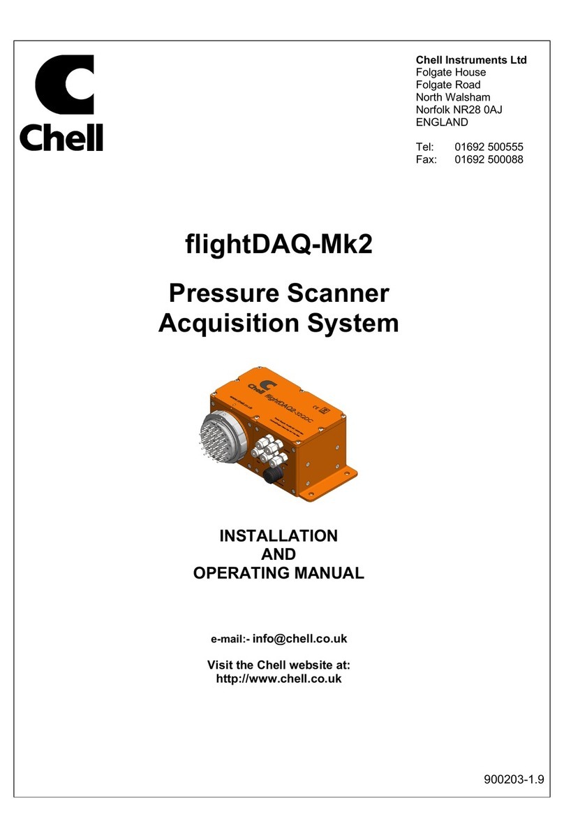
MicroDAQ3
Pressure Scanner
Acquisition System
INSTALLATION
AND
OPERATING MANUAL
900252-1.4

Page 1
Please read this manual carefully before using the instrument.
Use of this equipment in a manner not specified in this
manual may impair the user’s protection.
Chell Document No. : 900252 Issue 1.4
ECO : xxxx Date: 18/01/2023
Chell’s policy of continuously updating and improving products means that this manual may contain
minor differences in specification, components and software design from the actual instrument
supplied.

Page 2
CONTENTS
1 Description ............................................................................................................................. 4
1.1 General ................................................................................................................................................................... 4
2 Specifications ........................................................................................................................ 5
2.1 Ranges .................................................................................................................................................................... 5
2.2 Power Supply: ........................................................................................................................................................ 5
2.2.1 DC Powered Version ...................................................................................................................................... 5
2.2.2 PoE Version .................................................................................................................................................... 5
2.3 CAN specifications: ................................................................................................................................................ 5
2.4 Ethernet Specifications: .......................................................................................................................................... 5
2.5 Environmental specification: .................................................................................................................................. 5
3 Installation and Interconnections ........................................................................................ 7
3.1 Electrical Connections ............................................................................................................................................ 7
3.1.1 64 channel DC Powered Versions - 9-way micro-miniature ‘D’ type (suggested mate : Glenair
MWDM2L-9PS - solder cup version) ............................................................................................................................ 7
3.1.2 64 channel PoE Powered Versions - 9-way micro-miniature ‘D’ type (suggested mate : Glenair
MWDM2L-9SS - solder cup version) ............................................................................................................................ 7
3.1.3 16 channel DC Powered Versions - 9-way micro-miniature ‘D’ type (suggested mate : Glenair
MWDM2L-9SS - solder cup version) ............................................................................................................................ 7
7
3.2 Pneumatic Connections .......................................................................................................................................... 8
3.2.1 64 channel Valved version ............................................................................................................................. 8
3.2.2 64 channel Valved version with quick disconnect plate ................................................................................ 8
3.2.3 64 channel non-Valved version ...................................................................................................................... 8
3.2.4 64 channel non-Valved version with quick disconnect plate ......................................................................... 9
3.2.5 16 channel version .......................................................................................................................................... 9
3.3 Mounting Features ................................................................................................................................................ 10
3.3.1 64 channel Valved Version .......................................................................................................................... 10
3.3.2 64 channel Non-valved Version ................................................................................................................... 10
3.3.3 16 channel Version ....................................................................................................................................... 10
4 Operation of the instrument ............................................................................................... 11
4.1 Connecting up the MicroDAQ3. .......................................................................................................................... 11
4.1.1 DC Powered Versions .................................................................................................................................. 11
4.1.2 PoE Versions ................................................................................................................................................ 11
4.2 Connecting to the MicroDAQ3 ............................................................................................................................ 12
4.2.1 Connecting to the Webserver ....................................................................................................................... 12
4.2.2 Connecting using the MicroDaq-X Software. .............................................................................................. 12
4.2.3 Connecting to Custom Software (Ethernet and CAN) ................................................................................. 12
4.3 Configuring the MicroDAQ3 ............................................................................................................................... 13
4.4 Re-zeroing the MicroDAQ3. ................................................................................................................................ 13
5 MicroDAQ3 Configuration Webserver ............................................................................... 14
5.1 Introduction. ......................................................................................................................................................... 14
5.2 Common Controls Sidebar ................................................................................................................................... 15
5.3 Controls for all variants ........................................................................................................................................ 15
5.4 Controls for valved variant ................................................................................................................................... 15
...................................................................................................................................................................................... 15
5.4.1 The 'Setup Parameters' Page ......................................................................................................................... 16
5.4.2 Introduction .................................................................................................................................................. 16
5.4.3 Data Streaming ............................................................................................................................................. 16
5.4.4 TCP Parameters ............................................................................................................................................ 16
5.4.5 UDP Parameters ........................................................................................................................................... 17
5.4.6 CAN Parameters ........................................................................................................................................... 18
5.5 ‘Live Data’ Page ................................................................................................................................................... 19
5.5.1 ‘Live Data’ Page Valve Position Descriptor ................................................................................................ 20
5.6 ‘Advanced’ Page .................................................................................................................................................. 20
5.6.1 Advanced communication settings ............................................................................................................... 20

Page 3
5.6.2 Miscellaneous ............................................................................................................................................... 22
5.6.3 Zero Coefficients .......................................................................................................................................... 23
5.7 Timestamp ............................................................................................................................................................ 24
6 Timing and The Acquisition Cycle ..................................................................................... 25
6.1 The MicroDAQ3 Acquisition Cycle .................................................................................................................... 25
6.1 Sensor Response Modes ....................................................................................................................................... 25
6.2 The MicroDAQ3 Data Output Cycle ................................................................................................................... 26
6.3 Averaging ............................................................................................................................................................. 26
6.4 Averaging and Time Stamping ............................................................................................................................. 27
7 Hardware Trigger ................................................................................................................. 28
7.1 Hardware Trigger Input. ....................................................................................................................................... 28
7.2 Timing Information .............................................................................................................................................. 28
7.3 Web server control ............................................................................................................................................... 28
7.4 Software Control .................................................................................................................................................. 28
7.5 The Hardware Trigger and System Timing .......................................................................................................... 29
8 Service and Calibration ....................................................................................................... 30
8.1 Service .................................................................................................................................................................. 30
8.2 Calibration ............................................................................................................................................................ 30
8.3 Adjustment ........................................................................................................................................................... 30
8.4 Cleaning ................................................................................................................................................................ 30

Page 4
1 Description
1.1 General
The MicroDAQ3 is a self-contained pressure scanner that acquires and transmits pressure
data to a host via Ethernet or a CAN bus. The MicroDAQ3 fits into the Chell pressure scanner
range alongside the established microDAQ, microCAT and nanoDaq-LT range.
The MicroDAQ3-64 comes in a number of variants; the first of these is the option to include
a purge / calibration valve. The other is the electrical interface which can either be power-
over-ethernet or a conventional DC supply. The microDAQ3-16 is currently only available as
DC. The CAN and hardware trigger features discussed in this manual are only available on
the DC powered versions.
The combination of high-precision digital transducers and Chell’s calibration technology have
resulted in the most accurate and flexible pressure scanners available on the market.
The device has the ability to output absolute pressures or differential pressures by using
additional reference sensors, the 65th and 66th reference channels for the 64 channel variant
and 17th channel for the 16 channel variant.
The MicroDAQ3s are configured using their embedded web-servers. The output stream can
be configured in a number of ways including averaging, transmission speed, absolute or
differential and also the ability to add a time stamp to the data. Compliance with IEEE1588
PTP V2 and a hardware trigger facility give a good level of time determination for the acquired
data.
This manual revision covers microDAQ3-64 firmware version 1.0.9 and microDAQ3-16
firmware version 1.0.4.

Page 5
2 Specifications
2.1 Ranges
The MicroDAQ3 is available in the following ranges:
Differential Range
MicroDAQX
Range
Code (PSI)
Absolute Range
MicroDAQX
Range Code
4” water
1 kPa
0.144509
2.2 to 16.8 psia
15 to 115 kPa
2(a)
10” water
2.5 kPa
0.362173
20” water
5 kPa
0.722541
1 psi
7 kPa
1
1.5 psi
10 KPa
1.5
2.5 psi
17 kPa
2.5
5 psi
35 kPa
5
8 psi
55 kPa
8
1.885 to 23.2 psia
13 to 160 kPa
8(a)
15 psi
103 kPa
15
2.2 to 29.9 psia
15 to 206 kPa
15(a)
30 psi
207 kPa
30
2.2 to 58.01 psia
0 to 400 kPa
45 psi
310 kPa
45
2.2 Power Supply:
2.2.1 DC Powered Version
Line voltage:
8-30 Vdc
Absolute Max. Line voltage
30Vdc
Consumption:
Max 1W (non-valved), 4W (valved version)
2.2.2 PoE Version
PoE Standard:
802.3at Type 1 (Previously 802.3af)
2.3 CAN specifications:
CAN type
2.0B
CAN baudrate
Configurable from 1M, 500K, 125K and 100K.
Programmable variables:
Address 0x?nn
Most significant programmable device ID
Address 0xn?n
Next most significant programmable device ID
BRP
CAN bus timing
TSEG1
CAN bus timing
TSEG2
CAN bus timing
SJW
CAN bus timing
2.4 Ethernet Specifications:
TCP/IP
10Mb/s & 100Mb/s via Auto Negotiation
TCP & UDP protocols supported
2.5 Environmental specification:

Page 6
Operating temperature range:
-40°C to +90°C
Storage temperature range:
-40°C to +90°C
Maximum Relative humidity:
95% at 50°C (non condensing)
Ambient altitude
100 mbar abs or nominally 52000 ft
Vibration
Engine standard vibration test to DO160E category S,
curve W with duration of 1 hr/axis. Fan blade out case
to DO160E category S, curve P.
Fan blade out to DO160F section 7 (40g 11m/s)
Engine load to +/- 40g per axis
Radiated emissions
MIL standard 461-E: RE102
Conducted emissions
MIL standard 461-E/MIL standard 461-C

Page 7
3 Installation and Interconnections
3.1 Electrical Connections
3.1.1 64 channel DC Powered Versions - 9-way micro-miniature ‘D’ type
(suggested mate : Glenair MWDM2L-9PS - solder cup version)
3.1.2 64 channel PoE Powered Versions - 9-way micro-miniature ‘D’ type
(suggested mate : Glenair MWDM2L-9SS - solder cup version)
3.1.3 16 channel DC Powered Versions - 9-way micro-miniature ‘D’ type
(suggested mate : Glenair MWDM2L-9SS - solder cup version)
Pin 1
0v
Pin 2
Ethernet Rx+
Pin 3
CAN Low
Pin 4
Ethernet Tx+
Pin 5
+ Supply (8-25 VDC)
Pin 6
Trigger in (TTL)
Pin 7
Ethernet Rx-
Pin 8
Ethernet Tx-
Pin 9
CAN high
Pin 1
ETH BI_DD+
Pin 2
ETH BI_DA+ (TX+)
Pin 3
n/c
Pin 4
ETH BI_DB+ (RX+)
Pin 5
ETH BI_DC-
Pin 6
ETH BI_DD-
Pin 7
ETH BI_DA- (TX-)
Pin 8
ETH BI_DB- (RX-)
Pin 9
ETH BI_DC+
Pin 1
0v
Pin 2
Ethernet Rx+
Pin 3
CAN Low
Pin 4
Ethernet Tx+
Pin 5
+ Supply (8-25 VDC)
Pin 6
Trigger in (TTL)
Pin 7
Ethernet Rx-
Pin 8
Ethernet Tx-
Pin 9
CAN high

Page 8
3.2 Pneumatic Connections
3.2.1 64 channel Valved version
3.2.2 64 channel Valved version with quick disconnect plate
3.2.3 64 channel non-Valved version

Page 9
3.2.4 64 channel non-Valved version with quick disconnect plate
3.2.5 16 channel version
Hot plugging the power to the MicroDAQ3 at the connector can cause permanent
damage to the unit. Always switch the power at the power supply source.

Page 10
3.3 Mounting Features
3.3.1 64 channel Valved Version
3.3.2 64 channel Non-valved Version
3.3.3 16 channel Version
There are no mounting features on the microDAq3-16

Page 11
4 Operation of the instrument
4.1 Connecting up the MicroDAQ3.
The MicroDAQ3-64 can be supplied in DC powered versions complete with CAN and
hardware trigger or power-over-ethernet (PoE) versions for units that incorporate the valve
option. Currently the MicroDAQ3-16 is only available as a DC version, which includes CAN
and hardware trigger.
4.1.1 DC Powered Versions
The MicroDAQ3 has a single connector, the cable which supplies the unit with power also
provides CAN and Ethernet comms. Ensure all the connections are made before powering
up the MicroDAQ3.
The MicroDAQ3 can be supplied with a cable and interface (MicroDaq-INT) to make
connection to the units straight forward. In this case, connect the cable to the MicroDAQ3
and interface and then power the unit with the plug-in DC supply (12 Vdc) that is supplied
with the interface. The Ethernet connection can be made directly from a PC or hub / switch
to the RJ45 incorporated in the MicroDaq-INT.
Alternatively, a user can make their own cable that brings out the Ethernet and DC supply to
their own power supply. Care should be taken that the connection are correct or the unit may
be damaged.
Upon power up, the blue LED will light constantly while the MicroDAQ3 boots up. This will
typically take around 2 seconds. When the MicroDAQ3 has finished booting, the blue LED
will flash at a constant rate to show that the system is running (unless auto hardware trigger
enable has been set – see later).
4.1.2 PoE Versions
When using the MicroDAQ3 PoE version, all that is required is to plug the unit into a PoE
enabled ethernet switch. The MicroDAQ3 will then negotiate with the switch so that
sufficient power is supplied to the unit.

Page 12
4.2 Connecting to the MicroDAQ3
Once the blue LED is flashing, the microDAQ3 can be connected to by any one of the following
methods.
[1] By using Ethernet and the embedded web server
[2] By using Ethernet and the Chell MicroDaqX software
[3] By using Ethernet and custom software
[4] By using CAN and custom software
4.2.1 Connecting to the Webserver
To connect to the internal web server, simply connect the MicroDAQ3 to a suitable PC and simply
type the IP address of the MicroDAQ3 (found on the label) into a web browser. The web server will
allow you to read data (both absolute and differential) as well as view all the configuration options
available on the microDAQ3.
We have found that the best results are achieved with the Firefox web browser but it will also
work with Edge, Chrome and Safari. We do not recommend using Internet Explorer as we
have come across settings options errors with this web browser.
For a PC to successfully connect over Ethernet, the first three parts of the IP address must be the
same on the MicroDAQ3 and the PC that is making the connection. For example, if the IP address
of the MicroDAQ3 is 192.168.1.190, the PC must have an IP of 192.168.1.XXX. Once connection
has been made, the IP address can be changed to suit the user’s network.
NOTE. If the IP or subnet mask of the MicroDAQ3 is changed, it must be recorded (we recommend
that it is written on a new label) as it will not be possible to connect to the MicroDAQ3 if these details
are not known. In this instance, the MicroDAQ3 will need to be returned to the factory so the IP
address can be reset.
4.2.2 Connecting using the MicroDaq-X Software.
Chell supply the MicroDaqX software free of charge which can be used to view data and save it to
disk. It also allows many of the run time configuration settings to be adjusted (such as re-zero and
hardware trigger control). See the MicroDaqX manual for further information (900170-X.X).
When using high data rates, Windows® may require some registry modifications to enable the
higher speeds. Please refer to section 4.1.4 in the MicroDaq2 and flightDaq2 user programming
guide (900204-X.X) for further details.
4.2.3 Connecting to Custom Software (Ethernet and CAN)
The full command structure for both the Ethernet (TCP and UDP) and CAN may be found in the
MicroDAQ3 user programmers guide (900253-X.X).

Page 13
4.3 Configuring the MicroDAQ3
The MicroDAQ3 is designed to be configured via the embedded web server. Here all the
product variables may be changed including IP address, CAN ID, averaging, transmission
speed etc. Once these setting are configured, they can be permanently saved by clicking on
‘BURN TO EEPROM’. Once the unit is reset, the MicroDAQ3 will run using these setting.
The MicroDAQ3 can be configured to output data over CAN or Ethernet (TCP/IP or UDP)
and, if configured to do so, it will output this data immediately upon power up. The MicroDAQ3
can also accept commands over the Ethernet or CAN networks to configure the majority of
the internal setting (with the exception of CAN ID, IP address and some lower level functions).
Please refer to document 900253 – MicroDAQ3 user programming guide for available CAN
and Ethernet commands and the format of the data output stream.
4.4 Re-zeroing the MicroDAQ3.
It is possible to re-zero the output of the MicroDAQ3 for either absolute or differential
measurements. This may be necessary if the unit is not sufficiently warmed up or has been
subjected to a severe thermal gradient.
The MicroDAQ3 is re-zeroed by sending the appropriate command over the CAN or Ethernet
link via the Chell software or via the embedded webserver. The system will then average a
number of zero readings and perform a re-zero. Naturally, there should be no pressure
applied to the ports of the scanner when a re-zero is being performed.
When a re-zero is being performed, the red LED will light momentarily. The re-zero value is
not stored in volatile memory and will be lost upon reset. By default, the re-zero values are
volatile and lost with a power cycle - see section 5.7.3 for permanently saving the zero values
if necessary.

Page 14
5 MicroDAQ3 Configuration Webserver
5.1 Introduction.
The MicroDAQ3 web Configuration provides the means of setting up and demonstrating the
MicroDAQ3 unit from a standard PC with an Ethernet port and browser.
The webserver is divided by tabs into five areas of functionality, namely 'Setup’, 'Live Data',
‘Advanced’, ‘Timestamp’ and ‘Factory Tools’.
'Setup Parameters' provides the means to set MicroDAQ3’s main operating parameters
such as data streaming rates and Device addresses.
The unit's function may be checked and demonstrated using 'Live Data' to show the
MicroDAQ3’s calibrated output.
‘Advanced’ provides setup for the all other more advance parameters that may require
setting on a per application basis.
‘Timestamp’ provides some options for configuring the timestamping feature of the
MicroDAQ3.
‘Factory Tools’ provides some functionality to change the MAC address of the Ethernet
hardware. This tab is password protected and therefore not readily available to everyone and
further detail is beyond the scope of this document.
Figure 5.1, Main Setup page of valved unit variant

Page 15
5.2 Common Controls Sidebar
5.3 Controls for all variants
Figure 5.1 above shows the first page viewed when navigating to the
webserver. It includes the common controls sidebar, shown in figure 5.2,
and the main group of setup parameters. The sidebar provides information
on the MicroDAQ3 unit including serial numbers and current firmware
revision along with the configured scanner full scales and total channels.
The function of the common controls is detailed in the subsequent table
(Table 5.1)
Table 5.1, Common sidebar control functions.
Figure 5.2, Sidebar
5.4 Controls for valved variant
Figure 5.3 shows the sidebar panel of a valved MicroDAQ3 unit, it
contains the same standard controls as described in the previous section
with the addition of two additional controls for placing the device into its
calibration mode and into standard operating mode.
Table 5.2, Valved variant specific sidebar control functions
Control
Function
'RESET' button
Resets the MicroDAQ3, similar to power cycling the device. Use to
activate new settings and/or rebuild calibration tables.
'Rezero' button
Starts a MicroDAQ3 rezero operation.
‘Burn to eeprom”
button
Burns all changes made to the local settings into the eeprom so they
can be retrieved upon restart.
Control
Function
'Run Position'
button
Moves the internal shuttle valve so that all measurement ports are
connected to each transducer.
'Purge/Cal Position'
button
Moves the internal shuttle valve so that all transducers are connected
to the ‘cal’ port and all measurement ports are connected to the purge
ports.
Figure 5.3, Valved Variant Sidebar

Page 16
5.4.1 The 'Setup Parameters' Page
5.4.2 Introduction
The 'Setup Parameters' page shows all of the MicroDAQ3’s main operating parameters.
Setup Parameters is divided into different categories by function, and each category is
detailed separately in the following.
5.4.3 Data Streaming
The ‘Data Streaming’ section allows the user to change settings that affect all three
communication protocols, and allows the user to choose the protocol that is to be used, along
with the data transfer rate.
Figure 5.4, Data Streaming group
Control
Function
‘Comms Protocol’ radio button
Chooses the communication protocol that is to be used. This button changes what
options are available below it.
‘Data Rate’ option list
Selects the rate at which the MicroDAQ3 will automatically transmit data after reset.
The maximum data rate available will be dependent on the sensor response setting
is selected on the Advanced settings tab.
‘Protocol’ option list
Selects the format that the data will be transmitted as, options are 16 bit LE, and16
bit BE which will apply to all protocols.
‘Apply’ button
Applies the changes made to the local settings memory.
Pressure Input Average Samples
Displays the number of samples used for deriving the average pressure.
Table 5.3, Data Streaming settings.
It should also be noted that changing the data rate also changes the Pressure input averaging
samples to optimum settings based on the requested data rate.
The maximum measurements per sensor is determined by the sensor response setting that
is used, data rates up to and including the selected sensor response frequency may be used.
5.4.4 TCP Parameters
The TCP communication protocol parameters are shown in Figure 5.5. This only shows if the
TCP radio button is selected in the data streaming section. The options in this section control
the MicroDAQ3’s IP address, subnet mask and Local port.

Page 17
Figure 5.5, TCP Comms group
'IP Address'
IP address allocated to MicroDAQ3 on the user's network.
'Subnet'
Subnet mask as set on the user's network.
‘Local port’
Local port of the device.
‘Apply TCP’
Applies the settings to the local memory
Table 5.5, TCP Comms group settings
5.4.5 UDP Parameters
The UDP section (figure 5.6) holds all the settings specific to UDP. In UDP mode each
acquisition cycle (of ‘x’ number of channels) is packed as a separate UDP packet with a four-
byte representation of the MicroDAQ3 serial number at the start of the packet. These are
attempted to be sent out at the required rate but with no checking for reception or validity of
data.
It is also possible to change the output data packet format to IENA specification format by
using the check box.
Note that the MicroDAQ3’s local IP address is the same setting as from the TCP Comms
group.
Figure 5.6, UDP Comms group
‘Local IP address and subnet’
This displays the IP address of the MicroDAQ3, this is the same as in the TCP comms
section.
‘Local port’
Local port of the device.
‘Remote UDP IP address’.
Address of remote connection to MicroDAQ3. If set then the MicroDAQ3 can be set to
auto stream data to that remote host on boot up (after initialisation)
‘Remote UDP port.’
Port of remote connection to MicroDAQ3. If set then the MicroDAQ3 can be set to
auto stream data to that remote host on boot up (after initialisation)

Page 18
‘Use IENA Specification for data
stream’
Changes the format of data output packets to IENA specification.
‘Apply’
Applies the settings to the local settings memory
Table 5.6, UDP Comms group settings
5.4.6 CAN Parameters
The CAN communication settings are shown in Figure 5.7. Options are available to set the
base message ID number may be selected, and the offset from this base number for the
reception of user commands over CAN, and whether an acknowledgement of these user
commands is sent on the next higher message number. Data may be transmitted on either
multiple messages, or alternatively on a single message ID, with a selectable delay between
messages.
Figure 5.7, CAN Comms group
‘CAN First TX Message ID’
MicroDAQ3 uses standard CAN message arbitration id’s, and the unit is assigned the
most significant 2 digits of the Hex base address. For the digits 0x1A0 for example,
data for the first 4 channels will be sent on 0x1A0, the next 4 on 0x1A1, etc.
Message scheme/delay
Select ‘Multiple Messages’ for the 4 channels per message, multiple message
scheme. Alternatively, data may be packed 3 channels per message + identifier byte,
with a selectable delay between messages.
‘CAN RX ID Offset’
Selects the hex offset from the base message ID where MicroDAQ3 will receive
incoming user commands (see user command document). If ‘Ack. Enabled’ is
selected, the unit will acknowledge the reception of a correctly formatted command on
the message ID calculated as Base ID + RX Offset + 1
‘Apply’
Applies the settings to the local settings memory
Table 5.7, CAN Comms group settings.

Page 19
5.5 ‘Live Data’ Page
Figure 5.8 shows the 'Live Data' page of the webserver.
Figure 5.8, 64 channel Live Data Page – differential measurements
Figure 5.8, 64 channel Live Data Page – absolute measurements
The live data page is a means to demonstrating the correct operation of MicroDAQ3 and
testing the unit's calibration. A value label is shown for each channel with 1-64 (1-16 for the
16 channel variant) for both the temperature and the pressure data.
There is also both of the reference channels pressure and temperature value at the bottom
of the page (a single reference for the 16 channel variant).
The pressure data can be in either BAR, PSI or Pa (Pascals), this is decided on the advanced
page, but is displayed on the top right of the live data page for convenience.
Table of contents
Other Chell Scanner manuals
Popular Scanner manuals by other brands
Ricoh
Ricoh G413 Supplemental operating instructions

Stratford Labs
Stratford Labs EasyScan ES-01 user manual

Epson
Epson GT-15000 Series Operation user's manual

Canon
Canon CANOSCAN FB330 series Service manual
Digital Check
Digital Check SmartSource SSM1-ELITE55-IJ Installation and operation guide

Evixscan 3D
Evixscan 3D HD Optima user manual
