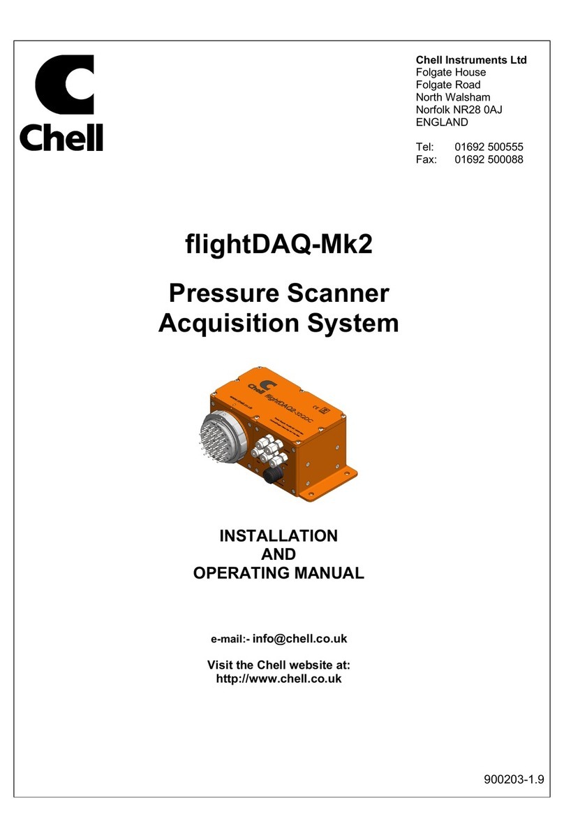
Chell microDAQ-Mk2 Operating instructions

Chell Instruments Ltd
Folgate House
Folgate Road
North Walsham
Norfolk NR28 0AJ
ENGLAND
Tel: 01692 500555
Fax: 01692 500088
MicroDaq-Mk2
Covering MicroDaq2,
FlightDaq2, CANdaq5 and
FlightDAQ-TL
USER PROGRAMMING
GUIDE
e-mail:- info@chell.co.uk
Visit the Chell website at:
http://www.chell.co.uk
900204-1.7

Please read this manual carefully before using the instrument.
Use of this equipment in a manner not specified in this
manual may impair the user’s protection.
Chell Document No. 900204 : Issue 1.7
ECO: 3802 Date: 16th June 2020
Chell’s policy of continuously updating and improving products means that this manual may contain minor

1. Introduction. .......................................................................................................................... 1
2. User Command Protocol. ....................................................................................................... 2
2.1. Command Packet.......................................................................................................................... 2
2.2. Acknowledgement........................................................................................................................ 2
2.3. User Commands. .......................................................................................................................... 2
3. Status Data Format. .............................................................................................................. 6
3.1. MicroDaq & FlightDaq .................................................................................................................. 6
3.2. FlightDaq-TL ................................................................................................................................. 6
4. Communication Channels. ..................................................................................................... 7
4.1. TCP ............................................................................................................................................... 7
4.1.1 Overview. .................................................................................................................................................... 7
4.1.2 Connection. ................................................................................................................................................. 7
4.1.3 TCP Protocol. ............................................................................................................................................... 7
4.1.4 TCP Data Rate. ........................................................................................................................................... 10
4.1.5 Control Via TCP. ......................................................................................................................................... 10
4.2. UDP ............................................................................................................................................ 11
4.2.1 Overview ................................................................................................................................................... 11
4.2.2 Connection ................................................................................................................................................ 11
4.2.3 Chell UDP Protocol ..................................................................................................................................... 11
4.2.4 UDP Data Rate. .......................................................................................................................................... 13
4.2.5 Control Via UDP. ........................................................................................................................................ 13
4.3. Timestamping ............................................................................................................................. 14
4.4. IENA specification ....................................................................................................................... 14
4.5. CAN ............................................................................................................................................ 16
4.5.1 Overview ................................................................................................................................................... 16
4.5.2 CAN Baudrate ............................................................................................................................................ 16
4.5.3 CAN Protocol ............................................................................................................................................. 16
4.5.4 CAN Data Rate ........................................................................................................................................... 18
4.5.5 Control Via CAN ......................................................................................................................................... 18
4.6. Internal RAM .............................................................................................................................. 19
4.6.1 Overview ................................................................................................................................................... 19
4.6.2 Internal RAM Protocol ................................................................................................................................ 19
4.6.3 Internal RAM Data Rate ............................................................................................................................. 19
4.6.4 Internal RAM Dump ................................................................................................................................... 19
5. Valve Control user commands ................................................................................................... 21

Page 1
1. Introduction.
This manual covers the microDAQ (Mk2), flightDAQ (Mk2) and flightDAQ-TL products. The communication
protocol is common across all ranges although not all options are available for all products.
The manual specifically refers to the microDAQ product although this applies to all the products listed above.
From power up, the microDAQ reads its non volatile setup information and calibration, and after applying
these settings is then ‘up and running’, reading the scanner/transducers and delivering calibrated data.
Although for many applications this is enough, more demanding applications may need to control the data
delivery, request data rezero operations and more.
The microDAQ-Mk2 has the same user interface protocol taken from the microDAQ system, allowing remote
access to the essential commands required when integrating the unit into an instrumentation system.
Commands may be sent over any of the unit’s communication channels, whether the current active data
channel or not. A simple block parity check adds security to the command protocol, and a correctly received
command may be acknowledged if required.
The following sets out the essentials of the command protocol, the data packet format for all channels in
addition to the message identifier arrangement for the CAN channel.
This document also details the user commands for valve controls that are found in the flightDAQ and the
microQDVP module which use the same command protocol.
This document version supports V2.0.4 of the microDAQ-Mk2 firmware, V2.0.10 of the flightDAQ firmware
and V1.0.0 of the flightDAQ-TL firmware. If using earlier firmware then some user commands and/or
parameters may be invalid.

Page 2
2. User Command Protocol.
2.1. Command Packet.
The command protocol is based around a simple delimited control packet, allowing easy identification of
command start and end. The packet includes a block parity byte increasing the robustness of transmission;
the packet format is shown in Figure 2.1.
> (ASCII 62)
Command
Parameter
Parity
< (ASCII 60)
Figure 2.1 Command Frame Format.
The command byte values are defined in the following section, and may or may not require a parameter byte,
for example data rate. The parity byte is an even block parity of all bytes (other than itself), including the
delimiters. Calculation for parity bit n is therefore the sum of each bit n using modulo 2 arithmetic.
For a command not requiring a parameter, an arbitrary dummy byte should be used. This can be any value as
the number is not processed other than in determining the parity of the command packet.
2.2. Acknowledgement.
A command packet is positively acknowledged if it is correctly formatted and the parity byte is correct. A
positive acknowledgement is denoted by the transmission of ASCII 42 ('*'), a negative acknowledge indicating
an invalid command by ASCII 33 ('!'). Recognised command values are then acted upon, though unrecognised
values are discarded.
2.3. User Commands.
The available user command set is summarised in Figure 2.2.
Command (*
DTC only)
Byte,
Char/
ASCII
Parameter
Description
Standby
S/83
None
Set all data streaming off.
Reset
R/82
None
Request a soft device reset - microDAQ is reinitialised.
Rezero
Z/90
0: All channels
1 to 32: rezero specified
channel
Request a rezero.
Channel parameter is only supported on the flightDAQ-TL models,
where no parameter is specified a ‘0’ is implemented.
Derange *
D/68
None
Calibration is rebuilt with the appropriate deranging factor applied, the
DTC scanner deranging gain is switched into circuit. This command is
not valid for flightDAQ-TL.
Rebuild
Calibration
C/67
None
The calibration is rebuilt for the current temperature, using the active
microDAQ settings. This command is not valid for flightDAQ-TL.
Rezero and
Rebuild
G/71
None
Requests a rezero followed by a calibration table rebuild, with the
calculated zero offsets being applied to the calibration data.. Note
these rezero offsets are separate from any normal rezero that may be
performed afterwards. This command is not valid for flightDAQ-TL.

Page 3
Rate
V/86
byte = 0xab
a = 1 TCP / UDP
a = 2 CAN
a = 3 Internal RAM
For TCP / UDP:
b = 0 : Off
b = 1 : 1000Hz
b = 2 : 625Hz
b = 3 : 500 Hz
b = 4 : 400 Hz
b = 5 : 312 Hz
b = 6 : 225 Hz
b = 7 : 200 Hz
b = 8 : 150 Hz
b = 9 : 100 Hz
b = 10 : 50 Hz
b = 11 : 25 Hz
b = 12 : 20 Hz
b = 13 : 10 Hz
b = 14 : 5 Hz
b = 15 : 1 Hz
For CAN & Internal
RAM:
b = 0 : Off
b = 1 : 1000 Hz
b = 2 : 750 Hz
b = 3 : 625 Hz
b = 4 : 500 Hz
b = 5 : 312 Hz
b = 6 : 100 Hz
b = 7 : 50 Hz
b = 8 : 25 Hz
b = 9 : 10 Hz
b = 10 : 5 Hz
b = 11 : 2 Hz
b = 12 : 1 Hz
flightDAQ-TL TCP/UDP
b = 0 : Off
b = 1 : n/a (250Hz)
b = 2 : n/a (250Hz)
b = 3 : n/a (250Hz)
b = 4 : n/a (250Hz)
b = 5 : 250 Hz
b = 6 : 200 Hz
b = 7 : 150 Hz
b = 8 : 100 Hz
b = 9 : 50 Hz
b = 10 : 33 Hz
b = 11 : 25 Hz
b = 12 : 20 Hz
b = 13 : 10 Hz
b = 14 : 5 Hz
b = 15 : 1 Hz
Adjust the data delivery rate for each communication channel. The
upper nibble of the parameter byte selects which communication
channel, while the lower selects its data rate.
CAN & Internal RAM ‘comms’ have the same available data rates. CAN
& RAM commands are not supported on flightDAQ-TL
Protocol
P/80
byte = 0xab
a = 1: TCP / UDP
a = 2 :CAN
Permits the changing of the data protocol. The abbreviations LE and BE
in the table refer to little and big endian respectively, denoting whether
the less significant byte is sent first or last.

Page 4
b = 0 : 16 bit LE
b = 1 : 16 bit BE
b = 2 : Engineering
Units
b = 3 : 32 bit LE
b = 4 : 32 bit BE
Pressure data is available in engineering units over UDP, TCP and RS232
connections, though only binary data is available with CAN and Internal
RAM.
flightDAQ-TL only supports TCP and UDP.
Binary data provides pressure scaled as unsigned integers to the
operating full scale, eg for 16 bit resolution, 0 to 65535 represents -FSD
to +FSD.
Stream ON
1/49
1 – TCP / UDP
2 - CAN
3 - Internal RAM
4 - Internal RAM (stop
on full)
Enable the data delivery for the chosen channel. The delivery rate is as
selected in microDAQ Setup, unless it is modified via the Rate
command.
Internal RAM data streaming will either log continuously, wrapping
when the end of available RAM is reached, or will stop when the RAM
is full, depending on parameter.
flightDAQ-TL only supports TCP and UDP
Stream OFF
0/48
1 - TCP / UDP
2 - CAN
3 - Internal RAM
Disable the data delivery for the chosen channel.
flightDAQ-TL only supports TCP and UDP
Get Status
?/63
0 : Short
1 : With temp.
2 : Full
3 : Pressure reading
4 : Temp. readings
5 : Excitation reading
6 : Hall sensor read
7 : Firmware ID
8 : Unit serial number
9 : Scanner serial
number
For flightDAQ-TL
0 : Short
1 : Internal pressure
and temperature
2 : Full
3 : undefined
4 : undefined
5 : Excitation reading
6 : Sensor type
7 : Firmware ID
8 : Unit serial number
9 : Connector serial
numbers
Return a status packet from the microDAQ. Three main versions are
available, 'short', 'with temp.' and 'full'. Short returns status byte
information showing current operating state only, whereas 'full' returns
microDAQ setup options and temperature data in addition. 'With
temp.' returns the status and temperature information intended for
continuous temperature monitoring applications. The data format is
documented in a separate section.
Additional readings poll raw values for temperature and pressure as
read from the scanner, as well as other fields as indicated in the table
The flightDAQ-TL responds in a different manner to the microDAQ and
flightDAQ.
Channels
H/72
byte = 0xab
a = 1 TCP / UDP
a = 2 CAN
a = 3 Internal RAM
b = 0 - 16
b = 1 - 32
b = 2 - 48
b = 3 - 64
Set the number of active channels returned to the user for a data
channel. Setting a value greater than the current system maximum
channels (set via setup/dtc scanner read or by the Maximum Channels
command) results in the maximum channels value being used.
For flightDAQ-TL channels 1-16 are primary channels, 17-32 are
secondary channels.
flightDAQ-TL does not support CAN or RAM
Maximum
Channels
M/77
0 - 16
1 - 32
2 - 64
Set the system maximum channels, ie the number of channels read
from the scanner. Allows the dynamic alteration of the effective per
channel sampling rate. This command is not valid for flightDAQ-TL

Page 5
Poll
O/79
1 - TCP / UDP
2 – CAN
Request a single data packet (in the current active format) for the
channel selected. Data streaming should be set off before using this
command. Note that there is no positive acknowledge for this
command. This command is not valid for logging to Internal RAM. CAN
is not supported on flightDAQ-TL
Span
A/65
None
Request a ‘span’ operation. The unit should have been recently
rezeroed, then the appropriate span pressure (as selected from the
setup software) applied to the scanner. Requesting a span operation
will then calculate the span correction coefficient for each channel. All
rezero values and span coefficients are then written to the unit’s
EEPROM (NOT to the scanner), and the calibration tables rebuilt using
these new values.
Reset Linear
Calibration
E/69
None
Resets the linear calibration (ie zero and span values) held within the
unit to 0 and 1.0 respectively for all channels. A calibration table rebuild
is then performed.
Hardware
Trigger
T/84
byte = 0xab
a = 0 Disable
a = 1 Enable
b = 1 TCP / UDP
b = 2 CAN
b = 3 Internal RAM
b = 4 Internal RAM
(stop on full)
Enables or disables the hardware trigger on the selected channel. Note
that there is no positive acknowledge for this command.
Assuming a valid hardware trigger is detected for the duration, Internal
RAM data streaming will either log continuously, wrapping (and
therefore overwriting) when the end of available RAM is reached, or
will stop when the RAM is full (and automatically disable the hardware
trigger), depending on the parameter.
flightDAQ-TL does not support hardware trigger.
Start Internal
RAM Dump
I/73
1 - TCP / UDP
2 - CAN
Starts the internal RAM dump, sending data using the comms channel
chosen by the parameter. The first packet is sent immediately and
consists of a 9 byte header (only 6 bytes for CAN - see later). This
command is not valid for flightDAQ-TL
Internal RAM
Dump
Handshake
J/74
None
Handshake command to indicate previous packet was received. Must
be sent after header packet & all subsequent data packets. This
command is not valid for flightDAQ-TL
Figure 2.2, The Available User Command Set for the microDAQ.

Page 6
3. Status Data Format.
3.1. MicroDaq & FlightDaq
Status data is not currently supported over the CAN channel, however for TCP connections, status data may
be requested from the microDAQ as three forms – ‘short’, ‘full’ and ‘with temp’. The short form returns 4
bytes, the 16 bit status word delimited by the ASCII characters ">" and "<", the less significant byte is returned
before the more significant. The bit assignment is shown in figure 3.1.
15
I-daq
conn.
Hardware
Trigger
Active
Derange
acvtive
DTC
conn.
CAN
Active
TCP
Active
Reserv
ed
Cal.
table
Span
Rezero
Figure 3.1, Status word bit assignment.
Requesting the status 'with temp.' returns the short status 4 bytes, followed by the temperature data. For a
non DTC scanner, a single value (ASCII unsigned 14 bit) representing the read temperature voltage is appended
to the status bytes. For a DTC application, all active channels are returned in ascending order as comma
delimited ASCII engineering units (ie degrees C).
The 'full' status data contains the above, followed by fields for the setup options of the microDAQ. Each field
is comma delimited, and its function is indicated in plain text between square parentheses. On/off is indicated
by 1/0. An example 'full' status string is shown in figure 3.2 for a microDAQ with a non DTC scanner. Note that
the figure for full scale includes the derange constant (ie scanner full scale x derange constant) if the derange
option has been selected in setup.
Figure 3.2, Full status information.
3.2. FlightDaq-TL
Status data is currently not defined . .
*>Mó<8198,[Full scale] 15.00000000,[Active channels] 32,[DTC active] 0,[CAN
channels] 32,[TCP channels] 32,[CAN rate] OFF,[TCP rate] OFF,[CAN protocol] 16 LE,[TCP
protocol] 16 LE,[Press. input impulse] 1,[Temp. input impulse] 0,[Press. input power]
3,[Temp. input power] 0,[Press. output power] 0,[Reset on delivery] 0,[Temp.
compensation] 0,[Period] 10m,[IP] 0.0.0.0,[Mask] 0.0.0.0,[Gateway] 0.0.0.0,[CAN
timing] (BRP) 5 (TSEG1) 2 (TSEG2) 0 (SJW) 1,[CAN message] 00n,[Rezero order] 4,

Page 7
4. Communication Channels.
4.1. TCP
4.1.1 Overview.
The microDAQ’s TCP channel affords it the ability to stream real time data at high speed over standard 100Mbit
Ethernet connections.
4.1.2 Connection.
When using the TCP/IP channel, the microDAQ is programmed to listen on its local port number 101. It will
respond to a connection request, connect and immediately start streaming data if it has been setup to use the
TCP channel. Note that the microDAQ only supports one TCP connection.
Setup requires the microDAQ to be given an IP address, and the network’s subnet mask. It is possible either
to run the microDAQ over a local Ethernet connection, or directly from a PC’s network card, as long as a
crossover cable is used. A dual network card (or 2 cards) may be used, however care should be taken about
network routing, as similar subnets for two network connections on a single Windows ® machine can cause
the microDAQ not to be seen on the second card. The microDAQ will respond to a ‘ping’ instruction for the
purposes of setup and troubleshooting.
4.1.3 TCP Protocol.
With TCP channel selected calibrated pressure data are streamed continuously over the TCP interface.
Depending on the device variant, TCP supports a range of different data formats as shown in Figure 4.1. The
binary data formats scale the data to 0 to 65535 bits which represent either -/+ full scale respectively (IEEE
754 representation for 32 bit). Binary protocols require less communications bandwidth as well as less
processor overhead within the microDAQ; it is recommended that engineering unit conversions be applied at
the client. Note that the flightDAQ-Mk2 can be configured to stream absolute or differential pressure channel
data. When configured for absolute pressure, the binary representation is 0 bits = approx. 2 psi (15000Pa) &
65535 bits = approx. (scanner full scale value + 15psi). E.g. for a 15psi scanner, 65535 bits = 30psi (or more
precisely 207000Pa). Note: The current firmware release (V2.0.10) currently supports absolute representation
for 2psi, 8psi and 15psi fullscales only – more will follow in future firmware releases.
In the case of the TCP channel, the engineering unit protocol should be avoided if possible, due to the need to
declock the microDAQ’s internal clock and scanner addressing to half of the chosen acquisition rate (due to
internal issues regarding string handling). The 16 bit little ended protocol is most efficient from the
microDAQ’s viewpoint, the data being calibrated and spanned to 0 to 65535 (zero at 32767). Scaling to floating
point full scale is better achieved within a PC client application where there is more processing power
available.
16bit, little endian (microDAQ-Mk2)
Header
Channel1 Data
Channel 2 Data
Channel 3 Data
0x00
0xFF
0x00
LSB
MSB
LSB
MSB
LSB
MSB
….
Channel ’N’ Data
LSB
MSB
3 byte header identifies the start of the packet, followed by all channels (1 to ‘N’ where ‘N’ = 16, 32 or
64 depending on setting), LSB first, with no delimiters.

Page 8
16bit, big endian (microDAQ-Mk2)
Header
Channel1 Data
Channel 2 Data
Channel 3 Data
0x00
0xFF
0x00
MSB
LSB
MSB
LSB
MSB
LSB
….
Channel ’N’ Data
MSB
LSB
3 byte header identifies the start of the packet, followed by all channels (1 to ‘N’ where ‘N’ = 16, 32
or 64 depending on setting), MSB first, with no delimiters
16bit, little endian (flightDAQ-Mk2)
Header
Abs sensor Data
Channel 1 Data
Channel 2 Data
0x00
0xFF
0x00
LSB
MSB
LSB
MSB
LSB
MSB
….
Channel ’N’ Data
LSB
MSB
3 byte header identifies the start of the packet, followed by 16bit representation of absolute pressure
sensor (0 to 65535 bits = 15000Pa to 115000Pa), followed by all channels (1 to ‘N’ where ‘N’ = 16, 32
or 64 depending on setting), LSB first, with no delimiters
16bit, big endian (flightDAQ-Mk2)
Header
Abs sensor Data
Channel 1 Data
Channel 2 Data
0x00
0xFF
0x00
MSB
LSB
MSB
LSB
MSB
LSB
….
Channel ’N’ Data
MSB
LSB
3 byte header identifies the start of the packet, followed by 16bit representation of absolute pressure
sensor (0 to 65535 bits = 15000Pa to 115000Pa), followed by all channels (1 to ‘N’ where ‘N’ = 16, 32
or 64 depending on setting), MSB first, with no delimiters
32bit IEEE754 float, little endian (flightDAQ-TL)
a) TCP
Header
Channel1 Data
Channel 2 Data
Channel 3 Data
0x00
0xFF
0x00
LSB
MSB
LSB
MSB
LSB
MSB
….
Channel ’N’ Data
LSB
MSB
3 byte header identifies the start of the packet, followed by all channels (1 to ‘N’ where ‘N’ = 16, 32 or
64 depending on setting), LSB first, with no delimiters
32bit IEEE754 float, big endian (flightDAQ-TL)
a) TCP
Header
Channel1 Data
Channel 2 Data
Channel 3 Data
0x00
0xFF
0x00
MSB
LSB
MSB
LSB
MSB
LSB
….
Channel ’N’ Data
MSB
LSB
3 byte header identifies the start of the packet, followed by all channels (1 to ‘N’ where ‘N’ = 16, 32 or
64 depending on setting), MSB first, with no delimiters
ASCII comma separated (all variants)
Hdr
Channel 1 Data
Channel 2 Data
….
Channel ‘N’ Data
*
,
#.######
,
#.######
,
,
#.######

Page 9
Single character header followed by all channels (1 to ‘N’ where ‘N’ = 16 or 32 depending on setting),
5 decimal places, comma delimited. (flightDAQ-TL returns 6 decimal places). Note that flightDAQ-Mk2
includes the Abs sensor data in the same format, comma separated, just before Channel 1 Data.
Figure 4.1, Data Packet Protocol, TCP Channel.

Page 10
4.1.4 TCP Data Rate.
The data delivery rate is selected from the setup program, the available rates vary depending on the product
type, see the RATE command in Section 2.3. Although the system endeavours to deliver the rate with
maximum accuracy, ultimate responsibility for data timing lies with the user’s host system.
When using microDAQ or flightDAQ products with pressure scanners, note that since the scanners are
addressed at a fixed channel rate (20kHz if configured for Gen1 scanners, 50kHz if configured for Gen2
scanners), requesting a data delivery of more than 20k/No. Channels (Gen1) or 50k/No. Channels (Gen2) - i.e.
312Hz for a 64 channel Gen 1 scanner) - wastes resources and in some cases can actually cause the microDAQ
to hang and require a power cycle.
The data rate over TCP is vulnerable to low level operating system considerations, in particular any ‘delayed
acknowledgement’ algorithm. Windows ® attempts to suppress too many acknowledgments for small data
packets swamping a network by inserting a 200ms (default) delay in the generation of a second
acknowledgement to a communicating device. Since the microDAQ’s communication consists of many small
packets at a high repeat rate, this algorithm has a catastrophic effect on the microDAQ’s delivered bandwidth
(effectively limiting it to tens of Hz).
The bottleneck can be removed by altering/adding a value of the registry key:
HKLM\System\CurrentControlSet\Services\Tcpip\Parameters\Interfaces\{adapter GUID}
(HKLM = HKEY_LOCAL_MACHINE; {adapter GUID = the network adapter being used by the Windows PC),
though this should be done only in consultation with the network administrator.
In Windows 2000, the DWORD value TcpDelAckTicks should be set to 0 in the registry key.
In Windows XP (must have SP1 or later installed), the DWORD value TcpAckFrequency should be set to 1 in
the registry key.
Also note that the TCP channel of the microDAQ is subject to buffering both within the unit itself (the size of
the buffer depending on number of channels and data rate), and within Windows ® itself. At low data rates,
it is possible to receive single complete data packets, however as the data rate increases Windows ® is more
likely to deliver chunks of data 2k to 4k bytes in length, with arbitrary boundaries with respect to microDAQ’s
data packets. User software should take this into account to avoid losing data.
Please note that if streaming at high data rates it is essential that a good network infrastructure is used. It is
recommended that any streaming is performed over a ‘private’ network (i.e. disconnected from any corporate
network structure) to reduce the number of packets flying around the network. It is also highly recommended
that a high speed managed network switch with a large store and forward buffer is used between the
microDAQ and client PC, particularly if several microDAQs are being used together to acquire data.
4.1.5 Control Via TCP.
A positive acknowledgement is returned as ‘**’ and a negative acknowledgement as ‘!!’.
The argument regarding loss of acknowledgements in the data stream holds good for the TCP channel, and it
is recommended that a ‘Stream Off’ or ‘Standby’ is sent before any other command.

Page 11
4.2. UDP
4.2.1 Overview
As with TCP the microDAQ’s UDP channel affords it the ability to stream real time pressure data at high speed
over standard 100Mbit Ethernet connections.
The microDAQ supports two data stream formats, the Chell data stream format and an IENA specification
output, which can be setup from the web server.
4.2.2 Connection
When using the UDP/IP channel, the microDAQ is programmed to listen on its local port. It will respond to a
connection request, connect and immediately start streaming data if it has been setup to use the UDP channel
with remote IP address and port configured in the settings.
Setup requires the microDAQ to be given an IP address, and the network’s subnet mask, these will be the same
as for the TCP, however in addition to those UDP also needs a remote IP address and remote port number. It
is possible either to run the microDAQ over a local Ethernet connection, or directly from a PC’s network card,
as long as a crossover cable is used. A dual network card (or 2 cards) may be used, however care should be
taken about network routing, as similar subnets for two network connections on a single Windows ® machine
can cause the microDAQ not to be seen on the second card. The microDAQ will respond to a ‘ping’ instruction
for the purposes of setup and troubleshooting.
4.2.3 Chell UDP Protocol
With UDP channel selected calibrated pressure data are streamed continuously over the UDP interface.
Depending on the device variant, UDP supports a range of different data formats as shown in Figure 4.2 (same
as with the TCP protocol above). The binary data formats scale the data to 0 to 65535 representing -/+ full
scale respectively. Binary protocols require less communications bandwidth as well as less processor overhead
within the microDAQ; it is recommended that engineering unit conversions be applied at the client.
Note that as with TCP protocol, the flightDAQ-Mk2 can be configured to stream absolute or differential
pressure channel data. When configured for absolute pressure, the binary representation is 0 bits = approx. 2
psi (15000Pa) & 65535 bits = approx. (scanner full scale value + 15psi). E.g. for a 15psi scanner, 65535 bits =
30psi (or more precisely 207000Pa). Note: The current firmware release (V2.0.10) currently supports absolute
representation for 2psi, 8psi and 15psi fullscales only – more will follow in future firmware releases.
16 Bit, little endian (microDAQ-Mk2)
Header (serial num.)
Packet Number
Channel 1 Data
Channel 2 Data
LSB
MSB
LSB
MSB
LSB
MSB
LSB
MSB
….
Channel ’N’ Data
LSB
MSB
4 byte header containing the unit serial number (32bit IEEE754 encoded) identifies the start of the
packet, followed by a packet number (32bit IEEE754 encoded), followed by all channels (1 to ‘N’ where
‘N’ = 16, 32 or 64 depending on setting), LSB first, with no delimiters
16 Bit, big endian (microDAQ-Mk2)
Header (serial num.)
Packet Number
Channel 1 Data
Channel 2 Data
MSB
LSB
MSB
LSB
MSB
LSB
MSB
LSB
….
Channel ’N’ Data
MSB
LSB

Page 12
4 byte header containing the unit serial number (32bit IEEE754 encoded) identifies the start of the
packet, followed by a packet number (32bit IEEE754 encoded), followed by all channels (1 to ‘N’ where
‘N’ = 16, 32 or 64 depending on setting), MSB first, with no delimiters
16 Bit, little endian (flightDAQ-Mk2)
Header (serial num.)
Packet Number
Abs sensor Data
Channel 1 Data
LSB
MSB
LSB
MSB
LSB
MSB
LSB
MSB
….
Channel ’N’ Data
LSB
MSB
4 byte header containing the unit serial number (32bit IEEE754 encoded) identifies the start of the
packet, followed by a packet number (32bit IEEE754 encoded), followed by 16bit representation of
absolute pressure sensor (0 to 65535 bits = 15000Pa to 115000Pa), followed by all channels (1 to ‘N’
where ‘N’ = 16, 32 or 64 depending on setting), LSB first, with no delimiters
16 Bit, big endian (flightDAQ -Mk2)
Header (serial num.)
Packet Number
Abs sensor Data
Channel 1 Data
MSB
LSB
MSB
LSB
MSB
LSB
MSB
LSB
….
Channel ’N’ Data
MSB
LSB
4 byte header containing the unit serial number (32bit IEEE754 encoded) identifies the start of the
packet, followed by a packet number (32bit IEEE754 encoded), followed by 16bit representation of
absolute pressure sensor (0 to 65535 bits = 15000Pa to 115000Pa), followed by all channels (1 to ‘N’
where ‘N’ = 16, 32 or 64 depending on setting), MSB first, with no delimiters
32 Bit, little endian (flightDAQ-TL)
Header (serial num.)
Packet Number
Channel 1 Data
Channel 2 Data
LSB
MSB
LSB
MSB
LSB
MSB
LSB
MSB
….
Channel ’N’ Data
LSB
MSB
4 byte header containing the unit serial number (32bit IEEE754 encoded) identifies the start of the
packet, followed by a packet number (32bit IEEE754 encoded), followed by all channels (1 to ‘N’ where
‘N’ = 16, 32 or 64 depending on setting), LSB first, with no delimiters
32 Bit, big endian (flightDAQ-TL)
Header (serial num.)
Packet Number
Channel 1 Data
Channel 2 Data
MSB
LSB
MSB
LSB
MSB
LSB
MSB
LSB
….
Channel ’N’ Data
MSB
LSB
4 byte header containing the unit serial number (32bit IEEE754 encoded) identifies the start of the
packet, followed by a packet number (32bit IEEE754 encoded), followed by all channels (1 to ‘N’ where
‘N’ = 16, 32 or 64 depending on setting), MSB first, with no delimiters
ASCII comma separated
Hdr
Channel 1 Data
Channel 2 Data
….
Channel ‘N’ Data
*
,
#.######
,
#.######
,
,
#.######
Single character header followed by all channels (1 to ‘N’ where ‘N’ = 16 or 32 depending on setting),
5 decimal places, comma delimited. (flightDAQ-TL returns 6 decimal places). Note that flightDAQ-Mk2
includes the Abs sensor data in the same format, comma separated, just before Channel 1 Data.
Figure 4.2, Data Packet Protocol, UDP Channel.

Page 13
4.2.4 UDP Data Rate.
The UDP data rate is much the same as the TCP data rate in its configuration and use, so all the TCP data rate
information is applicable for UDP.
4.2.5 Control Via UDP.
A positive acknowledgement is returned as ‘**’ and a negative acknowledgement as ‘!!’.
The argument regarding loss of acknowledgements in the data stream holds good for the UDP channel, and it
is recommended that a ‘Stream Off’ or ‘Standby’ is sent before any other command.

Page 14
4.3. Timestamping
In addition to the above, standard data streaming over both TCP & UDP can include time stamping information
to aid with synchronisation of data packets. The device keeps track of time to microsecond resolution since it
was powered on but this can be turned into a real time by either synchronising the time with a PC (via the
webserver) or for a more accurate time sync, by using a PTP grandmaster to provide a constant PTP sync
message.
In both cases the time stamp is represented as two 32 bit values, the first being the Unix Epoch time (i.e. the
number of seconds since 1st January 1970) and the second being the number of microseconds in that second.
In the microDAQ’s data streaming the timestamps can be placed at the start of a channel cycle (ie. before
channel 1’s data) or in front of every channel. This is configurable from the Timestamping page of the
embedded webserver. Note that the byte order of the timestamp is the same as that of the channel data, as
configured by the protocol selection (16 bit LE or BE) and timestamps are not added if the Engineering units
protocol is selected instead. Adding timestamps (particularly on a per channel basis) can significantly affect
the speed of the data streaming – some of the high data rates may not be achievable due to the extra data
being transmitted per packet to facilitate the time stamps in the stream.
4.4. IENA specification
The device supports the option to output data in the IENA specification data packet format. This specialised
format arranges the data in a specific format containing various different information. The data format is only
available when using the UDP comms protocol.
Data packets formatted in this way start with a specific header format before any data in the packets.
Key
Size
Time
Status
Seq
Data 0
-
Data 63
Temperature
Scanner
Status
End
16
Bits
16
bits
16
bit
16
bit
16
bit
16 bits
16 bits
32 bits
-
32 bits
32 bits
16 bits
16 bits
Frame
size
Time in
microseconds
Rolling
16 bit
counter
Byte order
3-2-1-0
Byte order
3-2-1-0
Byte order
3-2-1-0
Starting with the 16 bit key field, this is a user defined key that will appear at the start of every IENA packet.
The default value is 0x3101.
The next 16 bits of the data packet is the size of the packet, this is the total number of bytes in the IENA header
and the data blocks.
The next section of data in the data packet is the time, this is 48 bits long and contains the time that has
elapsed in microseconds from the 1st of January of the current year. For this to work accurately IEEE 1588 has
to have been enabled and the device has to be synchronised with a grandmaster. It is also possible for the
user to get the time from a PC on the embedded webserver, this is however less accurate than using a IEEE
1588 synchronised time. This will be in UTC or TAI depending on the users choice.
The next 16 bits is a STATUS word. This word is used to show the status of various parameters in the device.
This varies between device variants, as follows:

Page 15
Bit
microDAQ
flightDAQ
1(LSB)
Synced to external time
Synced to external time
2
Synced to PTP master clock
Synced to PTP master clock
3
Device within user defined temperature range
4
Heaters are on
5
Device is over 90 degC
Following this is a rolling 16 bit sequence number that counts how many packets have been sent in this data
stream, this is a rolling counter, so if the packet sent is greater than the maximum value this field can hold
then it will reset to 0 and start counting again.
After the header is finished the next part of the packet is the main data in channel order, this is 32 bit floating
point data, this data can be in big endian or little endian format depending on the users selection. There is one
32 bit value for each channel of data.
The data is followed by a single 32 scanner temperature value.
The scanner status is a 16 bit field of which is used to show various details about the scanner and device. The
least significant bit will show if the scanner is in purge mode or not, the second bit will show if the device has
been time synchronised. Further bits are reserved for future use and are set as 0.
The final 16 bits are the end field, This value is a user settable value that signifies the end of an IENA packet.
The default value of this field is 0xDEAD.

Page 16
4.5. CAN
4.5.1 Overview
The CAN channel is somewhat different to the above channels, in that it is not a simple serial communications
channel, the data being sent in discrete chunks on specified message identifiers.
CAN is not supported on the flightDAQ-TL device
4.5.2 CAN Baudrate
The microDAQ offers a single ‘standard’ CAN bus connection running at a selectable baudrate, the user having
access to the values used for the microDAQ’s microcontroller CAN timing registers to enable customising of
sample point and jump width. Default values for a number of common baudrates (1M, 500k, 250k, 125k, 100k,
50k (Hz)) are available from the embedded webserver. The values are calculated based on the microcontroller
CAN peripheral clock of 90MHz. Users should bear this in mind when calculating suitable values for BRP, TSEG1,
TSEG2 and SJW for their own physical network implementation.
4.5.3 CAN Protocol
Two separate protocols are available from the setup – either multiple or single message. For the former, the
microDAQ is allocated a fixed message for each group of 4 pressure channels, ie for a 64 channel scanner, 16
discrete CAN message identifiers are required. Alternatively for a more economical use of identifiers within a
system, a single message id may be used, with all channels sent over this message sequentially. Channel
numbers are positively identified with a channel identifier byte within the message.
For the multiple message option, data are sent on 8 byte messages, 4 channels per message – the pressure
channels associated with a particular message number being fixed. The 2 most significant digits of the message
identifier are user selectable via the setup program – so for example the identifier for channels 1-4 for user
selected 0x22n would be 0x220, and the identifiers for channels 5-8, 9-12 etc. follow on incrementally from
this first identifier as shown in Figure 4.3. It is the user’s responsibility to avoid overlap of message identifiers
in a multiple microDAQ installation.
Data are two bytes unsigned, scaled to +/- full scale, ie 0x0000 might represent –5psi, 0xffff +5psi. The data
are user selectable as 16 bit big or little ended. An example of the packing is illustrated in Figure 4.3. Use of
the 16 bit little ended option is recommended as it requires least processor overhead within the microDAQ
unit.
The single message identifier option is included to reduce the number of message id’s required within a
system. Data are packed in 7 byte messages as 3 channels per message with one channel identifier byte. This
identifier byte is incremented for each message in the sequence, starting at 0x00 for channels 1,2 3, then 0x01
for channels 4,5,6 etc. Odd leftover channels (eg 16 channels/3 = 5 full messages plus a message with a single
channel and two ‘leftovers’) are set to 0x0000 and should be discarded. Figure 4.4 shows the structure of a
message for the single message identifier protocol. A selectable inter message delay of between 1ms and
200ms is available to match message generation timing to the user’s system. Note that it is the user’s
responsibility to select appropriate delays with respect to channel rate and CAN bus baudrate.

Page 17
Message ID
Data Byte
0x220
0x221
0x222
0x223
0x224
0x225
0x226
0x227
7
CH4
MSB
CH8
MSB
CH12
MSB
CH16
MSB
CH20
MSB
CH24
MSB
CH28
MSB
CH32
MSB
6
CH4
LSB
CH8
LSB
CH12
LSB
CH16
LSB
CH20
LSB
CH24
LSB
CH28
LSB
CH32
LSB
5
CH3
MSB
CH7
MSB
CH11
MSB
CH15
MSB
CH19
MSB
CH23
MSB
CH27
MSB
CH31
MSB
4
CH3
LSB
CH7
LSB
CH11
LSB
CH15
LSB
CH19
LSB
CH23
LSB
CH27
LSB
CH31
LSB
3
CH2
MSB
CH6
MSB
CH10
MSB
CH14
MSB
CH18
MSB
CH22
MSB
CH26
MSB
CH30
MSB
2
CH2
LSB
CH6
LSB
CH10
LSB
CH14
LSB
CH18
LSB
CH22
LSB
CH26
LSB
CH30
LSB
1
CH1
MSB
CH5
MSB
CH9
MSB
CH13
MSB
CH17
MSB
CH21
MSB
CH25
MSB
CH29
MSB
0
Ch1
LSB
Ch5
LSB
Ch9
LSB
Ch13
LSB
Ch17
LSB
Ch21
LSB
Ch25
LSB
Ch29
LSB
Figure 4.3, Example of CAN multiple message packing for a 32 channel scanner, using the
16 bit little ended data protocol – base identifier 0x220.
Data Byte
Content
6
CH3 - MSB
5
CH3 - LSB
4
CH2 - MSB
3
CH2 - LSB
2
CH1 - MSB
1
CH1 - LSB
0
0x00
Figure 4.4, Example of the CAN single message protocol using 16 bit little ended data–
first message (ie channels 1,2,3)
Other manuals for microDAQ-Mk2
1
This manual suits for next models
4
Table of contents
Other Chell Scanner manuals
Popular Scanner manuals by other brands
Fujitsu
Fujitsu FI-5530C2 Getting started guide
iBall
iBall ClickScan user manual
Fujitsu
Fujitsu fi-4110EOX2/ScanSnap Consumable replacement and cleaning instructions
APARIAN
APARIAN 1756-A-PMIO quick start guide
Agilent Technologies
Agilent Technologies SureScan G4900DA user guide
Fujitsu
Fujitsu ScanSnap S1100i Getting started
Canon
Canon CanoScan LiDE 100 quick start guide

CanonTRANSFLO Express
CanonTRANSFLO Express DR-6030C Cleaning instruction manual
I.R.I.S.
I.R.I.S. IRISCAN 2 quick start guide
Image Access
Image Access Bookeye 4 Setup manual
Datalogic
Datalogic Magellan 9800i Product reference guide

Velleman
Velleman EXTREME 250 manual

