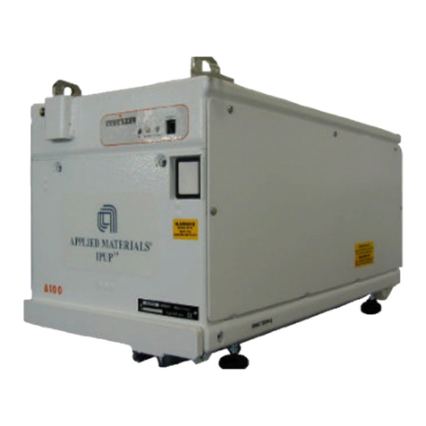
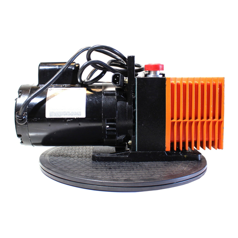
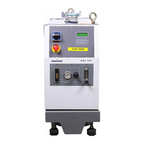
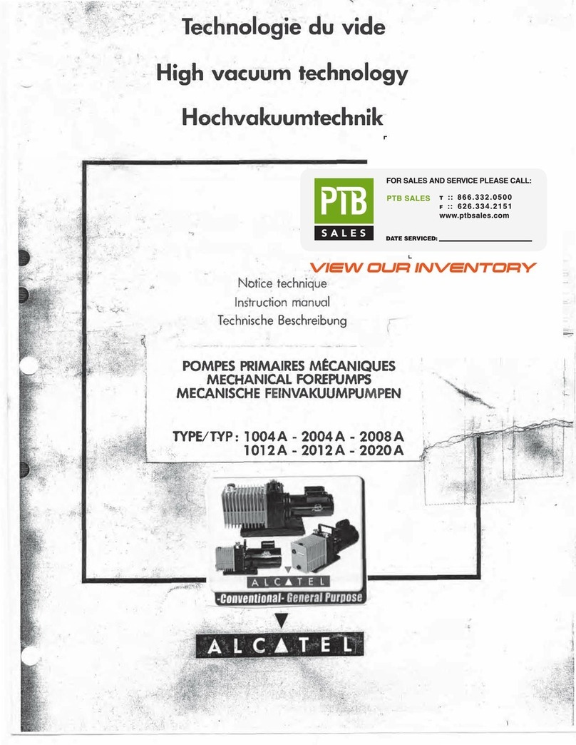
Alcatel 2008 A Operator's manual

ALCATEL 2008A Users Instruction Manual
■
POMPE PRIMAIRE MECANIQUE
■
MECHANICAL VACUUM PUMP
■
MECHANISCHE
FEINVAKUUMPUMPEN

N°de page Seite
I.
CARACTERISTIOUES TECHNIOUES
3
I.
TECHNISCHE OATEN
3
I.
TECHNICAL CHARACTERISTICS
3
11. UTILISATION 4 11. BENUTZUNG 4 11. OPERATION 4
2.1.
D escript ion
2.1.
B eschreibung
2.1.
D escript ion
2.2.
Premiere mise en route 2.2. Erst e Inbetriebnahme 2.2. Fir st starting
2.3.
M
i
s
e
en
route
en
service
normal
2..3
Norma
le
I
nb
etr
iebnahm
e
2.3.
Normal
starting
2.4.
Embou t d'aspiration
2.4.
Ansaugflansch
2.4.
Inlet connections
2.5.
Rob inet d
e
lestage
d'
air
2.5.
G
asbalI
a
st
ventiI
2.5.
Ga
s
ballast
valve
2.6.
Embout de refoulement
2.6.
Auspufflansch
2.6.
Outlet
111.
MAINTENANCE 7
111.
WARTUNG 7
111.
MAINTENANCE 7
3.1.
Vidange d'huile 3.1. Olwechsel 3.1. Dr ain ing of the oil
3.2.
Rin
c;
age
3..2
Olspulung
3.2.
Flu
shing
3.3.
D
emon
tage
3.3.
Demontage
3..3
Disman tling
3.4.
Remon tage 3.4. Montage 3.4. Re-assembly
3.5.
Commande des pieces de rechange 3.5. Ersatzteilbeschaffung 3.5. Ordering spare parts
3.6.
Ou t ill age 3.6. Werkzeug 3.6. Tools
IV. PLANCHESHORSTEXTE IV. ANLAGEN IV. ILLUSTRATIONS

I.
CARACTERISTIOUES TECHNIQUES
I.
TECHNISCHE OATEN
I.
TECHNICAL CHARACTER ISTICS
Lespompes primaires ALCATEL 2008 A sont e-
Die Vorvakuumpumpen ALCATEL 2008 A sind
A L CA TE L 2008 A vacuum pumps are equipped
qu ipees dun moteur triphase 220'300 Volts 50 Hz
mit Motoren fur 220/380 V 50 Hz Drehstrom
with 3-phase motors 220V/380 V, 50 Hz, or
ou d'un moteur monophase 220 Volts 50 Hz.
oder 220 V 50 Hz Wechselstrom bestuckt . D ie
single-phase motors 220 V, 50 Hz.
Lespompes primaires ALCATEL Z 2008 A sont
equipees d'un moteur triphase 220/ 240 Volts
Pumpentypen
Z
2008 sind mit Motoren fur
3 x 220 / 400 V 60 Hz oder 1 x 110 /2 20 V 60 H z
ALCATEL
Z
2008 A vacuum pumps are
60 Hz ou d'un moteur monophase 110 /2 20 Volts
60 Hz.
ausgerustet.
equipped with 3-phase m ot or s 220 /440 V, 60 Hz ,
or single-phase motors 110/ 220 V, 60 Hz.
50 Hz 60 Hz
Pompe
a
palette
a
2 etages
Drehschieberpumpe zweistufig
Vaned pump two stages
Vi.t esse de rotation ·synchrone
Nenn-drehzahl
Nominal rotational speed
1500 t.mn·
1
1800 t.mn·1
Debit nominal
Nennsaugvermogen
Free air displacement
10 m3 h·1
12
m3
h·l
Debit methode Pneurop
(1) Pression
Ii
mite (sans injection d'air)
Saugvermogen Nach Pneurop
(1) Enddruck (ohne Gasbal
last)
Air displacement Pneurop method
(1) Base prnssure (w ithou t gaz ballast)
7,5 m3 h-1 9 m3 h·1
<
1.,o -4 mbar
Quantite d'huile
Olfullung
Oil capacity
1
I.
Puissance moteur
Motorleistung
Power rate
0,37 kW
Poids triphase
Gewicht Drehstrom
Weight Three-phase
20,5 kg
Poids monophase
Gewicht Wechselstrom
Weight Single-phase
25 kg
Embout d'aspiration
Ansaugflansch
Inlet pneurop flange
NW 25
Embout de refoulement
Auspufflansch
Outlet pneurop flange
NW 25
(1) Mesuree par la methode Pneurop
(1) Nach Pneurop mit Mac Leod gemessen
( 1) Measured by Pneurop method.

II. UTILISATION 11. BENUTZUNG II.
OPERATION
2.1.
Descript io n
La planche 01 represente une coupe schema-
tique et une vue de cote de groupe de pompage.
A.
Bloc fonct ion nel : pompe mecanique a 2
palettes, a 2 et ages.
B.
Transmission : manchon d' accouplem ent .
C.
Moteur d'entr ainement . ,
D.
Levier de commande de l'interrupteur du
moteur.
E.
Aspiration
F.
Bouchon de rempl issage d 'h u ile.
G.
Niveau d'huile.
H.
Bouchon de vidange d' hu ile
I.
Robinet de lestage d' air
K. Refo ulem ent
2.2.
Pre m ie re mi se en route
Enlever les capsules de protec tion de !' as-
piration et du r efou lement
Brancher le moteur apres avoir veri fie la
tension d' alimen tat ion .
Version triphasee
Suivant la tension en triphase de 220 V ou
380 V, les connexions a l ' in t er i eur de la boi te
a bornes devront etre realisees sui vant le
schema inscrit a l ' interi eur du couvercle.
Donner une breve impulsion de courant et
verifier le sens de rotation du moteur.
L'extremite de l'arbr e doit tourner dans le
sensde la flecheplacee surle flasque poignee.
Version monophasee
Les pompes sont br ancheesen 220 V (50 Hz)
ou en 110/ 220 V (60 Hz) p ar l ' in termediaire
d' un cable de longueur 2 m. La fiche est
equipee d'une broche Terr e qu' il est ob ligat oi-
re de raccorder.
Le sens de rotation du moteur est fixe
a
l ' u sine.
2.1. .
Beschreibung
Anhang. 01 zeigt einen Schnitt und die
Seitenansicht der Pumpe
A.
Pumpenkorp er : zweistufige Pumpe mit 2
Schiebern
B.
Antrieb : elastische Kupp lung
C. Antriebsmotor
D. Motorschalter
E.
Ansaug
F.
Oleinfulloffnung
G.
Olstandsauge
H Olab la{fo f f nung
J.
Gasballf)st ventil
K. Auspuff
2.2. Erste I nbetriebnahme
Schutzkappen von dem Ansaugstutzen und
Auspuf f stut zen entf ernen
Motor an die vorgeschriebene Netzspann-
ung anschlie{3en.
Drehstromausfuhrung
Je nach der Netzspannung von 220 V
oder 380 V wird das Netzkabel in der
Klemmendo se entsprechend dem einlieg-
enden A nschlu/3pl an angeklemm t. Die
Drehrichtung wird durch kurzzeitiges
Ansch alten des Motors gepru f t . Sie wird
durch den Pfeil auf dem Flansch ange-
zeigt.
Wechselstromausf uhrung
Die Wech selst rom mo tore n sind mit Netz·
kabel von 2 m Lange versehen. Es ist d arauf
zu achten, da/3 die Massenleitung ange-
klemmt wird.
Der Motor kann. mit 110 V betrieben
werden, wenn die Kabel entsprechend
dem einliegenden Plan angeklem mt wer•
den. Es wird empfo hlen, einen Uber-
lastungsschutz zu verwenden.
2.1. .
Descriptio n
F igure 01 shows a diagramm ati cal cross·
section and a sid e-view of the pump unit.
A.
Pumping section : mechanical, 2-vane ,2-
stage pump
B.
Transm ission : coupling
C. Drive motor
D.
Motor sw itch
E.
Inlet
F.
Oil f il ter plug
G.
Oil level sight glass
H.
Oil drain plug
I.
Gas ballastvalve
K. Outlet
2.2.
First start ing
Remove the protective caps from the
inlet and outlet pipes.
Connect the motor, after checking the
supply vo!tage.
Three -phase mod e ls
Connect the terminals in the terminal box as
shown in the diagram reproduced inside the
lid , for 220 V or 380 V (50 Hz). 220 V or
440 V (60 Hz), as re qu ired .
Momentarily apply power and check the
direct ion of rot ation of the m ot or. Th e
end of the shaft must turn in thedirecti on
of the arrow on the fr ame. •
S ingle-phase models
The pump is delivered with a 2 meter l ong
cord (2 wires plus ground). Wiring is for
220 V ope r ation (50 Hz) or 110 / 22 0 op era•
t ion (60 Hz).
The rotat ion direction is set at the factory

II est recommande de proteger le moteur
pour son intensite nominale.
Devisser le bouchon de remplissage d'huile
et remplir la pompe jusqu'au milieu du
niveau. Cette operation doit etre faite
pompe arretee.
11 est normal que ce niveau varie Iorsque
la pompe tourne.
Utiliser indifferemment :
Huile ALCATE L VP 1
Huile SHELL TALPA
30
Huile ANTAR PV
600
Huile CODITEC PV 195 A
Raccorder la pompe
a
!'installation et la
faire tourner
On peut l'arr eter sans avoir
a
faire une
entree d' air , ia pompe etant etanche et
anti-retou r d' hu ile.
Oleinfullschraube abne hm en und
01
bis
zur Mitte des Olschauglases einfullen.
Dies mu{3 bei stehender Pumpe gemacht
werden. Nach Einschalten der Pumpe
sinkt der Olstand am Schauglas.
Es konnen wahlweise folgende Ole ver-
wendet werden :
ALCATEL VP 1
SHELL TALPA 945
ANTAR PV
600
CODITEC PV 195 A
Pumpe an die Vakuumleit u ng anschl ie{3en
und start en.
Die Pumpe braucht nach dem Abschalten
nicht betUftet
2u
vveiden.
Sie ist vakuum-
dicht und la/3t ke)n 01 hochsteigen.
Motor protection for the rated current
should preferably be provided.
Unscrew the oil filler plug and
fill to the
middle of the sigh t gl ass. This operation
should be carried out with the pump off.
It is quite normal for the level to vary when
the pump is rotating.
Oil level is always checked with pump at rest!
Any of·the following oils may be used :
ALCATEL VP1 oil
SHELL TALPA
30
oil
ANTAR PV
600
oil
CODITEC PV 195 A oil
-
I nstall the pump in the system and switch
it on.
-
The pump can be stopped without intro-
ducingair, as it is airtight and oi! migration
is impossible
2.3. M i se en route en service norm al
2.3.
Normale lnbetriebnahme
2..3
Normal starting
La pompe etant etanch e, aucune precaution
n' est a prendre meme p our les «demarrage s a fr oid »,
au -dessus toutefois d'une temperature minimale de
10" C.
Da die Pumpe dicht ist, kann sie auch ohne
Schwierigkeit kal t gestartet werden, wenn die Tempe-
ratur uber 1
o•
C li egt.
Since the pump is airtight, no precautions
need be taken on «cold starts)>, provided that the
temperature is not below 1
o•
C (40° F)
2.4. Embouts d'aspir at ion
2.4.
Ansaugfl ansch
2.4.
Inlet connection
L ' or if ic e d'aspiration de la pompe est equipe
d'un embout Pneurop NW 25 pour raccord rapide
(52594), permettant le raccordement de nom breu x
accessoires, Se reporter aux notices : 1:lements de
canali sat ion, Vannes
a
vide, ...
Die Ansaugoffnung der Pumpe ist mit einem
Pneuro p-anschluss NW 25 versehen fur Schnellver-
bierdung (52594) mit verschiedenem Zubeh or .
Siehe Notizen von, Vent ilen, Kanalisationen,...
The pump inlet port is equipped with a
NW 25 flanged pipe (P/N 52594). Connection of
different nipples or fittings is secure d
by
qu ick
connect clamp. (see Alcatel catalogues : Vacuum
Fittings, High vacuum Valves).
_ 5 _

2.5.
Robinet de lestage d' air
2.5.
Gasballastventil 2.5. Gas ballast valve
Si la pompe doit aspire r .des vapeurs co nden-
sables, o u vrir le ro binet de lestage d' air en de vissant le
bouchon mo lete (repere
1).
Dans le c:as ou la pompe a absorbe une quanti-
te de vapeurs condensables importantes, ii est possible
que le co ndensat soit emu ls io nne dans l' hu ile de la
po mpe. Dans ce cas, ii suffit de fermer !'asp irat io n et
de faire fonctionner la pompe sur elle-meme avec son
robinet de lestage d' air completement ouvert pendant
environ
30
minu tes, pour regenerer l' hu ile.
2.6.
Embout de refo ulement
L' orifice de refoulement de la pompe est equi-
pe d' un embout Pneurop NW
25
pour racco rd rapide
(52595),
permettant le racco rdeme nt de divers acces-
soires et notamment d'un separateur de brouilla rd
d' hu ile
52599.
Wenn die Pumpe kondensierba re Dampfe
abpumpen soll, mu{3 das Gasba llastve nt il (ge randelte r
Dreh knopf ) geo ffnet werden.
Hat die Pumpe bereits eine gewisse Menge
kondensierbare Dampfe abgesaugt, dann bildet das
Ko ndensat moglic herwe ise mit dem 01 e ine Emulsio n.
In dem Fal l sc h l ie{3t man den Ansaugstu.tzen, offnet
das Gasballastventil und la{3t die Pumpe ca. 30 min
gegen vollen Gasba llast laufen, um das
01
zu
regenerie ren.
2.6. Auspuff lansch
Die Auspuffoffnung der Pum pe ist mit einem
Pneurop-anschluss NW
25
versehen fur Schnellver-
bierdung
(52595)
mit verschiedenem Zubehor und
lediglich mit einem Olabscheider
52599.
When pumping condensable vapours, open
the gas ballast ·valve by unscrewing the knurled
knob (I in f ig. 01 ).
If the pump has absorbed a considerable
amount of co ndensable vapo urs, the co ndensate may
become emu lsi f ied w it h the pump oil. I n this case, it
is merely necessary to close the inlet nd run the
pump by itself with the gas balla st valve fully open
for approx.
30
min., to rege nerate the oil.
2.6.
Exhaust of pumped gases
The exhaust port of the pump is equipped
with a
NW
25
flanged pipe ( P/ N
52595).
To pump out the oil mist delivered when the
pump is working at high pressure a hose nip p le can be
co nnec ted to th is flanged pipe (see 2.4.)
An oil mist eliminator (P/ N
52599)
can also
be fitted on the outlet.

111.
MAINTENANCE
111.
WARTUNG
111.
MAINTENANCE
3.1.
Vidange d'huil e
3.1.
Olwechsel 3.1. Draining the oil
La vidange doir erre faite lorsque la pompe
est ch aude.
Devisser le bouchon de vidange (pl.
01
repere H).
Lor sque toute l'huile de la cuve s' est ecoulee,
revisser provisoirement le bouchon H et faire tourner
la pompe pendant 10 secondes environ en laissant
l' aspir ation ouvert e pour chasser l 'hu i le du bl oc
fonctionnel.
Elim iner cette huile par le bouchon
H.
Visser le bouchon
H
Devisser le bouchon de remplissage d'huile
(pl. 01 repere F)
Rernplir avec de l' hu ile neuve jusqu'au
milieu du niveau (pl. 01, repere G).
3.2.
Rin age
L'o per ation de vidange peut s' accom pagner
d'une operation de rin<;age, si l'on constate que
l'huile de vidange est sale. Pour le rin<;age, ii faut
compter une quantite d'huile neuve egale
a l
a capacite
de la pompe en huile.
Apres avoir vidange l' hui le de la cuve, revisser
provisoirement le bouchon repere
H .
Faire tourner la
pompe. en faisant couler l'huile neuve dans !'orifice
d'aspir ation .
Arr eter la pom pe et elim iner l'huile de rinc;a-
ge par le bouchon
H.
Visser le bouchon
H
et faire le
plein d'huile neuve.
Der Olwechsel darf nur be, warmer Pumpe
vorgenommen werden.
Olablap schr aube (Teil , Anhang
01)
herausdrehen. Wenn alles 01 abgelassen ist,
Schraube wieder einlegen und die Pumpe
etwa
10
sec m i t o ff enem _A saugstu t zen
laufen lassen, damit das 01 aus dem
Schopfraum der Pumpe herausgetrieben
wird . Auch dieses
01
wird durch die
Ablaf3o t f nu ng
H
en tfern t.
Olabla/3 mit der Schraube H verschl ie) en .
Verschlu p der O lein la/3o ff nu ng abschrau-
ben (T eil F Anhang 01)
Fr isches
01
bis zur Mitte des Schauglases
(TeiI G Anhang 01) ein fu llen.
3.2. Olspulung
1st das
01
in der Pumpe stark verschmutzt•
dann sollte der Olwechsel mit einer Spulung verbunden
werden.
Dazu benotigt man eine Olmenge, die grop er
ist als die normale Fullmenge. Nach dem Ol ablaµ
wird die Offnung provisori sch mit Teil
H
versch l ossen.
Dann
gieP
t man das frische
01
in die A n saugof fnu ng
der laufenden Pumpe. Dann wird die Pumpe
abgeschaltet
und
das
01
abgelassen
.
Nach
V
er
schr
au-
ben des Verschlusses
H
wird frisches
01
eingefullt.
The
quality
of
the
pump
oil
is
extremely
im
por
a
t
nt
for
proper
operation
The
vacuum
pump
oil
mu
st
be
in
_
sp
ected
periodically
for
_
con
tam
inan!
s
and
oil level which must be maintained m the centerof the sight glass.
011
level
is checked with the pump not rotating because he lev I will ary du ing
opera
tion
.
Alcatel
pump
s
may
be
turned
off
for
visual
ml
level
inspection,
whilebackingdiffusionpumps.etc..asthey sealunder vacuum whenturned
off.
The
oil
consumtpion
.
due
to
exhausting
gases
,
will
depend
upon
fr
e-
quency of pump down and operating pressure.
Al
cat
el
Exhaust
Mist
Eliminators
will
reduce
loss
co
nside
rably
by
conde
nsin
g
expelled oil vapors, and returning the oil to the reservoir.
I
nspec
i
o
t
n
o
f
th
e
oil
leve
l
will
also
indicate
oil
co
nt
amination
.
The
oil
should
have a light amber color.
If
brownishin color,the oil should be change.d
Another indication of oil contamination, is an increase in base pressure of
thepump. Alcatel pumps are equipped with gasballast. which canbeused
t
o
re
ge
nerate
ml
co
ntam
in
ated
with
condens
b
a
l
e
vapors
.
The
oil
will
be
cloudywith a high basepressure.In thiscase.closetheinlet andopen
thegas ballast valveIor approximately thirty (30) minute.sThe basepressure
should
reduce
to
a
norma
l
value
after
clo
sin
g
the
gas
ba
lla
st
valve.
3.2.
Flushing
If the base pressure is still high, an oil changemust be performed
The oil should be drained when hot and discarded. When the oil has
drained, vent theintake and run the pump for several seconds to expel oil
trapped inside the pump stages.Re-chargewith fresh clean oil through
the fill plug. to the middle of thesight glass.
In some extreme cases, deposits have built up inside the pump so that
new oil is contaminated within a few hours In this case, the flushing
procedure should be performed, as detailed herein.
Drain oil from hot pump and re-install the drain plug. Place a cloth lightly
over the exhaust port to contain oil splash. Turn the pump on, with inlet
open
and
slo
wly
pour
fr
esh
oil
into
the
inl
et
-
equal
to
the
pump
's
c
a
p
acity.
Turn off pump and drain flushing oil. Re-chargeoil level to middle of
sight glass by way of the oil fill plug.Alcatedoil VPl is recommended
lor re-chargingor flushing Alcatel vacuum pumps
The cleanliness of the oil will greatly prolong the life and performance
ol the pump. A blank statement for oil changescannot be made for all
a
pplication
,
s
due
to
the
dif
f
erences
in
operating
co
ndition
s.
A
genera
l
rule
is
th
e
oil
change
every
2
to
3
months
in
clean
a
pplications
;
ie, diffusion fore pump on UHV systems
Extreme
a
pplic
ation
s.
s
uch
as
ion
implan
ta
tion,
chemical
stripp
n
i
g
or
et
ching
systems
could
r
e
quire
weekly
ma
i
ntenanc
o
e
il
changes
or
expensive
trappingtechniques.

3.3.
De m o nt a
ge
3.3.
De
montage
3.3.
Dismantling
L' en t ret ie n de nos pompes ne necessite en
utilisation normale que le remplacement de l'huile
fonctio nnelle ou un rin<;a ge.
Cependant, !'a bsorp tio n p ro lo ngee de gaz
charges de poussiere ou de vapeurs acides peut provo-
quer un encrassement tel que le rinc;age de la pompe
avec l' h uile soit insuff isant.
Dans ce cas, ii est necessaire de proceder au
demont age de la pompe et au lavage de toutes les
pieces au tric hlo re t hy le ne, ou perchlo rethy le ne.
Les pompes ALCATEL sont conc;ues de telle
sorte que le ur de montage est aise et que leur remonta·
ge ne necessite aucun regla ge . En effet, tous
les e le
-
ments qui doivent conserver des positions relatives
co nstantes sont pie te s apres un reglage precis en usine
et, lors du remontage, les differentes pieces sont inva -
riablement «en place)) par le sim p le senage des ecrous
et des
vis .
Enfin
i'o
utillage necessa1rese reduit
a
quelques
clesqui font generalement partie de l'outillage courant
d'un service d'entretien.
Avant de demonter la pompe, effectuer la
vi
dance
d'h
u
i
l
e
(voir
paragraphe
3.1.
).
La premiere phase de demontage (planche 02)
consiste
a
sortir le bloc fonctionnel de sa cuve.
La deuxieme phase concerne le demontage
du bloc fonctionnel (planche 03).
Die Wartung unserer Pumpe n, bei normalen
Betrieb, beschtrankt sich auf eine regelmassige Reini-
gung der Filte r und
Olwec
hse l.
Trotzdem kann la ngzeit ig es Abpumpen von
staubhaltigen Gasen oder Sauredampfen zu einer
Verschmutzung fuhren, die mit einem Olwechsel
nicht zu beheben ist.
Es mu dann die Pumpe zelegt und alle
E inze lt e i le in Trichlorathylen oder Perchlorathylen
gereinigt werden. Die Pumpen von ALCATE L sind
so ko nst ru
ie
rt,
da /3 die
De mo ntage au /Je rst unkompli·
ziert ist und die Montage keine Justierungen erfordert.
Alie gepa{3t
e
n Teile sind nach der Justierung im Werk
verstiftet und sind nach Anziehen der Schrauben
justiert. Fo lgl ic h wird zur Wartung auch nur das in
jed e r mechanischen Werkstatt vorhandene Werkzeug
benotigt.
Vor Demontage der Pumpe
01
ablassen
(Kap.
3.1).
Als erstes wird der Pumpen ko rpe r aus
dem Gehause genommen. Als zweites wird der
Pumpe nko rper zelegt (Anhang 03 ).
The only regular maintenance requ ired by
our pumps is changing the oil or f lush ing.
Ho weve r, p ro lo nged absorption of dust or acid-
vapor-laden gases may produce clogging which can no
lo nger be removed by flushing out with oil.
In that event the pump must be dismantled
and all parts, except gaskets and seals, washed in
trichloroethylene, or perchlo roethy le ne.
ALCATEL pumps are designed for easy
dismantling, and no adjustments are required on re-
assembly. All parts whose relative positions must remain
constant are doweled after accurate setting at the
factory, and on re-assem bly the various parts will
always be located in their correct positions by merely
tightening the screws and nuts.
The only tools required are a few wrenches,
which will generally form part of the standard equ ip ·
ment of any maint enance department.
Before dismantling the pump, drain the oil
(see section
3.1.).
The first step of dismantling (fig. 02) is to
remove the pumping section from its chamber.
The second step is to dismantle the pumping
section (f ig. 03 ).

3.3.1
. Demont age du groupe moto-pompe
(planche 02)
3.3.1. Demontage der Pumpe
(Anhang 02)
3.3.1.
Dismantling of the pumping section
(f ig. 02)
Devisser les quatr e ecrous 71 .211 ainsi que
la vis
75.530
de fixation du flasque sur le
bati .
Tirer !'ensemble flasque poignee
52.547
et
mo teur.
Prendr e soin de ne pas deterior er le joint
deflecteur
52.555.
Les deux rnoities de l'accouplement venti-
lateur demeurent, l'une cote moteur, l' au -
tre cote pompe.
Les pompes equ ipees d'un moteur a1:
standard americain, comportent entre le
flasque poignee
52.547
et le moteur, un
fl asque d'adaptation
52.589.
- Retirer la cuve en prenant soin de ne pas
cleteric rer !e joi nt p!at 52.548.
Demont er la vis 82.734 et l'etrier support
52.566.
Retirer l'embou t d'aspiration
52.594,
le
filtre
52.565,
l'embou t de refoulement
52.595.
Vier Muttern 71211 und die Schraube
75530
der Befestigung des Flansches am
Fu/3 abschrauben .
Tr agf l ansch
52547
und Motor abz iehen.
Dabei darf die Dichtung
52555
nicht
beschadigt werden. Die beiden Achsen der
Ventilatorkupplung bleiben, die eine an
der Mo tor seit e, die andere an der Pumpen-
seite. Die Pumpen, die m it einem ameri -
k an ischen Motor ausgerustet sind, haben
zw ischen dem Tragflansch
52547
und dem
Motor einen Adapterflansch
52589.
Gehause abziehen. Dabeidartdie Dichtung
52548 nicht beschadigt werden.
Mutter
82734
und Haltebugel
52566
abnehm en.
Ansaugstutzen
52594,
Filter
52565
und
Auspuffstutzen
52595
abnehmen.
Unscrew the four handle plate fixing nuts
71211
and the fixing screw
75530 .
Pul l out the hand le plate
5254 7
toge th er
with the motor . Be careful not to damage
the flat gasket
52555 .
One half of the
coupling assembly remains on the pump
side ( fan ), the other one comes ou t on the
motor shaft.
The pumps equipped with an Am erican
made motor get an adaptor flange
52589
mounted between the handle plate and the
motor.
Remove the oil casing being careful not to
damage the flat gasket
52548
Unscrew the inlet -ou t let fl ange f i xi ng
screw 82734 and remove the f lange 52566
Remove the inlet port
52594,
the filter
52565
and the out let por t
52595.
-
-
-9 -

3.3.2.
Demontage du bloc fonctionnel
(planches
02
et
03)
3.3 .2. Demontage des Pumpenkorper s
(Anhang
02, 03)
3.3.2.
Dism antling of the pumping section
(fig.
02
+
03)
Avant demontage, on fera attention aux po si-
tions des stators et des flasques. Ceux-c
i
sont posi-
tionnes avec une grande precision lors du montage en
usine.
11
faudra respecter ces memes positions au re-
montage pour eviter de deteriorer les logements des
pieds de posit
io
n.
Demonter le pare-ec
lats
52.538
en de
vis
-
sant les vis
75.508.
Retirer les ressorts de soupapes
52.541
et les soupapes
52.540.
Demonter le pied support
52.521
en
devissant les vis
75.514.
Faire tourner le ventilateur pour devisse r
par
le bas de la
pompe,
la
vis
de
b
l
oc
a
ge
de
clavette
75.554.
Retirer l'accouplement ventilateur
52.552
et la clavette
83.649.
Disposer ensuite la pompe
,a
axe
vertical.
Enlever le moulinet porte-came
83.290
en
retirant le circlips
71.161
en
la iss
ant en
place le support d'axe
52.567
du levier
po rte -c
lape t
52.578.
Vor der Demontage achte man auf dieStellung
des Stators und der Flansche. Diese sollte bei der
Montage wieder eingenommen werden, um eine
Beschadigung der Stiftlocher zu ve rme id e n.
Schrauben
75508
losen und Splitterschutz
52538 abm o nt
fe
ren.
Ventilfedern
52541
und Ve nt il klappe
52540
entfernen
Schrauben
75514
abschrauben und Pum-
penfu/3
52521
abnehmen.
Ventilator so drehen, da/3 die Sicherungs-
schraube fur den Keil
75554
abgeschraubt
werden kann.
Ventiiatorscheibe
52552
und Keil
83649
abnehmen.
Pumpe senkrecht stel len. Seegerring
71161
herausnehmen und das Flugelrad mit der
Nockenwelle
83290
abz ie he n. Die Ha lt e -
rung
52567
fur die Ventilklappenfeder
52578
bleibt an Ort und Stelle.
Before
dism a
ntli ng, carefully note the posi-
tions of the bearing plates and the stators. These,a e
precision-located on the bearing plates on assembly at
the factory, and must be replaced in the same posit io ns
on re-assembly in order not to damage the dowel
pin holes. Note part numbers.
Remove the cover
52.538,
by unscrewing
the two fixing screws
75508.
Remove the
valve
sp ring s
52541
and the
valves
52540
Remove the pump base
52521
by ins-
crewing the two set screws
75514
Put the pump upside down then turn
the fan by hand and unscrew the shaft key
set screw
75554
Remove the fan coupling
52552
and the
key
83649.
Place the pump vertically. Remove the
impeller
83290
which is fixed on the shaft
by means of circl ip
71161.
There is no
need to remove the
valve
lever assembly
72578
from its bracket
52567.
_ 10 _

a)
Depose du f/asque arriere 52.571
Devisser les
3
ecrous
71.214.
I ntrodu ire dans les deux redans deux tour-
nevis. Les faire tourner sur eux-memes par
rapport
a
leur axe pour degager le flasque
de ses pieds. Tirer le flasque dans l'axe en
prenant bien soin de ne pas deteriorer les
levres du joint d'etancheite
83.645.
Re t ire r
le joint torique
79.030.
Le systeme d'etancheite a ete regle en usi-
ne, son demontage necessite un nouveau
reglage qui sera precise au chapitre remon-
t age. On peut cependant demonter le
flasque arriere sans avoir
a
modifier le
reglage du systeme antibruit.
b)
Depose du rotor 52.510
Sortir le rotor
52.510
en le faisant gl isser
le long du double alesage.
a)
Demontage des hin teren F/ansches52571
Drei Muttern
71214
abschrauben
Der Flansch wird mit Hilfe von zwei in
den seitlichen Nuten eingesetzten Schraub-
endrehern gel6st. Das Abziehen uber die
Achse mu/3 vorsichtig und unter leichter
Drehung erfolgen, damit der Simmerring
83645 nicht beschadigt wird. Dichtung
79030 abnehmen. Das Dic htu ngssystem
wurde im Werk justiert. Die Demontage
macht eine im Kapitel
«
Mo ntage » be-
schriebene Neujustierung no tig. Das Ge-
rauschdampfungssystem braucht alle rd ings
nicht zelegt zu werden.
b)
Demontage des Rotors HP 52570
Rotor
52510
uber die Doppelbohrung
gleitend herausziehen.
a)
Removal of the rear bearing plate 52571
Unscrew the three nuts
71214
Unsert two screwdrivers into the slots at
180°
to each othe r. Turn them about
their axis to release the bearing plate from
its doweling
pin s.
Pull out the plate along its axis, being
careful not to damage the shaft seal lips
83645.
Remove the o-ring
79030
The a:iti-suckback system is set at the
factory. If dismantled, it must be reset as
described under «re-assembly>>. Ho wever,
the rear bearing pla te can be removed
without dist urbing the setting of the seal ing
system.
b)
Removal of the high pressure rotor 52510
Make it slide along the double bore of the
stato r.
Sortir !es palettes
83.946
et !eurs
ressorts
Schieber
83946
und
Federn
53040
her-
Remove the vanes
83946
and the springs
53.040.
ausnehmen.
53040.
c)
Depose du stator 52.'572
- lntro du
ire
dans les deux redans, deuxtour-
nevis et proceder comme au paragraphe a.
Retirer le joint torique
79.030
d)
Depose du flasque median 52.573
I
ntrodu ire dans les deux red ans, deux tour-
nevis et proceder comme au paragraphe a.
Re ti rer le joint torique
79.030.
e)
Depose du rotor 52.512
Sortir le rotor
52.512
en evitant de le faire
tourner, ceci afin d'eviter de deteriorer le
joint a levres 83.645.
Sortir le s palettes
53.106
et le urs ressorts
53.040.
c)
Demontage des Stators 52572
Stator mit 2 Schraubendrehern losen wie
in Pt. a) beschrieben und abziehen.
Dicht u ng
79030
abnehme n.
d)
Demontage des mittleren F/ansches 52573
Flansch mit Hilfe van 2 Schraubendrehern
losen wie im Pt. a) beschrieben
Dichtungsring
79030
entfernen.
e)
Demontage des Rotors BP 52512
Rotor
52512
ohne Dreh ung herausz iehe n,
damit die Lippen des Simmerringes
83645
nicht beschadigt werden.
- Schieber
53106
mit Federn
53040
herausnehmen.
c)
Removal of the high pressure stator 52572
Use two screwdrivers as ind ic a ted here-
above (a)
Remove the o-ring
79030.
d)
Removal of the central bearing plate 52573
Use two screwdrivers as indicated here-
above (a)
Remove the o-ring
79030
e)
Removal of the low pressure rotor 52512
Re move the rotor
52512
by sl id ing along
the double bore of the stator, being careful
not to turn it in order to prevent damaging
the lips of the shaft seal
83645.
Remove the vanes
53106
and their springs
53040.
)

f)
Depose du stator 52.582
I
ntrodu iredans lesdeux redans, deux tour-
nevis et proceder comme au paragraphe a.
Re t irer le joint torique
79.030.
g)
Depose du flasque avant 52.575
I
ntrodu ire dans lesdeux redans, deux tour-
nevis et proceder comme au paragraphe a.
Retirer le ressort
52.564
et la bille
82.522
du lest d'air.
Retirer les joints toriques
79.030
et
83.633
h)
Demontage du lest d'air
Devisse r la vis
52.560.
Retirer le bouton
52.559,
le piston
52.5"61,
le ressort
52.563
et le clapet
52.562.
i)
Circulation d'huile
f)
Demontage des Stators 52582
Stator mit H ilfe von 2 Schraubendrehern
losen wie in Pt. a) beschreiben.
Dichtungsring
79030
abnehmen.
g)
Demontage des vorderen Flansches 52575
Flansch mit Hilfe von
2
Schraubendrehern
losen wie in Pt. a) beschrieben.
Feder
52564
und Kugel des Gasba ll ast-
ventils
82522
entfernen.
Dichtungen
79030
und
83633
entfernen
h)
Demontage des Gasballastventils
Schraube
52560
abschrauben
Knopf
52559,
Stempel
52561,
Feder
52563
und Klappe
52562
abnehmen.
i)
01/eitung
f)
Removal of the low pressure stator 52582
Use two screwdrivers as indicated here-
above (a)
Remove the o-ring
79030
g)
Removal of the front bearing plate52575
Use two screwdrivers as described here-
above (a)
Remove the spring
52564
and the gas
ballast ball
82522
Re move the o -rings 79030 and 83633.
h)
Removal of the gas ballast
Unscrew the screw
52560
Remove the knob
52559,
the pisto11
52561,
the spring
52563
and the seal
52562.
i)
Oil circulation
I -I. . L.....
:.£:--+:....
_ - 1
....
..&..........+ . . ..... -
.......
11 &,.., , ; 1 ,.,.
rl,,
h,..... ;_
n ta
C!,-.hm;or11nn rlar D1uv,no Or'fn.ln+-
"311r
.oino.rn
TJ....,.. -• ,_..,.....,.,.. ........... ,l . _l,... ; ,.. ,...,. "' ...J h.,
.,_,..,..._.,.
_,,:; .-.- -:1
L d
IUUI
IIH;dllUII :,
t'l
lt'l,LUt'
!-'di
I
IIUllt' UUUOIII
prelevee sous le clapet d'etancheite monte sur le levier
52.578.
Le debit d'huile est controle par le gicleur
83.954
visse sur le support
83.410
du systeme d'etan-
c heite.
Sur les pompes doubles, le premier etage est
graisse par circulation au travers du flasque interme-
diaire.
Le debit est t im it e
par le
gicleur
53.474.
II
n 'est pas recommande de demonter ce gi-
cleur pour son nettoyage.
11
suffit de verifier qu'il n'est
pas bouche en envoyant au travers un jet d'air com-
prime.
LJIC.
V lllllf'GI
UII
OC.:I I
UlflfJc;
c;1IVl
l
au.>
c;111c;111
Olbad, das unter der Ventilklappe auf dem Hebel
52578
angesaugtwird.DieDurchflu/3m e nge wird durch
eine auf dem Support
83410
aufgeschraubte Duse
83954
begrenzt.
Be-i den
zweistufigen Pumpen wird das
01
fur
die Schmierung durch den Mittelflansch geleitet. Die
Durchflu/3menge wird durch die Duse
53474
be-
grenzt. Die Oldusen sollten bei der Reinigung der
Pumpe nicht ausgeschraubt werden. Es genugt eine
visuelle Kontrolle, da/3 sie nicht verstopft sind.
I
llt'
µu111µ:,
Olt' IUUI ll,dlt'U
uy
l l lt'dl l:, u, dll VII
bath, the oil being taken from below
the
ant i-suc kbac k
valve mounted on lever
52578.
The o
il
flow is controlled by the jet
83954
screwed to the sealing system support
83410.
On the two-
stage pumps, the first stage is lubr
ic
ated by oil passing
through a bore in the intermediate plate.
The oil flow is controlled by a jet
53474.
Dismantling this jet
for
cleaning is not
recommended ; it is merely necessary to check that it
is not blocked by blowing through with compressed
it .
_ 12 _

3.3.3.
Nett oyage des pi eces et rempl acement des
joint s
a)
netto yage
Le nettoyage de to utes les pieces metalI iques
sera fait dans du trichlorethylene,
a
l'aide d'un pinceau.
11
faudra proscrire absolument l'usage des chiffons.
Les joints ne seront pas mis au contact du
trichlorethylene qui risque de les deformer.
b)
Remplacement des joints
On verifiera que les joints sont en ban etat .
II est fo rte ment co nseille de changer systematiquement
tous les joints
a
chaque demontage, on evite ainsi la
re ut il isation de pieces douteuses.
11 est
prevu une
pochette de joints de rechange (voir plus
lo
in ).
3.4.
Remont age
Avant de proceder au mo ntage, toutes les
pieces netto yees au trichlo re thy
lene
seront sechees
a
l'air comprime.
Les operations de remontage seront executees
exactement dans l'ordre inverse des operations de
demo ntage .
11 faudra respecter les consignes suivantes :
Eviter de mettre trop d'huile au fond des
logements des pieds decentragedesflasques
et stator.
Enduire avec de l'huile de graissage de la
pompe, toutes les parties metalliques ainsi
que les levres des bagues d'e ta nche ite
83.645 .
11 est
important, lorgque le bloc
fonctionnel sera remo nte, de remplir d' hu i-
le les deux trous de graissage du flasque
avant
52.575.
Serrer sans forcer les trois ecrous
71.214
(co u ple max im al 1 m.kg.)
Refaire le reglage d u systeme d'eta nc heite
s'il a ete totalement demonte en procedan t
de la fa9on suivante (voir pla nche 04 ).
3.3.3. Reinigungder Einzelteile und
Michtungswechsel
a)
Reinigung
Die Reinigung aller Me ta lltei le sollte mit
Hilfe einer Pinzette in Tric hlo rat hyle n durchgefuhrt
werde n. Dabei sind Pinsel zu benutzen. Die Dichtungen
durfe n nicht mit Trichlo rathy len in Beruhrung
kommen, da sie dadurch deformie rt werden konnen.
b)
Einsetzen der Dichtungen
Vor dem Einset ze n mussen die Dichtungen auf
ordm ungsgemassen Zustand gepruft werden. Es wird
fest empfolen nach jeder Demontage d ie Dic h- tungen
auszuwechseln. Damit verhutet man die wiederbenutzung
van zweifc lhaf te n Dichtungen. Ein satz von Dichtungen
ist vorgeschen (siche weite r ).
3.4.
M o nt age
Vor der Mo ntage mussen alle in Tric hlo r a·
thy le n gereinigten Teile mit Hei.{3 luft getrocknet
werden.
Alie Mo ntagesc hritte sind in genau um·
gekehrter Reihenfolge vorzunehmen wie die De-
montage .
Dabei empfiehIt essich, folgendes zu beachtem :
In den Sitzen der Zentrierungen von
Flanschen und Stator sollte nicht zu viel
0
1
sein.
Alie Met al lte ile und der Simmerring 83645
sollte n vor der Montage leicht mit Pumpe·
nol bestrichen werden. Wesentlich ist, da.{3
nach der Montage des Pumpenkorpers die
beiden Olka nale des vorderen Flansches
52575
mit
01
gefullt werden.
Drei Muttern
71214
mit maximal
1
mkp
anziehen.
Wenn das Dic htu ngssystem zelegt war,
mu.{3 es nach folgendem Schema justiert
werden (Anhang 04).
3.3.3.
Cleaningof parts and replacement of gaske ts
a)
Cleaning
Al l metal parts must beclea ned with tric h lo-
roethylene, using a brush. Rags and cloths must on no
account be used .
Gaskets must not come into contact wit h
trichloroethylene.
b)
Replacement of gaskets
Check taht the gaskets are in good condition
and replace as required.
3.3.4.
Re-assembl y
Before re-assem bly , d ry all parts cle a n ed
with trichloroethylene by means of compressed air. Re-
assembly must be carried out in the exact reverse order of
the dism antl ing operat io n·s . noting however the
following points :
All the metallic parts and the Iips of the
shaft seals
83645
will be coated with
lubricating pump oil, being careful to not
f ill the doweling pin holes.
After the pump has been re-asse mbled , it
is important to fill up the two ho les of the
front bearing plate
52575
with oil.
Use a torque wrench to tighten the three
nuts
71214.
Maximum torque :
1
kgf-
meter .
The ant i-suc hbac k valve assembly must be
re-ad justed only if it has been complete ly
dismantled. Proceed as follows (see figure
04)..
_ 13_

a)
Faire tourner l'arbre de la pompe jusqu'a ce que
les
axes du moulinet (Al, du circlips (B) et du siege (C)
soient alignes
a
l'horizontale, (Bl etant entre (A) et
(Cl.
b)
Exercer ensuite une legere pression en (F) de tac;on
a
excentrer la came.
L'ec art e me nt entre le siege (C) et le clapet
(3)
doit etre alors de 1 mm.
11
se regle en
agissant sur la position du support
(
1)
.
L' axe (2) du trou d'entree d'huile et la
face du clapet (3) doivent etre sensible-
ment perpendiculaire. Le reglage se fait en
modifiant !'orientation du siege (C).
Apres ces reglages, ii est indispensable de
verifier que lorsqu'on relache la pression
(F), le clape t (3) revie n t bien s'appuyer
sur le siege (C).
al P umpe nwelle drehen bis die Axen des Flugelrades
(A) des seegerings (Bl und des Sitzes (Cl in
ho rizo n ta ler Lage aligniert sind (B Zwischen A und C).
b) Einen leichten Druck in Richtung ( F) ausuben um
den Nocken zu dezentrieren.
Der Abstand zwischen Sitz (C) und Vent il-
klappe
(3)
soil dan von
1
mm Sein.
Er stellt sich ein durch eine verschiebung
der Hal te ru ng der Ventilhebelachse (
1).
- Die Achse der Olbohrung (2) und die Klappe
mussen Zueinander Senkrecht stchen. Dies
wird erreicht durch Orientierung des
Klap
pe nsitzes .
Nach diesen Justierungen ist es unbedingt
not ig
zu
prufen das die Klappe (3) gut auf
dem Kla p p e nsitz (Cl anfliegt wenn der
Druck (F) ausgelost wird.
a) Slowly turn the pump shaft cqunterclockwise until
the axes of the impeller (A), clips (B) and the seat (Cl
are in line .
bl Offset the came while holding the impeller with a
finger so as to expert
a
sl ight force in (F) direction.
With the came offset, the an ti-suc kbac k
valve should be ab
le to
rise to about
1
mm
(.025").
The surface of the seat (C) and the an ti-
suckback valve (3l must be parrallel. This
adjustment is made by loosening the screw
(4)
and ro tat ing seat
(C).
After these operations. check that the
lever returns properly to its seat (C).
3.5.
Commande des pieces de rechange
3.5.
Ersatzteilbestellung
3.3.5.
Ordering sp are part
Dans le but d'obtenir satisfaction dans le
minimum de temps, ii est reco mmande , pour comman-
der des pieces de rec hange, de preciser :
1)
le type de la pompe
2)
son numero de serie
(ces indications sont portees sur !'etiquette
matricule fixee sur la console 52.545).
3)
le numero d'identification de la piece qui
figure sur les planches de la presente
not ice.
Afin de simplifier le s operations de mainte-
nance, nous avons prevu des pochettes pretes-a l' usage,
des pieces detachees les plus courantes. Ces ensembles
sont toujours disponibles en nos magasins . L' util isat io n
de ces pochettes est recommandee car vous aurez ainsi
la certitude de posseder toutes les pieces dont vous
pouvez avoir besoin. D' au tre part, vous serez servi plus
rapidement, sans risques d'erreur ou de confusion, car
!'explo it at io n de vos ordres sera simp l if ie e.
Um die Ersatzteill1eferung mit einem min,-
malen Zeit verlust durchzufuhren, sollte in der Be-
stellung.
1)
der Pumpentyp
2l die Seriennummer (die Angaben sind dem
Typenschild auf der Konsole 52545 zu
entnehmen)
3) die Ersatzte il nu mme r aus dem Plan ange-
geben sein.
Zur Vereinfachung der Wartungsarbeiten
bieten wir Repara tu rsat ze an. die alle zur Wartung
benotigten Ersatzteile enthalten. Wir empfehlen die
Verwendung solcher Sat2e, da dann mit Sicherheit
all e benotigten Austauschteile vorhanden sind.
Au erdem vereinfacht sich damit die Ersatzteilbe-
schaffung.
_ 14_
Fo r quick delivery of spare parts alw ays note :
1)
The typ of pump
2)
The serial number
These particulars are given on the spec if i-
c at io n label attached to bracket 52545.
3)
the part number as shown in the acc om-
panying illustrations.
To simplify maintenance, we provide re ady-
packed kits of most commo nly required parts. The se
kits are always availa b le . The use of these kits is
recommended. as you are then certain of having all
the parts that you are likely to need. In addit io n, you
will receive faster service without ris k of erro r or
confusion.

Pochette de joints 52.610
Cette pochet te comprend tous les joints de la
pompe et les pieces qu'il est necessaire de changer
a
chaque demontage complet.
Lot de maintenance 2 ans 52.613
Cette pochette comprend, en plus des ele-
ments de la pochette de joints 52.610, un ensemble de
pieces detachees permettant d'assurer la maintenance
de la pompe pendant une duree de 2 ans dans des
condit io ns d 'ex plo
itat io
n normales.
Nata
:
II peut etre fourni separement le petit cla pet
q u i e q uipe le levier 52.578 l ivre monte : ii porte le
n• 83.772.
3.6.
Outillage
Pour effectuer !es operat io ns de demontage,
et de remontage du groupe de pompage, l' o ut illage
necessaire est prec ise c i-apres :
c les plate s : 13 • 10 sur plats
cles pour vis 6 pans creux : 6 · 5 sur plats
pince pour circlips interieur
¢
26 mm,
exterieur
¢
2 mm.
PLANCHES HORS TEXTE
Dic htungssatz 52610
Dieser Satz enthalt alle Dic htungen u nd
Ersatzteile, die bei einer vollen Pumpendemontage
ausgetauscht werden.
2-Jahres-Wartungssatz 5261 3
Dieser Satz enthiilt alle Teile des Satzes
52610, und daruber hinaus alle Ersatzteile, die fur
eine n zweijahrigen storungsfreien Betrieb notig sind .
Auf Wunsch enthiilt er eine kleine Ven t il -
klappe 52578 komplett mo nt iert . Beste llnu mme r
83772.
3.6. Werkz euge
FUr die /!cntage v1erden fo!gende "Jerkzeuge
be no t igt :
Ga belschlusse l SW 10-13
ln busschlussel SW 5-6
Seegerringzange innen fur 26 </>-Ainge
ANLAGEN
Kit of gaskets (P/ N 5 26 1 0 )
This
kit
contains all gaskets included in the
pump and all parts which have to be
.-c plac
ed whenever
the pump is completely dismantled.
Two-years maintenance kit (P/ N 526 13 )
This kit comprises, in addition to the parts in
the gasket kit 52610, a set of parts required for main-
tenance of the pump over a period of two years, under
normal working conditions.
Note : The small ant i-suc kbac k valve sea t mounted on
lever 52578 (supplied as an assembly) is also available
separately und PI N 83772.
3.6.
Tools
To o ls required for d is mantl ing and re-assem -
bling the pumping u n it :
Open wrenches : 13 and 10 mm
Allen keys : 5 ans 6 mm
Circ lips pliers i.d . : 26 mm
ILLUSTRAT IONS
Planc he 01 - groupe de pompage
Planche 02 - demontage du groupe moto-pompe,
version triphasee et monophasee
Planche 03 - demontage du blocfonctionnel.
Blat t 01 - Pumpe
Blatt 02 - Demontage des Motors bei Drehstrom und
Wechselstromausfuhrung
Blatt 03 - Demontage des Pumpenkorpers
f igu re 0 1
figure 02.1
figure 02.2 -
figure 02.3 -
pump unit .
d ism an tlin g of motor pump unit, three-
phase models
dismantling of moto1 pump unit, single-
phase models
dismantling of pumping sec tio n.
_ 15 _
)

PLANCHES HORS TEXTE ANLAGEN ILLUSTRATIONS
Planche 01 - groupe de pompage
Planche 02 - demontage du groupe moto-pompe,
Planche 03 - demontage du bloc fonct ionnel
Planche 04 - systeme d'e t ancheite
Blatt 01 - Pump e
Blatt 02 - Demontage des Motors
Blatt 03 - Demontage des Pumpenkorpers
Blatt 04 - Dichtungssystem
figure 01 - pump uni t.
figure 02 - dismantling of motor pump uni t.
figure 03 - dismantling of pumping section.
figure 04 - Sealing system .
_ 16 _

PLANCHE 01


A B
PLANCHE 04 REGLAGE DU SYSTEME D'ETANCHEITE
@
Table of contents
Other Alcatel Water Pump manuals
Popular Water Pump manuals by other brands

Enerpac
Enerpac DuroTech Series instruction sheet

Mr. Gasket
Mr. Gasket 12D installation instructions

CALEFFI
CALEFFI DeltaSol 268050 Installation and commissioning manual

SKF
SKF LINCOLN FlowMaster II C Series User and maintenance instructions

Rentquip
Rentquip Patron SP Series owner's manual

LEYBOLD
LEYBOLD Ruvac WH 700 Installation and operating instructions