3
Instruction Manual
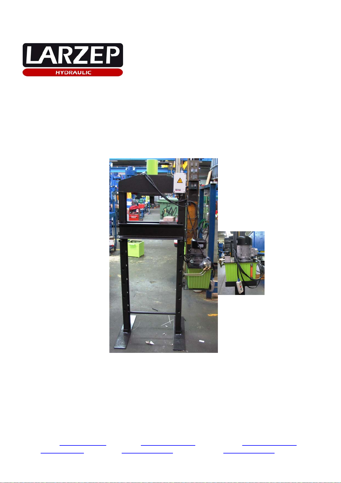
Column Press with Electric Pump “EE03116-CE”
FRAME: Welded-Mechanized frame, mobile table and anchor bolt system.
MODEL EE03116-CE
Max. working height (mm) 930
Min. working height (mm) 30
Sequence of bed positioning (mm) 150
Working width (mm) 500
Total weight (Kg) 135
3. ESSENTIAL SAFETY REQUIREMENTS.
Due to the functional reasons, "dangerous area" is considered to be the space between the columns, the bed and the hydraulic cylinder piston.
Due to the material pressed, "dangerous area" is supposed to be the surrounding area to the machine in case of metal parts being ejected during
pressing.
The speed of the hydraulic cylinder during its extension is less than 30 mm/second. Therefore the machine should be considered by the application of ANNEX V
of the Declaration of CE Conformity.
Operators standing in the dangerous area around the machine should protect their faces and feet form metal pieces being ejected during pressing.
Used materials and components are not dangerous for the health and safety of operators. The electric pump contains hydraulic oil type ISO: HV46
In any case, the hydraulic oil is toxic if it takes contact in the bloodstream, so that NEVER PLACE THE FINGERS OVER ANY HOLE THAT MAY
CAUSE A FILTRATION.
The start and stop operations of the motor is made with the commands of IP55 electric box. The commands are supplied with a 24 V. tension.
The advance and return movements of the cylinder are made by the hand lever located in the pump. This lever actuates over a directional valve.
The command have not maintaining action device due to the kind of operation that the equipment makes, the operator sometimes must place its hands
over the material to be treated. So that it forces to the operator to know the inherent risks and operating of the equipment.
The starting up of the motor is carried out by the green button located on the electric box.
The rest of operating devices are activated manually from the directional valve on the cover of the pump.
To get cylinder movements, it is necessary to push the green button.
The red emergency push button stops the machine completely, in a safe way. To re-start it is necessary to unblock the emergency button.
It can be stopped too from the remote control.
If you stop pressing the green push button, the motor stops and with it the cylinder movements.
The machine is equipped with the fuse and a thermo-magnetic switch for its protection.
The machine is equipped with supporting plates in the columns for a perfect stability. The machine gets operated without fixing onto the floor, but it is
strongly recommended to do it by drilling the plates in the place of your choice.
The construction of machine has been calculated to bear without any breaking under conditions of foreseen utilization and for the whole life of the
machine.
The hydraulic components have been designed and calculated in compliance with the ANSI B30.1
It is operator's responsibility to wear special protective clothes and attachments in both feet and face to prevent any damage as a result of accidental
fallings and breakings of metal pieces under operation or machine components in touch with.
Risks due to surfaces, bends and angles: The frame of the machine does not cause to be dangerous in that sense.
oRisk due to mobile components in the setup stage: The table can be positioned in several fixing points. In the EE03116 model, the
movement of the table must be performed manually (weight of the table 21, 5 Kg). It is operator's responsibility to wear safety shoes in any
case.
oRisk due to mobile components during service: The operator must either move the directional valve lever to "C" position or leave pushing
the remote control to stop the advance of the piston of the hydraulic cylinder. It can be stopped too with the red button head in the switch box
to fully stop the movement of the piston.
SAFETY PREVENTIVE ACTIONS AGAINST OTHER RISKS
Risk due to power supply: The machine is equipped with the fuse and a thermo-magnetic switch for its protection.
Risk due to hydraulic power: The hydraulic pump is equipped with an internal security valve in the tank, out of operator's control and rated at 700 bar,
as well as with a pressure relief valve on the tank cover adjustable by the operator (as per instruction in start-up chapter ) from 0 to 700 bar. The
hydraulic cylinder is also furnisher with a pressure relief valve, rated at 700 bar which prevents the retraction chamber of the cylinder from
overpressures in case of obstruction of the return way.
All the maintenance operations must be performed while the machine is stopped, thus avoiding this way any potentially dangerous situation.
A poor maintenance program of the press does not increase the risk, but obviously will revert in a lower performance.
The hydraulic pump is mounted in the frame and its access is very easy. To disassemble the pump, unscrew the bolts in the tap cover. In order to
disassemble the cylinder it is required to first disassemble the piping.
Isolation of the power supply: Release the terminal wiring to disconnect the power supply. Previously you should unplug the pin.
Handling by the operator: The machine is designed to assure that all maintenance tasks are performed by the operator in an easy and safe way. All the
components that would require any maintenance operation are easy accessible.
In the valve, you can find several marks depending on the position of the lever:
o"A" for extension of the cylinder piston.
o"B" for retraction of the cylinder piston.
o"C" for holding the pressure without piston movement.
The press, the cylinder and the electric pump have their corresponding serial numbers marked on them. In addition to it, you can find a sticker label showing the
commercial reference, capacity, working pressure, name and address of the manufacturer.