manuals.online logo
Brands
  1. Home
  2. •
  3. Brands
  4. •
  5. Euro Shatal
  6. •
  7. Power Tools
  8. •
  9. Euro Shatal RP3014E-50 Guide

Euro Shatal RP3014E-50 Guide

RP3014E-50
OPERATING INSTRUCTIONS & SPARE PARTS LIST
REVERSIBLE PLATE COMPACTORS
OCTOBER 2016
UPDATED OCT. 2017
Sales office and Warehouse:
Euro Shatal ApS
Murervej 5
DK-6710 Esbjerg V , DENMARK
Tel:(+45) 75168411
Fax: (+45)75168412
E-mail:euroshatal@shatal.com
www.shatal.com
Euro Shatal Deutschland GmbH
Wernher von Braun Str.3
D-86368 Gersthofen ,GERMANY
Tel:(+49) 8214609580
Fax:(+49)8214609581
E-mail:info@euroshatal.biz
www.euroshatal.de
RP3014E-50
-1-
Oct, 2016
Josef Levy
Murervej 5 GENERAL MANAGER
DK-6710 Esbjerg V , Denmark
Tel:(+45) 75168411
Fax: (+45)75168412
E-mail:euroshatal@shatal.com
Esbjerg V, October 2008
ENGLISH
CE DECLARATION OF CONFORMITY
We hereby declare that the equipment described below conforms to the relevant fundamental safety and health requirements of the appropriate CE Directives, both in its basic design
and construction. This declaration will cease to be valid if any modifications are made to the machine without our expressed approval.
Product: Vibratory Plate Compactors : RP3014E-50
The said product has been sound tested per Directive 2000/14/EC
Conformity Assessment Procedure
Measured sound power level
Guaranteed sound power level
Annex VI
103 dB(A)
105 dB(A)
Relevant CE Machinery Safety Directives :2006/42/EC, 2004/108/EC, EN500-1, EN500-4, 2000/14/EC
Appropriate internal measures have been taken to ensure that series-production units conform at all times to the requirements of current CE Directives and relevant standards.
The signatories are empowered to represent and act on behalf of the company’s management.
DANSK
CE OVERENSTEMMELSESDEKLARATION
Vi erklærer hermed, at det nedenstående produkt er fremstillet i overenstemmelse med de tilhørende og fundamentale sikkerheds- og sundhedsbetingelser fra de behørige CE direktiver,
både i dets grundliggende formgivning og konstruktion. Denne deklaration vil ophøre med være gyldig, hvis der bliver foretaget nogen som helst ændring på maskinen uden vores
tydelige tilladelse.
Produkt: Frem/bak-pladevibrator : RP3014-50
Dette produkt er blevet støjtestet jf. direktiv 2000/14/EC
I overenstemmelse med vurderingsprocedure
Målt lydstyrkeniveau
Garanteret lydstyrkeniveau
Annex VI
103 dB(A)
105 dB(A)
Relevant CE maskinsikkerhedsdirektiv : 2006/42/EC, 2004/108/EC, EN500-1, EN500-4, 2000/14/EC
Der er foretaget interne forholdsregler for at sikre, at produkter, der er fremstillet i serieproduktion, altid efterlever foreskrifterne fra gældende CE direktiver og relevante standarder.
Underskriverne har tilladelse til at representere og handle på vegne af firmaets ledelse.
DEUTSCH
CE BESTÄTIGUNG VON DEKLARATION
Wir erklären, dass das beschreibene Produkt sich an die relevante, fundamentale Sicher- und Gesundheits-behörden in die passende CE Direktiven richten, auch in seinem
grundsätlichen Design und Konstruktion. Diese Deklaration verliert seine Gültigkeit, falls irgend eine Modifikation auf der Maschine ohne unsere Zulassung gemacht wird.
Produkt: Rüttelplatte - Modell : RP3014-50
Das genannte Produkt ist von der Direktiv 2000/14/EC getestet worden
Gemäss Prozedure
Gemessen Lautstärke
Garantierte Lautstärke
Annex VI
103 dB(A)
105 dB(A)
Relevante CE Maschienesicherheitsdirektiven : 2006/42/EC, 2004/108/EC, EN500-1, EN500-4, 2000/14/EC
Wir haben interne Vorsichtsmassnahmen genommen, die Einheiten der Serienproduktion immer laut die Verlangen der laufenden CE Direktiven zu sichen und die relevanten Standarden
zu erfüllen.
Die Signaturen sind in Auftrag der Management der Firma representiert.
PORTUGUÊS
CE DECLARAÇÃO DE CONFORMIDADE
Nós declaramos que o equipamento abaixo descrito está conforme o fundalmental e relevante das normas de construção e segurança das Directivas CE apropriadas. Esta declaração
cessa a validade se alguma modificação for efectuada na máquina sem a nossa expressa aprovação.
Produto: Placa Vibratória Compactora : RP3014-50
O referido produto foi testado no nivel de ruido em conformidade com a Directiva 2000/14/EC
Procedimento de avaliação de conformidade
Nivel de potência sonora medido
Nivel de potência sonora Garantido
Annex VI
103 dB(A)
105 dB(A)
Directivas CE de segurança máquina relevantes : 2006/42/EC, 2004/108/EC, EN500-1, EN500-4, 2000/14/EC
Medidas internas apropriadas foramtomadas para assegurar que esta série/produção está sempre conforme os requirementos das Directivas CE correntes e outras Satandard. Os
signatários foramautorizados a representar e assinar em representação da companhia assinada.
RP3014E-50
-2-
Oct, 2016
SAFETY INSTRUCTION- QUICK GUIDE
SIKKERHEDS INSTRUKTIONER- Forkortet udgave
SICHERHEITSINSTRUKTIONEN- Kurzausgabe
VEILIGHEIDSINSTRUKTIES- Korte uitgave
INSTRUCCIONES DE SEGURIDAD - GUIA RAPIDA
ENGLISH
•Laws governing safety aspects on machinery may vary between countries but the following guides will useful to all operators:
•Before starting, carefully read the machine maintenance and operating manual and follow all the instructions.
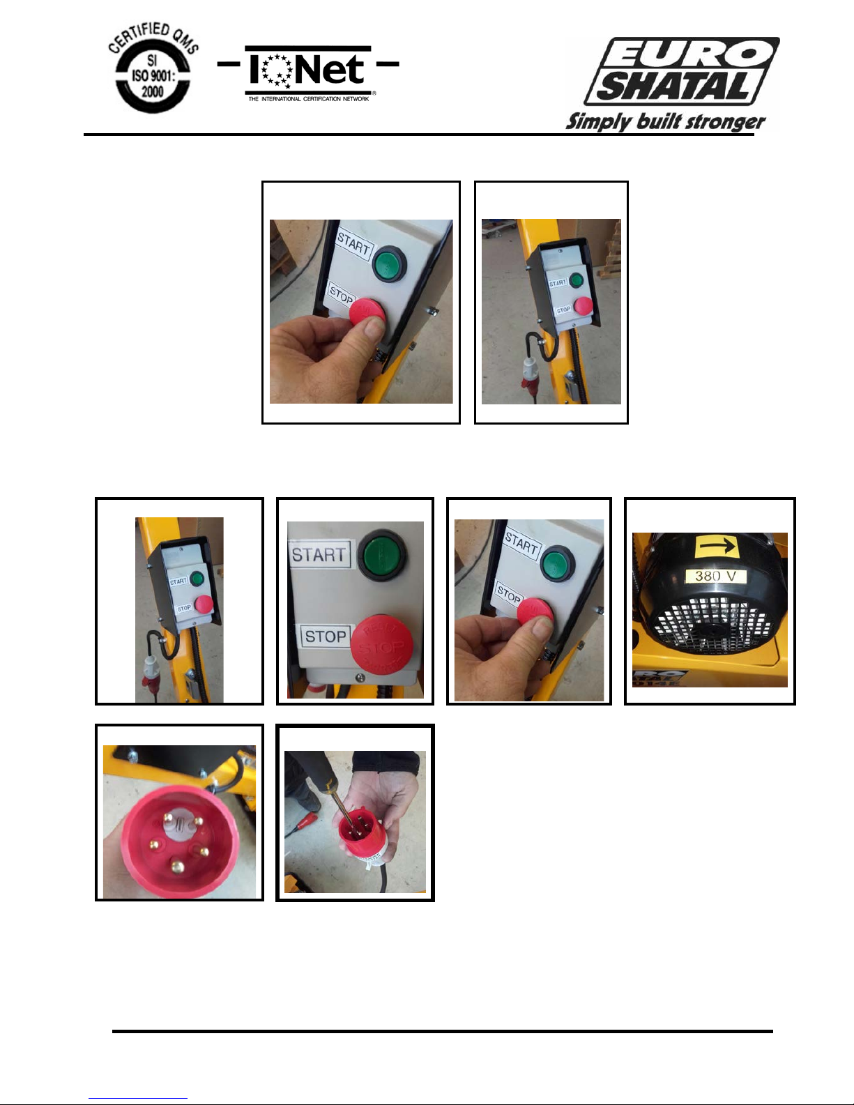
•Connect to three phase electric power socket, with 16 A, 380 V.
•In case of electrical outage, turn the operation switch off before further operation.
•Turn the operation switch off, after all machine use.
•Never operate the machine without the belt guard.
•Keep hand and feet away from moving parts while the machine is running.
•Operating the machine is advisable only with good lighting conditions.
•Hearing protection must be worn.
•Foot protection must be worn.
•Do not touch hot surfaces.
DANSK
•Sikkerhedslovgivningen på maskiner kan være forskellige landene imellem, men de følgende retningslinier er nyttige for alle operatører.
•Før start, venligst læs maskinens service og brugsanvisning, følg alle instruktioner nøje.
•Brug aldrig maskinen uden remskive beskyttelse.
•Hænder og fødder skal holdes væk fra alle bevæglige dele når maskinen kører.
•Brug ikke maskinen i lukkede rum, eller ved brandfarlige områder.
•Anvend maskinen kun når der er god belysning.
•Høreværn er altid påbudt.
•Sikkerhedssko er altid påbudt.
•Rør aldrig ved varme flader.
DEUTSCH
•Die Sicherheitsgesetze für Maschinen kønnen verschiden sein, aber die folgende anleitungen sind für alle operatoren verwändlich.
•Vor Arbeitsbeginn bitte Bedienungs – und Wartungsanleitung sorgfältig lesen und allen Empfehlungen folgen.
•Bitte die Maschine nie ohne Keilriemengehäuse benutzen.
•Bitte Hände und Füsse entfernt halten von allen beweglichen Teilen während die Maschine läuft.
•Bitte die Maschine nicht in feuergefährlichen oder geschlossenen Räumen benutzen.
•Bitte nur die Maschine benutzen wenn eine gute Beleuchtung vorhanden ist.
•Gehörschutz muss immer getragen werden.
•Sicherheitsschuhe müssen immer getragen werden.
•Heisse Flächen bitte nicht berühren.
DUTCH
•Wetgeving inzake veiligheidsaspecten van machines kunnen verschillen naargelang het land. Volgende gids kan door iedere gebruiker
gebruikt worden.
•Voor het starten zorgvuldig de instruktiehandleiding doorlezen, alle instrukties moeten gevolgd worden.
•Nooit de machine gebruiken zonder V-snaarbescherming.
•Houd altijd handen en voeten weg van bewegende delen terwijl de machine loopt.
•Gebruik de machine niet in gesloten en brandgevaarlijke ruimtes.
•Gebruik alleen de machine bij goede verlichting.
•Gehoorbescherming moet altijd gedragen worden.
•Veiligheidsschoenen moeten altijd gedragen worden.
•Nooit warme vlakken aanraken.
PORTUGUÊS
•Antes do arranque, leia com atenção o manual de operação e manutenção do motor e siga todas as
Instruções.
•Nunca opera a máquina sem a guarda da correia.
•Não utilize o aparelho em locais fechados e ambientes inflamáveis.
•Use gasolina sem chumbo.
•Pare o motor antes de encher o tanque de combustível. Nunca reabastecer perto de uma chama, ou faíscas, que poderiam
começar um incêndio. Não fume. Use somente combustível puro e limpo no enchimento dos equipamentos. Tome cuidado de
não derramar combustível.
•Antes de arrancar o motor certifique-se que não está ninguém na area perigosa próximo do motor ou equipamento, e que as
guardas de protecção estão colocadas.
•É aconselhável operar a máquina em boas condições de iluminação.
•Protecção auricular deve ser usada.
•Protecção aos pés deve ser usada.
RP3014E-50 - 3 - Oct, 2016
TECHNICAL SPECIFICATIONS
MODELS
Cat. No.
RP3014E-50
WEIGHT
Net Weight
kg.
196
COMPACTION DATA
Vibr. Frequency
Hz
81
Centrifugal Force kg.
3000
Compaction Area
m²/hour
600
OPERATION DATA
Max. Traveling speed
m/min
20
CAPACITIES
Oil for gear box liters
SAE 15W/40
1.0
DRIVE MOTOR
Output
HP
5.5
Engine speed
rpm
2840
NOISE AND VIBRATIONS
Sound power level according to ISO 5349 (*)
Measured sound power level
LwA=dB(A)
103
Vibration values
a=m/s²
The hand – arm vibration values according to ISO 5349
2.3
(*) The above noise level and vibration values were determined at normal speed of the engine.
RP3014E-50 -4- Oct, 2016
HANDLE IN THE WORKING POSITON
HANDLE IN THE FOLDING POSITON
MODEL
A
mm
B
Working Position
mm
B
Folding Position
mm
C
mm
D
mm
E
Working Position
mm
E
Folding Position
mm
RP3014E-50
710
1230
770
750
500
1150
1140
DIMENSION
RP3014E-50 -5-Oct, 2016
TRANSPORT TO WORK SITE :
•To avoid burns or fire hazards,let engine cool before transporting machine or storing indoors.
•Tie the machine to the vehicle to prevent sliding or tipping over.
INSTRUCTION FOR LIFTING MACHINE: SEE PICTURES 11 PAGE 7
•Never walk or stand under a machine being lifted.
•Use only the frame lifting hook (1) for lifting the machine.
•Use only tested and authorised lifting equipment. Before lifting check that vibration damper and protecting
frame are correctly attached and not damaged.
OPERATION:
SAFETY CHECK BEFORE CONNECTING THE MOTOR POWER CABLE TO A POWER SOURCE- SEE
PICTURES 1-2 PAGE 7
1. Press the stop button on the operation switch. (as shown in picture 1).
2. Connect the power cable to a 3 phase 16A 380V power source. (as shown in picture 2).
MOTOR WORKING DIRECTION TEST - SEE PICTURES 3-8 PAGE 7
1. Connect the power cable to a 3 phase 16A 380V power source (as shown in picture 3).
2. Check that the stop button isn’t compressed or rotated
3. Press the start button on the operation switch momentarily and immediately press the stop button on the
operation switch (as shown in picture 4,5).
4. Check the motor rotation direction. If the motor rotates in the same direction as the arrow (shown in picture 6),
than the motor is rotating in the working direction and can be operated safely. If the motor rotates in the
opposite direction as the arrow (shown in picture 6), then the phase inversion switch must be rotated 180
degree’s with a flathead screwdriver (as shown in pictures 7,8). The motor should now be operating in the
working direction and can be operated safely.
Note:
Only operate the motor in the working direction
Check the working direction every time the motor power cable is plugged into a new power
source that hasn’t been checked.
TURNING ON THE MOTOR-SEE PICTURES 9-10 ON PAGE 8.
1. Connect the power cable to a 3 phase 16A 380V power source (as shown in picture 9).
2. Check that the stop button isn’t compressed or rotated
3. Press the start button on the operation switch (as shown in picture 10)
OPERATING THE MACHINE
1. Lower the handle to the working position.
2. Let the compactor progress at its normal speed while guiding it in a straight line.
3. Three or four passes depending on the material are normally required to achieve the best compaction.
4. The soil must be moist to achieve the best compaction.
5. It must not be too wet nor too dry so that dust is created.
6. Do not operate the compactor on hard surfaces or concrete.
7. Attach a polyureathane plate under the compactor when compacting paving stones.
STOPPING THE MOTOR - SEE PICTURES 11,12 ON PAGE 8
1. Press the stop button on the operation switch. (as shown in picture 11).
2. Disconnect the power cable (as shown in picture 12).
RP3014E-50 -6- Oct, 2016
IMPORTANT ADVICE :
The manufacturer declines all responsibility for loss or damage resulting from misuse or any modification
or alteration that does not conform to the manufacturer’s original specifications.
At the workstation, the sound pressure level may exceed 85 db (A). In this case individual protection
measures must be taken
SPARE PARTS ORDERING :
When ordering spare parts, please mention machine serial no., part no. and description.
SCRAPPING :
In the event of deterioration and scrapping of the machine, the following items must be disposed of in
accordance with the requirements of the legislation in force.
Main Materials:
1. Motor : Aluminium (AL), Copper (CU), Polyamide (PA)
2. Machine : Steel sheet (AC)
MAINTENANCE SCHEDULE :
Check all external screw connections for tight fit approx. 8
hours after first operation.
Parts
Maintenance
Maintenance
interval
General
Remove all dirt, stones etc.
from the compactor after each
day of operation..
daily
Belts
Check tension and wear –
replace if necessary.
weekly
Motor
See Motor manufacturers
handbook
MAINTENANCE :
Monthly maintenance:
•Perform maintenance work on Motor according manufacturer’s instructions.
•Check belt tightness and tighten if necessary.
Belts should be move 10 –15 mm when pushed by the thumb.
•Check and retighten bolts and nuts.
The instructions for use and spare parts found in this document are for information only and are not binding. As part of our product quality improvement policy, we reserve
the right to make any and all technical modifications without prior notice.
RP3014E-50 - 7- Oct, 2016
SAFETY CHECK BEFORE PLUGGING IN THE MOTOR
1.
2.
MOTOR WORKING DIRECTION TEST
3.
4.
5.
6.
7.
8.
RP3014E-50 - 8- Oct, 2016
OPERATING
9.
10.
STOPPING THE MOTOR
11.
12.
RP3014E-50 -9- Oct, 2017
Please State Machine Details in the Following Sequence:
Machine Serial Number
Part Number, Description and Quantity of Parts
Full Delivery Address
Manufacturers Liability and the Use of Genuine Spare Parts
Liability for this machine is accepted only when the machine is defective from the outset.
Liability is reduced or nullified in the event that the user fails to comply with the operating and
maintenance instructions and uses spare parts which are not guaranteed.
Contents
Vibratory plate---------------------------------------------------------------------------------------------- 10-12
Exciter--------------------------------------------------------------------------------------------------------- 13-14
Working handle--------------------------------------------------------------------------------------------- 15-17
Vulcalon Plate----------------------------------------------------------------------------------------------- 18
Schematic Diagram--------------------------------------------------------------------------------------- 19
INSTRUCTIONS FOR ORDERING PARTS
WHEEL AXLE X2
47
45 46
16
21
31
48
30
34
33
37
38
40
41
42
43
44
12
29
26 23
22
21
20 18
19
17
15
14
13
12
11
9
10
8
6
3
2
1
RP3014E-50
4
27
39
1.1
32
25 24
28
35 36
12
7
5
OPTIONAL
VIBRATORY PLATE
55
56
UPDATED OCT.2017
54 57
-10-
51
52
50
48
53
49
OCT, 2016
Vibratory plate
RP3014E-50 -11- Oct, 2017
No.
Part No.
Qty.
Description
No.
Part No.
Qty.
Description
1 11402120 1 Baseplate for RP3014-50 26 11402145 1 Engine base
2 40527.2 4 Shockmount 27 ------------- 2 Hex. Head screw
3 11402156 1 Connecting plate 28 ------------- 2 Lock washer
4 ------------- 8 Hex. Head screw 29 I50512 1 5.5 HP motor
5 ------------- 8 Lock washer 30 ------------- 4 Hex. Head screw
6 ------------- 2 Hex. Head screw 31 11401223 4 Rubber cover for hatz cage
7 ------------- 2 Lock washer 32 11401199 4 Rubber top plate for cage
8 11401170 1 Handle 33 11402170 1 Inner belt guard
9 1110198 1 Nipple 34 ------------- 3 Hex. Head screw
10 11401903 1 Hydraulic pipe 35 ------------- 3 Lock washer
11 11402188 1 Right cover 36 ------------ 3 Washer
12 11401917 10 Hex. Flange bolt with teeth 37 P50754 1 Centrifugal clutch
13 11402184 1 Cover joining plate 38 11403923 1 Washer
14 11401915 2 Hex. Flange bolt with teeth 39 116901 1 Schnorr locking disc spring
15 11401197 1 Handle locking pin 40 ------------- 1 Hex. Head screw
16 11401204 1 Handle locking bush 41 508957 1 Belt
17 11401914 1 Spring 42 ZGS90107 1 PVC Seal
18 ------------- 1 Nut 43 11402161 1 Belt guard
19 11401198 1 Knob 44 11402159 1 Left cover
20 11402165 1 Protective frame 45 11101788 1 Belt guard seal
21 11403901 6 Hex. Flange bolt with teeth 46 11401221 1 Belt guard rubber spacer
22 11402172 1 Bracket 47 P11401195 1 Wheel axle
23 ------------- 2 Hex. Head screw 48 11402183 1 Base Plate
24 ------------- 2 Lock washer 49 ------------- 4 Hex Nut
25 ------------- 2 Washer 50 ------------- 4 Washer
51 ------------- 4 Schnorr locking disc spring
Vibratory plate
RP3014E-50 -12- Oct, 2017
No. Part No. Qty. Description
52 ------------- 1 Key
53 11402210 1 Protective cover box
54 50659 1 Enclosure BCI 2 Danfoss 047B010266
55 50657 1 Overload TI 16C Danfoss 047H0210
56 50660 1 Auxilary Co CB-S Danfoss 037 H0110
57 50658 1 Contactor CI 12 Danfoss 03H003137
MAIN SHAFT
EXPLODE VIEW
1
2
4
8
5
6
7
9
10
11
12
13
14
20
18
17
16
15
19
17
19
21
22
23
34
37
35 36
38
SECONDARY SHAFT
EXPLODE VIEW
1
25
17
19
26
27
28
26
17
19
25
32
31
30
29
19
33
EXCITER
OCT, 2016
-13-
RP3014E-50
Exciter
RP3014E-50 -14-Oct, 2016
No.
Part No.
Qty.
Description
No.
Part No.
Qty.
Description
1
See
Page-12
Baseplate for RP3014-50; RP3014-60 20 1110198 1 Hex. Flange Bolt with Teeth
2 11102815.U 1 Adjustmentgear 21 11401909 1 Oil Seal
3 2097927 Hex. socket set screw with cone point 22 11401222 1 Bearing cover
4 11401210 Main Shaft 23 129964 1 Key
5 11402177 2 Eccentric Weight 24 11102822.U 1 Pulley
6 11401916 4 Schnorr locking disc 25 11401218 2 Closed flange
7 110061 4 Hex. Soc. Head cap screw
26 110060 2 Retaining rings for shaft
8 11401910 1 Pin
27 11102813.U 1 Pulley
9 11401211 1 Bearing housing
28 11401216 1 Secondary Shaft
10 ----------- 1 Hex. Head screw
29 11401908 1 Key
11 110056 Schnorr locking disc
30 11402178 2 Eccentric Weight
12 11102802.U 2 Bearing
31 111960 2 Schnorr locking disc
13 11401912 1 Retaining rings for bores
32 11401919 2 Hex. Soc. Head cap screw
14 11401212 1 Piston
33 11402133 1 Gear closing plate
15 11401911 1 O-ring
34 ----------- 1 Hex. Soc. Head cap screw
16 11401907 1 Oil Seal
35 ----------- 1 Locking washer
17 11102805 4 Bearing
36 ----------- 1 washer
18 11401219 1 Cylinder
37 11402192 1 pulley
19 11401915 28 Hex. Flange Bolt with Teeth
38 11402193 1 spacer
11
9
5
4
3
2
1
62
6
10
8
7
12
14
13
15
18
19.1
16
20
23 22 21
24
65
64
63
25
26
27
28
29
30
50
49
48
52
53
54
55
58
61
5657
5960
32
37 38
39
42 40
36
35
34
33
31
41
43
44
45
46
47
51
19
15.1
30.1
46.1
43.1
60.1
SEE PISTON
SHAFT ASSEMBLY
37.1
64
65
RP3014E-50
-15-
M10 NUT
NUT M12
PISTON SHAFT ASSEMBLY
13
424038
39
36
37343332
31
WORKING HANDLE
OCT, 2016
Working Handle
RP3014E-50 -16-OCT. 2016
No.
Part No.
Qty.
Description
No.
Part No.
Qty.
Description
1 11401188
1 Right guide handle 22 ---------- 2 Self locking nut
2 31024 2 Nylon bush 23 11401175 1 Handle cover
3 11401181
1 Reverse handle shaft 24 11401918 4 Hex. Flange bolt with teeth
4
11401920
2
Plastic plug
25
1110395
1
Brass elbow
5 11401185
1 Left guide handle 26 ------------ 4 Hex. Head screw
6 111965 1 Key 27 11101814 1 Joining plate
7 ---------- 1 Self locking nut 28 1135903 1 O-ring
8 129968 1 Hex. socket set screw with cup point 29 11401183 1 Pump casing
9 1110154 1 Piston moving arm 30 11729 1 Oil plug
10 128940 1 Hex. socket set screw with cup point 30.1 1110198 1 Nipple
11
111908
1
Hex. socket head shoulder Screw
31
111934
2
Hydraulic seal
12 11101804
1 Connecting bar 32 1110134 1 Upper piston
13 11401184
2 Fork wheel 33 111140 1 Oil seal washer
14 --------- 1 Self locking nut 34 111933 1 Circlip
15 11401180
1 Oil tank plug 35 ---------- 1 Nut
15.1 11403919
1 O-Ring 36 11101907 1 Rubber bellow
16 ---------- 4 Hex. Head screw 37 1110193 1 Piston connecting bolt
17 ---------- 4 Washer 37.1 ---------- 1 Nut
18
11401179
1
Oil tank
38
11101912
1
Hex.thin nut
19
11403913
1
Brass washer
39
11101819
1
Nut
19.1
140905
1
Hex. Head cap screw
40
111931
1
Fork
20
11401177
2
Spacer
41
----------
Hex. Head screw
21 11401176
1 Bearing cover 42 111909 1
Hex. socket head shoulder Screw
Working Handle
RP3014E-50 -17-OCT. 2016
No.
Part No.
Qty.
Description
No.
Part No.
Qty.
Description
43 11401913
1 16mm dia. Tube clamp 60 ----------- 2 Lock washer
43.1 ------------- 1 Lock washer 60.1 ---------- 2 Washer
44
-----------
1
Nut
61
----------
2
Hex. Head screw
45 ----------- 1 Hex. Head screw 62 11401922 2 Self locking Hex. Bolt screw
46 11401905
1 8mm dia. Tube clamp 63 11401902 1 Hydraulic Hose
46.1 ------------- 1 Lock washer 64 111940 2 Pipe Clamp
47 ----------- 1 Nut 65 111938 2 Pipe Nipple
48 ---------- 1 Hex. Head screw
49 ---------- 1 Nut
50 111937 1 Shockmount
51 11401170
1 Handle assy.
52 11401182
1 Handle bottom shaft
53 31024 2 Nylon bush
54 111975 2 Shockmount
55 1110199 1 Plastic plug
56 ---------- 4 Hex. Head screw
57 110056 4 Schnorr locking disc spring
58 11401178
1 Stopper plate
59 ---------- 2 Hex. Head screw
Vulcolan Plate
RP3014E-50 -18- Oct, 2016
No. Part No. Qty.
Description
Beschreibung
Beskrivelse Descripción
1 1110306 1 Vulcolan plate RP3014-50 Vulkalonplatte RP 3014-50 Vulkolanplade RP3014-50 Plancha vulkolan RP3014-50
1.1 1110315 1 Vulcolan plate RP3014-60 Vulkalonplatte RP3014-60 Vulkolanplade RP3014-60 Plancha vulkolan RP3014-60
2 1110250 2 Vulcolan holder RP3014-50 Vulkalonhalter RP3014-50 Vulkolanholder RP3014-50 Agarradera de vulkolan RP3014-50
2.2 1110399 2 Vulcolan holder RP3014-60 Vulkalonhalter RP3014-60 Vulkolanholder RP3014-60 Agarradera de vulkolan RP3014-60
3 --------- 4 Hex. Head screw Sechskantschraube Skrue Tornillo hexagonal
4 --------- 4 Hex. nut Mutter Møtrik Tuerca hexagonal
Schematic Diagram
RP3014E-50 -19- Oct, 2017

Other Euro Shatal Power Tools manuals

Euro Shatal PC1114 User manual

Euro Shatal

Euro Shatal PC1114 User manual

Euro Shatal PC1443 User manual

Euro Shatal

Euro Shatal PC1443 User manual

Euro Shatal PC1614-50 User manual

Euro Shatal

Euro Shatal PC1614-50 User manual

Euro Shatal PC 1010 User manual

Euro Shatal

Euro Shatal PC 1010 User manual

Euro Shatal PC1214 User manual

Euro Shatal

Euro Shatal PC1214 User manual

Euro Shatal PC1443E User manual

Euro Shatal

Euro Shatal PC1443E User manual

Euro Shatal PC2014 User manual

Euro Shatal

Euro Shatal PC2014 User manual

Euro Shatal RP3014-50 Datasheet

Euro Shatal

Euro Shatal RP3014-50 Datasheet

Popular Power Tools manuals by other brands

Geo Knight Digital DK20 16x20 manual

Geo Knight

Geo Knight Digital DK20 16x20 manual

Bosch PMF Universal Original instructions

Bosch

Bosch PMF Universal Original instructions

Kemper 1060RC instruction manual

Kemper

Kemper 1060RC instruction manual

jbc advanced Series manual

jbc

jbc advanced Series manual

BASETech BT-2251517 operating instructions

BASETech

BASETech BT-2251517 operating instructions

CPS BLACKMAX BTLDTW manual

CPS

CPS BLACKMAX BTLDTW manual

Cleco 11PHH instruction manual

Cleco

Cleco 11PHH instruction manual

Flipper ZERO FZ.1 quick start

Flipper

Flipper ZERO FZ.1 quick start

BOSSTOP AMZHP230B user manual

BOSSTOP

BOSSTOP AMZHP230B user manual

Black & Decker GSL35 instruction manual

Black & Decker

Black & Decker GSL35 instruction manual

DeWalt XR LI-ION DCMAS5713 Original instructions

DeWalt

DeWalt XR LI-ION DCMAS5713 Original instructions

DeWalt DC820, DC830, DC840 user guide

DeWalt

DeWalt DC820, DC830, DC840 user guide

BLUM MINIPRESS top M70.2000 Safety instructions, set-up instructions and instruction leaflet

BLUM

BLUM MINIPRESS top M70.2000 Safety instructions, set-up instructions and instruction leaflet

Ingersoll-Rand 100SQ1 Operation and maintenance manual

Ingersoll-Rand

Ingersoll-Rand 100SQ1 Operation and maintenance manual

Fieldmann FDP 2001-E manual

Fieldmann

Fieldmann FDP 2001-E manual

Ayce 1328 Operator's manual

Ayce

Ayce 1328 Operator's manual

Bosch 0 601 9H5 100 Original instructions

Bosch

Bosch 0 601 9H5 100 Original instructions

Yokota TKA800 manual

Yokota

Yokota TKA800 manual

manuals.online logo
manuals.online logoBrands
  • About & Mission
  • Contact us
  • Privacy Policy
  • Terms and Conditions

Copyright 2025 Manuals.Online. All Rights Reserved.