Chigo CMV-R Serie User manual

INSTALLATION MANUAL
INSTALLATION
MANUAL
CMV-R Series
ALL DC Inverter Heat Recovery A/C
Thank you very much for purchasing our air conditioner!
This instruction manual is the universal version for ALL DC Inverter Heat Recovery A/C air conditioners, the appearance of your air conditioner may
be varying with the appearance of unit introduced in the manual, but it will not confuse you in operating and using.
Please read this manual carefully before using, and keep it for future reference.
To protect your lawful rights and interests, your air conditioner must be installed by a professional worker.
●
●
●
●
CE N TR AL AI R- CO ND I TION IN G

INSTALLATION
When installing the unit in a small room, take measures
against to keep refrigerant concentration from exceeding
allowable safety limits in the event of refrigerant leakage.
Contact the place of purchase for more information. Excessive
refrigerant in a closed ambient can lead to oxygen deficiency.
Use the attached accessories parts and specified parts for
installation.
Otherwise, it will cause the set to fall, water leakage, electrical
shock fire.
Install at a strong and firm location which is able to
withstand the set's weight.
If the strength is not enough or installation is not properly done,
the set will drop to cause injury.
The appliance shall not be installed in the laundry.
Before obtaining access to terminals, all supply circuits
must be disconnected.
The appliance must be positioned so that the plug is
accessible.
The enclosure of the appliance shall be marked by word, or
by symbols, with the direction of the fluid flow.
For electrical work, follow the local national wiring
standard, regulation and this installation instructions. An
independent circuit and single outlet must be used.
If electrical circuit capacity is not enough or defect in electrical
work, it will cause electrical shock fire.
Use the specified cable and connect tightly and clamp the
cable so that no external force will be acted on the
terminal.
If connection or fixing is not perfect, it will cause heat-up or fire
at the connection.
Wiring routing must be properly arranged so that control
board cover is fixed properly.
If control board cover is not fixed perfectly, it will cause heat-up
at connection point of terminal, fire or electrical shock.
If the supply cord is damaged, it must be replaced by the
manufacture or its service agent or similarly qualified
person in order to avoid a hazard.
An all-pole disconnection switch having a contract
separation of at least 3mm in a poles should be connected
in fixed wiring.
When carrying out piping connection, take care not to let
air substances go into refrigeration cycle.
Otherwise, it will cause lower capacity, abnormal high pressure
in the refrigeration cycle, explosion and injury.
Do not modify the length of the power supply cord or use
of extension cord, and do not share the single outlet with
other electrical appliances.
Otherwise, it will cause fire or electrical shock.
Carry out the specified installation work after taking into
account strong winds, typhoons or earthquakes.
Improper installation work may result in the equipment falling
and causing accidents.
1
Installation manual
Precautions before reading the Installation manual.
1. PRECAUTIONS
WARNING
WARNING
The safety precautions listed here are divided into two categories. In
either case, important safety information is listed which must be read
carefully.
After completing the installation, make sure that the unit operates
properly during the start-up operation. Please instruct the customer
on how to operate the unit and keep it trained. Also, inform
customers that they should store this Installation manual along with
the owner's manual for future reference.
Be sure only trained and qualified service personnel to
install, repair or service the equipment.
Improper installation, repair, and maintenance may result in
electric shocks, short-circuit, leaks, fire or other damage to the
equipment.
Install according to this installation instructions strictly.
If installation is defective, it will cause water leakage, electrical
shock fire.
Failure to observe a warning may result in death.
CAUTION
Failure to observe a caution may result in injury or damage
to the equipment.
This Installation manual is for the outdoor unit.
Refer to the indoor unit Installation manual for indoor parts
installation.
Please read the power source unit Installation manual to install
the power source unit.
Please refer to the refrigerant distributor Installation manual to
install the refrigerant distributor.
CONTENTS PAGE
1. PRECAUTIONSC..................................................................................1
2. CONSTRUCTION CHECKPOINTS..........................................................2
3. ACCESSORIES....................................................................................3
4. OUTDOOR UNIT INSTALLATION..........................................................3
5. REFRIGERANT PIPE............................................................................8
6. CONNECTING PIPE OF CS................................................................14
7. CS WIRING NAMEPLATE..................................................................14
8. ELECTRIC WIRING............................................................................15
9. TRIAL RUN
.........................................................................................21
2
Installation manual
Acceptance and Unpacking
After the machine arrives, check whether it is damaged during
the shipment. If the surface or inner side of the machine is
damaged, submit a written report to the shipping company.
Check whether the model, specification and quantity of the
equipment conform to the contract.
After removing the outer package, please keep the operation
instructions well and count the accessories.
Refrigerant pipe
Check the model and name to avoid mistaken installation.
An additionally purchased refrigerant distributor (manifold
adapter and manifold pipe) must be used for installing the
refrigerant pipes.
The refrigerant pipes must have the specified diameter.
Nitrogen of a certain pressure must be filled into the refrigerant
pipe before welding.
The refrigerant pipe must undergo heat insulation treatment.
After the refrigerant pipe is installed completely, the indoor unit
cannot be powered on before performing the airtight test and
creating a vacuum. The air-side and liquid-side pipes must
undergo the airtight test and vacuum extraction.
Airtight test
The refrigerant pipe must undergo the airtight test (with
40kgf/cm2nitrogen).
Creating a vacuum
Be sure to use the vacuum pump to create a vacuum of the
connective pipe at the air side and liquid side concurrently.
Refrigerant replenishment
If the length is greater than the reference pipe, the refrigerant
replenishment quantity for each system should be calculated
through the formula obtained according to the actual length of
pipe.
Record the refrigerant replenishment quantity, actual length of
pipe and the height difference of the indoor & outdoor unit onto
the operation confirmation table of the outdoor unit in advance
for future reference.
Electric wiring
Select the power supply capacity and wire size according to
the design manual. The power cable of the air conditioner is
generally thicker than the power cable of the motor.
In order to prevent misoperation of the air conditioner, do not
interleave or entwine the power cable with the connection
wires (low-voltage wires) of the indoor/outdoor unit.
Power on the indoor unit after performing the airtight test and
making a vacuum.
For details of setting the address of the outdoor unit, see
Outdoor unit address bits.
If the refrigerant leaks during installation, ventilate the area
immediately.
Toxic gas may be produced if the refrigerant comes into the
place contacting with fire.
After completing the installation work, check that the
refrigerant does not leak.
Toxic gas may be produced if the refrigerant leaks into the
room and comes into contact with a source of fire, such as a
fan heater, stove or cooker.
2. CONSTRUCTION CHECKPOINTS
CAUTION
This A/C is a kind of amenity unit. Don’t install it at the
place where for storing machine, precise instrument, food,
plant, animal, artwork or any other special used occasion.
Ground the air conditioner.
Do not connect the ground wire to gas or water pipes, lightning
rod or a telephone ground wire. Incomplete grounding may
result in electric shocks.
Be sure to install an earth leakage breaker.
Failure to install an earth leakage breaker may result in electric
shocks.
Connect the outdoor unit wires , then connect the indoor
unit wires.
You are not allowed to connect the air conditioner with the
power source until wiring and piping the air conditioner is done.
While following the instructions in this Installation manual,
install drain piping in order to ensure proper drainage and
insulate piping in order to prevent condensation.
Improper drain piping may result in water leakage and property
damage.
Install the indoor and outdoor units, power supply wiring
and connecting wires at least 1 meter away from
televisions or radios in order to prevent image interference
or noise.
Depending on the radio waves, a distance of 1 meter may not
be sufficient enough to eliminate the noise.
The appliance is not intended for use by young children or
infirm persons without supervision.
Young children should be supervised to ensure that they
do not play with the appliance.
Don't install the air conditioner in the following locations:
There is petrolatum existing.
There is salty air surrounding (near the coast).
There is caustic gas (the sulfide, for example) existing in the air
(near a hot spring).
The Volt vibrates violently (in the factories).
In buses or cabinets.
In kitchen where it is full of oil gas.
There is strong electromagnetic wave existing.
There are inflammable materials or gas.
There is acid or alkaline liquid evaporating.
Other special conditions.
The insulation of the metal parts of the building and the air
conditioner should comply with the regulation of National
Electric Standard.
3
Installation manual
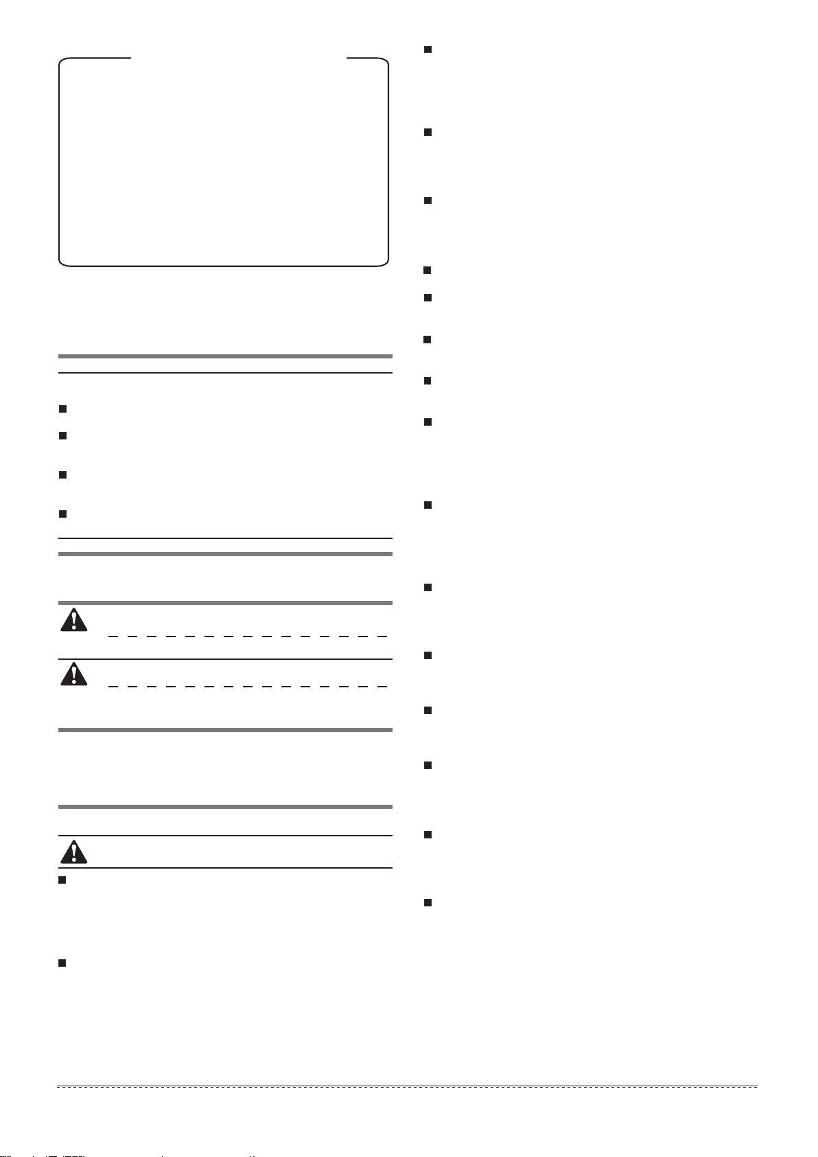
3. ACCESSORIES
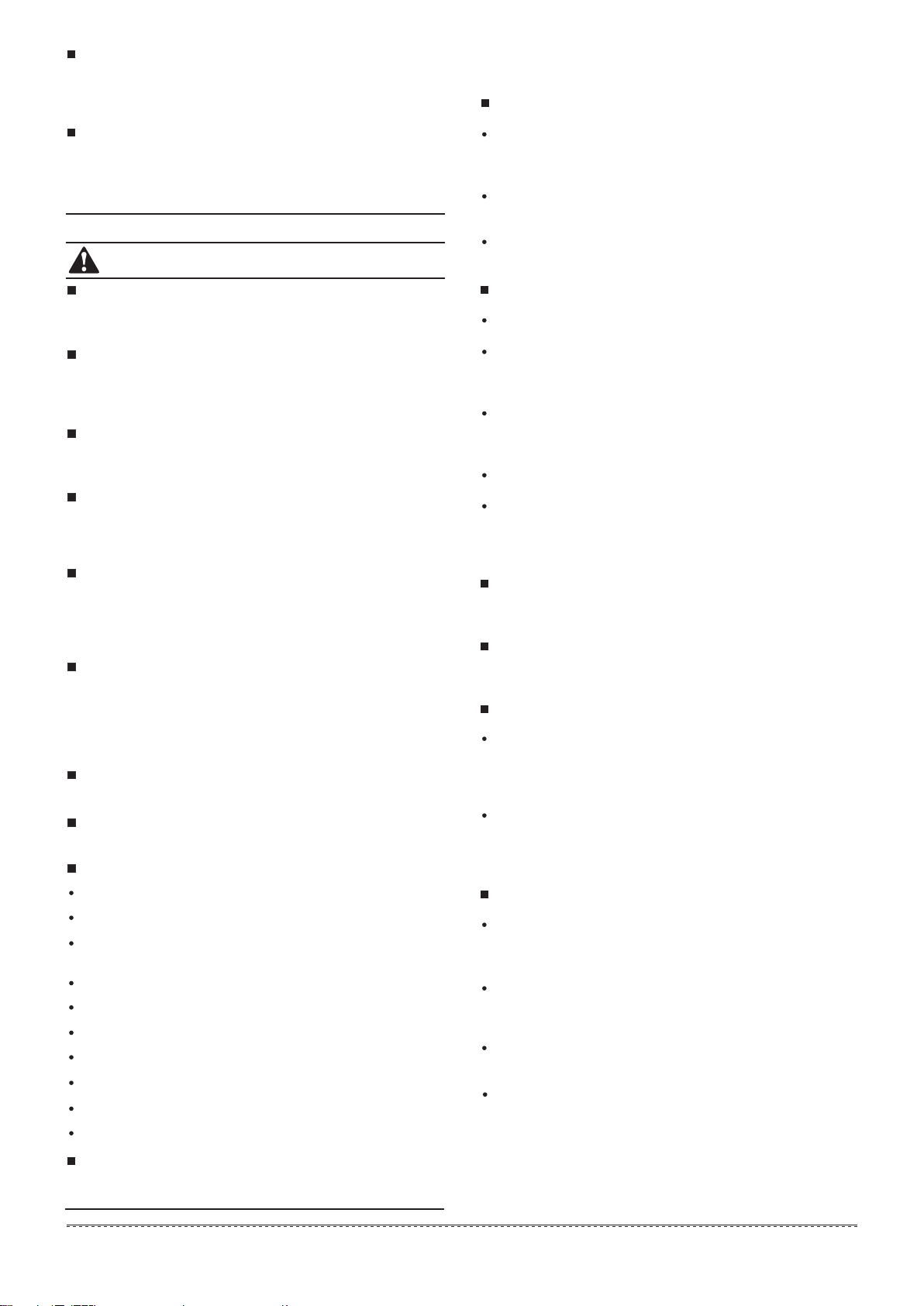
4.2 Dimension of outdoor unit
Trial run
Before operation, remove the four pieces of PE foaming which
are used at the rear of the unit for protecting the condenser. Be
careful not to damage the fin. Otherwise, the heat exchange
performance may be affected.
Perform the trial run only after the outdoor unit has been
powered on for over 12 hours.
4. OUTDOOR UNIT INSTALLATION
4.1 Outdoor unit combination
Function
Outdoor unit
installation manual
Outdoor unit
owner’s manual
Indoor unit
owner’s manual
Outdoor unit
branch pipe
installation manual
Installation manual
of indoor
manifold
VRF address
setting remote
controller manual
OutlineAll of units
Model
Name
1
1
1
1
1
1
1
1
Be sure to deliver
it to the customer
Be sure to deliver
it to the customer
Be sure to deliver
it to the customer
Be sure to deliver
it to the customer
Be sure to deliver
it to the customer
5
Table.3-1
Table.4-1
Connective pipe
accessory
Resistance
Power supply to the
remote controller
Connect to the
liquid pipe side
Connect to the
high-pressrue
gas balance side
Stored for service
(
used in 8HP~16HP
)
(
used in 8HP~16HP
)
1
Connective pipe
accessory
Connective pipe
accessory
Remote controller
2
Battery
Connect to the
low-pressure
gas pipe side
Address setting
1
16HP×3
14HP×2+16HP
14HP+16HP×2
64
64
64
44
46
48
Max Qty.of
indoor unit
ModeHP
Max Qty.of
indoor unit
Mode
HP
Table.4-2
10HP+14HP+16HP×2
14HP×3+16HP
14HP+16HP×3
16HP×4
14HP×2+16HP×2
64
64
64
64
64
56
58
60
62
64
8HP+10HP+16HP×2
10HP+12HP+16HP×2
10HP×2+16HP×2
64
64
64
50
52
54
Fig.4-1
Unit:mm
(
used in 10,12HP
)
4.3 Selecting installation position
Ensure that the outdoor unit is installed in a dry, well-ventilated
place.
Ensure that the noise and exhaust ventilation of the outdoor
unit do not affect the neighbors of the property owner or the
surrounding ventilation.
Ensure that the outdoor unit is installed in a well-ventilated
place that is possibly closest to the indoor unit.
Ensure that the outdoor unit is installed in a cool place without
direct sunshine exposure or direct radiation of high-temp heat
source.
Do not install the outdoor unit in a dirty or severely polluted
place, so as to avoid blockage of the heat exchanger in the
outdoor unit.
Do not install the outdoor unit in a place with oil pollution, salt
or high content of harmful gases such as sulfurous gas.
5910HP×2+16HP36
10HP+12HP+16HP
10HP+14HP+16HP
14HP×3
38 63
64
64
40
42
43
46
50
53
5610HP×2+14HP
10HP+16HP
14HP×2
14HP+16HP
16HP+16HP
26
28
30
32
34
36
39
10HP+12HP
10HP+14HP
22
24
88HP×1 13
16
20
23
26
29
33
10HP×1
12HP×1
14HP×1
16HP×1
8HP+10HP
10HP+10HP
10
12
14
16
18
20
Max Qty.of
indoor unit
ModeHP Max Qty.of
indoor unit
ModeHP
1260
1620
765

Fig.4-2
Fig.4-4
Fig.4-5
Fig.4-6
Installation manual
A solid, correct base can:
Avoid the outdoor unit from sinking.
Avoid the abnormal noise generated due to base.
Base types
Steel structure base
Concrete base (see the figure below for the general making
method)
Concrete basement
h=200mm
Outdoor unit
Φ10 Expansion bolt
Rubber shocking
proof mat
Solid ground
or roofing
200mm
Before construct the unit base, please ensure the base is
directly supporting the rear and front folding edges of the
bottom panel vertically, for the reason of these edges are the
actual supported sites to the unit.
In order to drain off the seeper around the equipment, a
discharge ditch must be setup around the basement.
Please check the affordability of the roofing to ensure the load
capacity.
When piping from the bottom of the unit, the base height should
no less than 200mm.
CAUTION
The key points to make basement:
The master unit’s basement must be made on the solid
concrete ground . Refer to the structure diagram to make
concrete basement in detail, or make after field measurements.
In order to ensure every point can contact equality, the
basement should be on completely level.
If the basement is placed on the roofing, the detritus layer isn’t
needed, but the concrete surface must be flat. The standard
concrete mixture ratio is cement 1/ sand 2/ carpolite 4, and add
Φ10 strengthen reinforcing steel bar, the surface of the cement
and sand plasm must be flat, border of the the basement must
be chamfer angle.
4
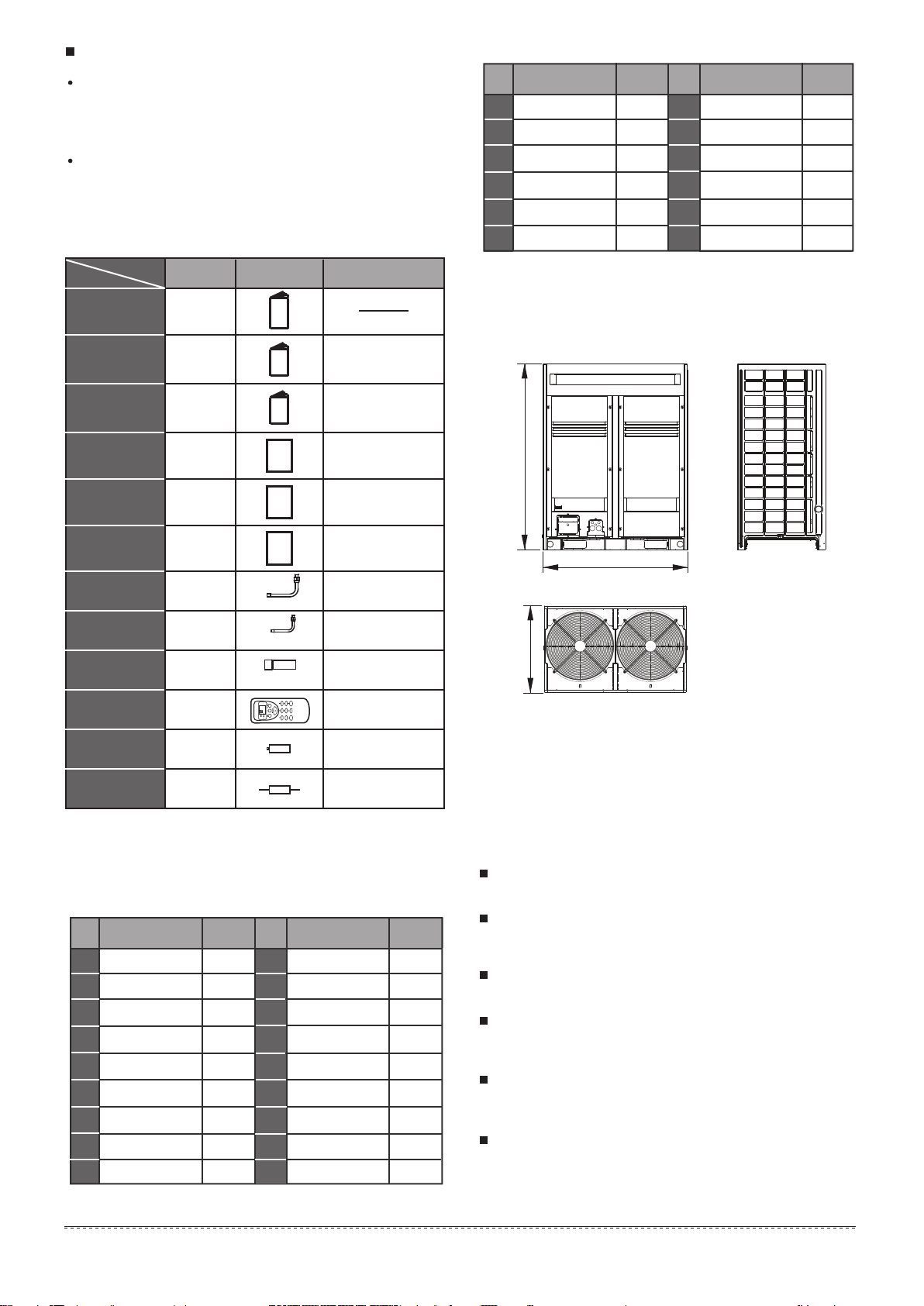
Centering position illustration of each connective pipe (Unit: mm)
1) 8HP,10HP
2) 12HP
Unit: mmTable.4-3
A
B
D
C
SIZE
HP
998
1302
703
817
8~16
Position illustration of screw bolt (Unit: mm)
Fig.4-3
15×23 long U-shape hole
B
A
C
D
R
For parallel
connection
The connective pipe
diameter Φ12.7
(by a reducer)
Oil balance valve
Liquid side of
shut-off valve
The connective pipe
diameter Φ19.05
The connective pipe
diameter Φ22
(by a reducer)
The connective pipe
diameter Φ19.05
High-pressure gas
side of shut-off valve
Low-pressure gas
side of shut-off valve
High-pressure
gas balance valve
R amplification
R
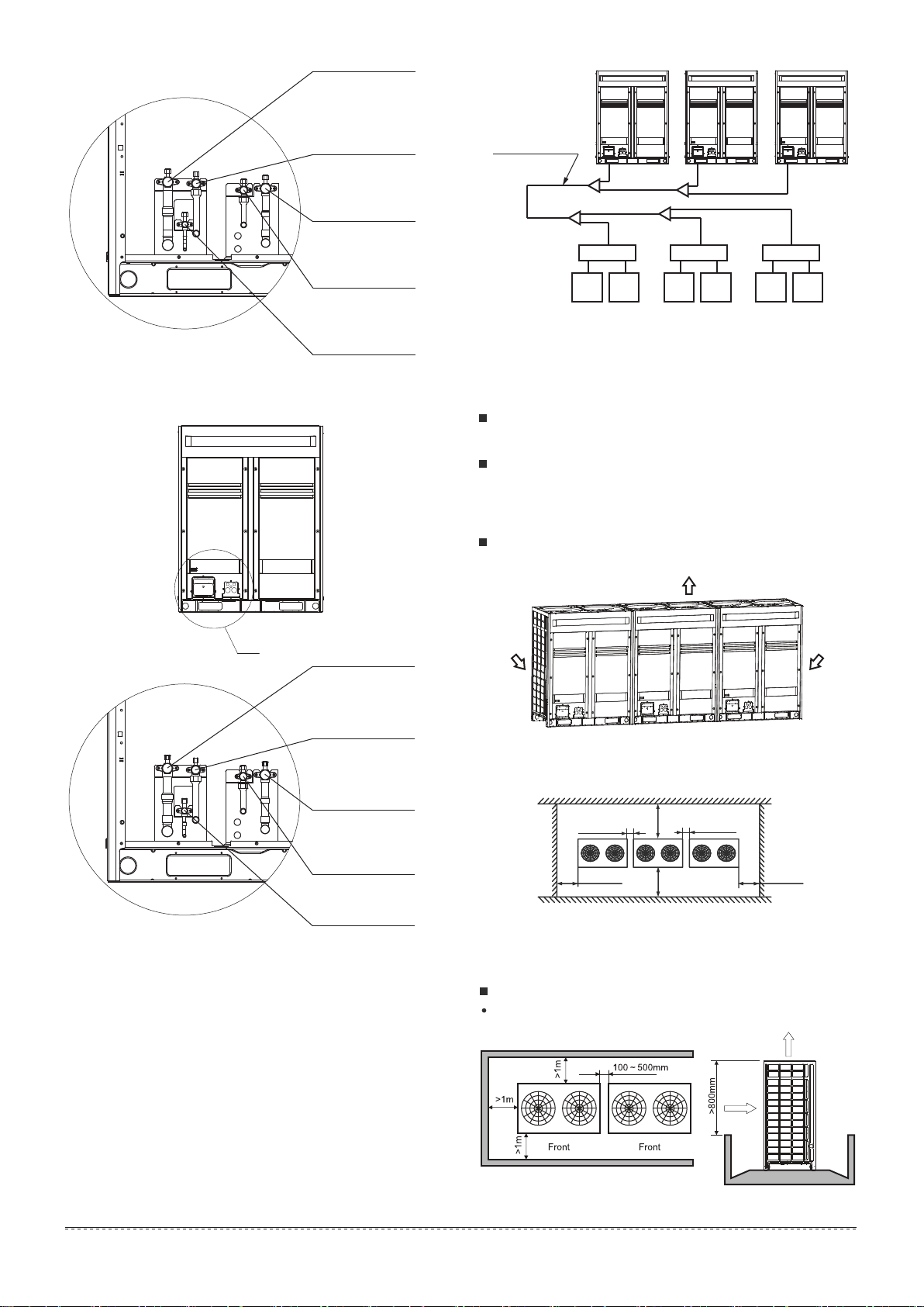
Fig.4-7
Fig.4-8
Fig.4-9
5
Installation manual
4.5 Outdoor units’ placement sequence &
master and slave units’ settings
A system, which provide with more than two outdoor units, will
be set as the followings method: The outdoor units in this
system should place sequentially from the large to the small
capacity; the largest capacity outdoor unit must be mounted at
unit address as the master Unit, while the other setting as the
Slave Unit. Take 38HP (composed by 10HP, 12HP and 16HP)
as an example:
1) Place the 16HP at a side of the first branch joint site.
2) Place the unit from the large capacity to the small (See the
detail placement illustration)
3) Set 16HP as the main unit, while the 12HP and the 10HP as
the aux. unit.
4.6 Installation space for outdoor unit
Ensure enough space for maintenance. The modules in the
same system must be on the same height.(see the Fig.4-11)
When installing the unit, leave a space for maintenance shown
in Fig.4-12..Install the power supply at the side of the outdoor
unit. For installation procedure, see the power supply device
Installation manual.
In case any obstacles exist above the outdoor unit, refer to
Fig.4-17.
Fig.4-13
4.7 Layout
When the outdoor unit is higher than the surrounding obstacle
One row
Fig.4-12
Top view of the outdoor unit
>1000mm
>1000mm
100~500mm
100~500mm
>1000mm >1000mm
Fig.4-11
(Air-out)
(Air-in)
(Air-in)
Installation and maintenance surface
Fig.4-10
3) 14HP,16HP
For parallel
connection
The connective pipe
diameter Φ12.7
(by a reducer)
Oil balance valve
Liquid side of
shut-off valve
The connective pipe
diameter Φ19.05
The connective pipe
diameter Φ25.4
(by a reducer)
The connective pipe
diameter Φ19.05
High-pressure gas
side of shut-off valve
Low-pressure gas
side of shut-off valve
High-pressure
gas balance valve
R amplification
R
For parallel
connection
The connective pipe
diameter Φ15.88
Oil balance valve
Liquid side of
shut-off valve
The connective pipe
diameter Φ22
The connective pipe
diameter Φ28.6
The connective pipe
diameter Φ19.05
High-pressure gas
side of shut-off valve
Low-pressure gas
side of shut-off valve
High-pressure
gas balance valve
R amplification
Outdoor unit
The 1st branch joint
16HP 12HP 10HP
(38HP)
CS
Indoor
unit D
Indoor
unit C
CS
Indoor
unit F
Indoor
unit E
CS
Indoor
unit B
Indoor
unit A

6
Installation manual
Fig.4-14
Two rows
Fig.4-17
When the outdoor unit is lower than the surrounding obstacle,
refer to the layout used when the outdoor unit is higher than
the surrounding obstacle. However, to avoid cross connection
of the outdoor hot air from affecting the heat exchange effect,
please add an air director onto the exhaust hood of the outdoor
unit to facilitate heat dissipation. See the figure below. The
height of the air director is HD (namely H-h). Please make the
air director on site.
If miscellaneous articles are piled around the outdoor unit, such
articles must be 800mm below the top of the outdoor unit.
Otherwise, a mechanic exhaust device must be added.
Fig.4-16
Fig.4-15
More than two rows
In snowy areas, facilities should be installed to prevent snow.
(See the figure below) (defective facilities may cause
malfunction.) Please lift the bracket higher and install snow
shed at the air inlet and air outlet.
Fig.4-18
4.8 Set the snow-proof facility
4.9 Explanation of valve
Table.4-4
Fig.4-19
Connect oil balance pipe
Connect liquid pipe
(accessory, field installation)
Connect high-pressure gas pipe
(accessory, field installation)
Connect low-pressure gas pipe
(accessory, field installation)
Connect high-pressure gas balance pipe(accessory, field installation)
Notes:16HP as an example
1
2
3
Fig.4-20
Fig.4-21
Example A
Installation illustration
4
5
B(mm)
B >
Airflow deflector
B
A
θ

7
Installation manual
Fig.4-22
Fig.4-23
Curve diagram of static pressure, air flow volumn.
Fig.4-27
Fig.4-28
Fig.4-29
Example B
NOTE
Before install the air deflector, please ensuring the mesh
enclosure has been took off, otherwise the air supply efficiency
would be block down.
Once mounting the shutter to the unit, air volume, cooling
(heating) capacity and efficiency would be block down, this
affection enhance along with the angle of the shutter. Thus, we
are not recommend you to mount the shutter, if necessary in
use, please adjust the angle of shutter no larger than 15°.
Only one bending site to be allowanced in the air duct (see as
above figure), otherwise, misoperation may led out.
Install the flexible connector between the unit and the air pipe,
for avoiding to produce vibration noise
Fig.4-24
8/10HP Air pressure curve diagram
(take down the mesher)
Static pressure (Pa)
Air volume
9500
10000
10500
11000
11500
12000
12500
0 5 10 15 20 25
Fig.4-25Static pressure (Pa)
Air volume
10500
11000
11500
12000
12500
13000
13500
0 5 10 15 20 25
12HP Air pressure curve diagram
(take down the mesher)
Fig.4-26Static pressure (Pa)
Air volume
12500
13000
13500
14000
14500
15000
15500
0 5 10 15 20 25
14/16HP Air pressure curve diagram
(take down the mesher)
Unit: mmTable.4-5
A≥300A
B
C
D
B≥250
C≤8000
600≤D≤760
θ≤15°θ
Unit: mmTable.4-6
A≥300A
B
C
B≥250
C≤8000
θ≤15°
θ
8
Installation manual
Fig.5-1
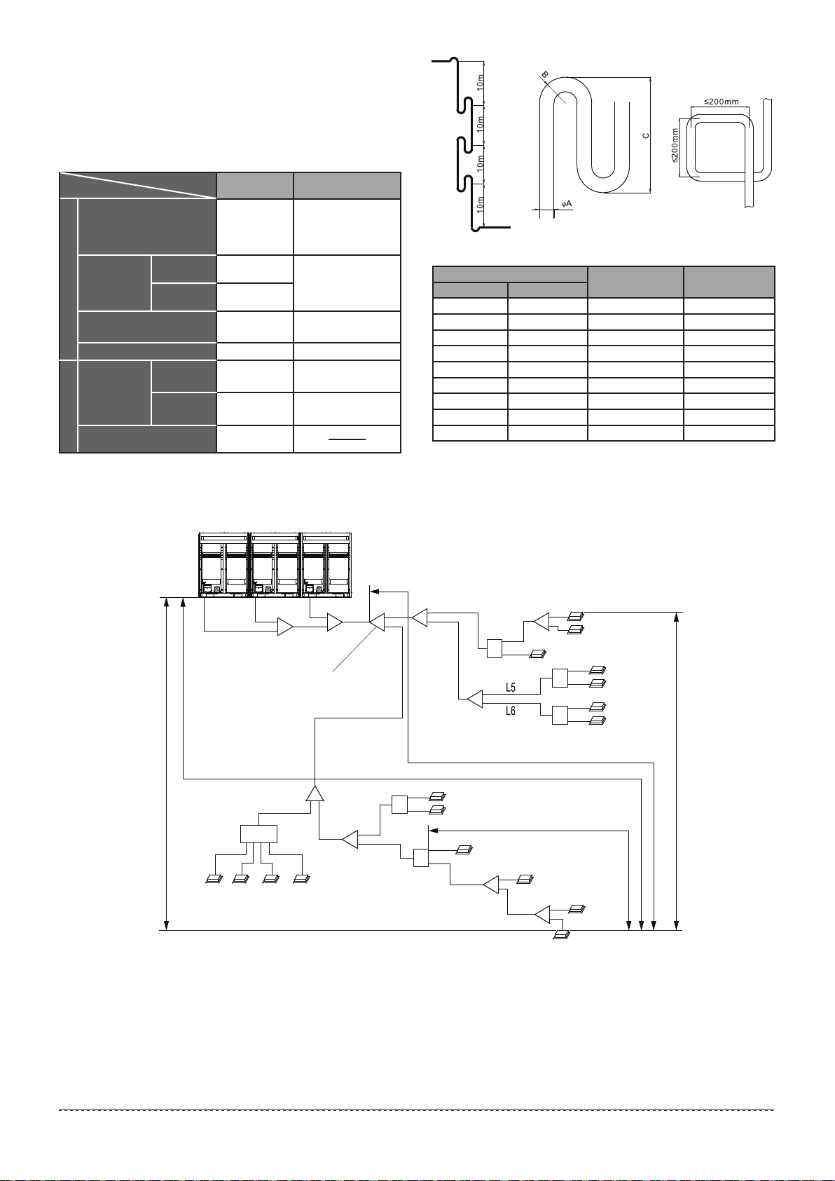
5.1 Length and drop height permitted of the
refrigerant piping
5. REFRIGERANT PIPE
Note: Assume equivalent pipe length of the branching pipe header to
be 0.5m,of the CS to be 1m(for calculation purposes).
Fig.5-2
Table.5-1
Permitted value
Piping
Total pipe length (Actual)
Indoor unit to indoor unit drop height
Piping (farthest from the first line
pipe branch) equivalent length
Pipe lengthDrop height
Equivalent length
Actual length
Maximum
piping (L)
outdoor unit up
outdoor unit down
Indoor unit to
outdoor unit
drop height
30m
40m
L1+
(
L2+L3+L4+L5+L6+
L7+L8+L9+L10+L11
)
×2+
a+b+c+d+e+f+g+h+i+j+k
+l+m+n+o+p+q+r+s+t
L1+L7+L9+L11+l+n+p
L7+L9+L11+l+n+p
l+n+p
CS to indoor unit equivalent lengthequivalent length
1000m
(Please refer to
the caution 5 of
conditions 2)
175m
200m(Please
refer to caution 1)
(Please refer to
caution 3)
(Please refer to
caution 4)
40m/90m(Please
refer to caution 5)
70m
110m
Oil return bend
Φ19.05
Φ28.6
Φ25.4
Φ22.2
Φ34.9
Φ38.1
Φ41.3
Φ44.5
Φ54.1
A
Mm Inch
B
mm( )
C
mm( )
3/4
7/8
1/1
9/8
11/8
12/8
13/8
14/8
17/8
≥34
≥36
≥45
≥55
≥60
≥60
≥80
≥80
≥90
≤150
≤150
≤150
≤150
≤250
≤350
≤450
≤500
≤500
Mode 1 Mode 2
Indoor unit
Outdoor unit
(one or more outdoor units)
(From the first line branch pipe) Maximum
piping equivalent length L≤40m/90m
Max piping equivalent length L≤200m
CS to indoor unit equivalent length L≤40m
The first line branch pipe
Drop height between indoor
unit and outdoor unit H≤110m
indoor unit to indoor unit
drop height H≤30m
N17N16
(140)(56)(28) (28)
N15N14
q r s t
CS6
L8
L9 L10
L11
D
E
CS4
CS5
i
j
k
lm
no
p
N11(28)
N12(56)
N13(56)
N8(71)
N9(71)
N10(140)
g1 g2 g3
G1
MLL1 A
L7
L2 B
L3
L4
CS1
a
b
c
de
f
g
h
C
N1(71)
N2(71)
N3(28)
N4(56)
N5(28)
N6(71)
N7(71)
CS2
CS3
Ⅰ
Ⅱ
Ⅲ

9
Installation manual
5.2 Select the refrigerant piping type
Fig.5-3
CAUTION
The reduced length of the branch joint is the 0.5m of the equiva-
lent length.
The inner units should as equal as possible to be installed in the
both sides of the U-shape branch joint.
When the outdoor unit is on the top position and the difference of
level is over 20m, it is recommended that set a oil return bend
every 10m in the gas pipe of the main pipe, the specification
of the oil return bend refers to Fig.5-2.
When the outdoor unit is on the low positon, H≥40m, the liquid
pipe of the main pipe need to increase one size.
The allowable length of the fist branch joint which connected to
the indoor unit should be equal to or shorter than 40m.
But when the following conditions are all meeted, the allowable
length can extended to 90m.
1.
2.
3.
4.
5.
Conditions
Examples
need to increase the pipe diameter of the distribution pipe
Increasing size as the following
1. It is needed to increase all the pipe diameters of the main
distribution pipe which between the first and the last branch joint
assembly. (Please change the pipe diameter at field) If the pipe
diameter of the main slave pipe is the same as the main pipe, then
it is not needed to be increased.
3. The length from the indoor unit to the nearest branch joint
assembly or CS ≤40m;
b,c,d,e,f,g,h,i,j,k,m,o,p,q,r ,s,t≤40m(Pipe diameter requirements,
please refers to table .5-8).
4. The distance difference between [the outdoor unit to the farthest
indoor unit] and [the outdoor unit to the nearest indoor unit] is
≤40m.
The farthest indoor unit
The nearest indoor unit
(L1+L7+L9+L11+l+n+p)-(L1+L7+L8+p) ≤40m
L7+L9+L11+l+n+p≤90m L2~L11
N3
N13
Reference Figure. 5-1
Reference Figure .5-1
Reference Figure .5-1
Examples
Conditions
Conditions
Conditions
Examples
Examples
2. When counting the total extended length, the actual length of
above distribution pipes must be doubled.(Expect the main pipe
and the distribution pipes which no need to be increased. )
L1+(L2+L3+L4+L5+L6+L7+L8+L9+L10+L11)×2+a+b+c+d+e+f+
g+h+i+j+k+l+m+n+o+p+q+r+s+t≤1000m
Φ9.52→Φ12.7 Φ12.7→Φ15.88 Φ15.88→Φ19.05
Φ19.05→Φ22 Φ22→Φ25.4 Φ25.4→Φ28.6
Φ28.6→Φ31.8 Φ31.8→Φ38.1 Φ38.1→Φ41.3
Φ41.3→Φ44.5 Φ44.5→Φ54.0
W3
(10)
W2
(12)
W1
(16)
N17N16
(140)(56)(28) (28)
N15N14
q r s t
CS6
L8
L9 L10
L11
D
E
CS4
CS5
i
j
k
lm
no
p
N11(28)
N12(56)
N13(56)
N8(71)
N9(71)
N10(140)
g1 g2 g3
G1
MLL1 A
L7
L2 B
L3
L4
CS1
a
b
c
de
f
g
h
C
N1(71)
N2(71)
N3(28)
N4(56)
N5(28)
N6(71)
N7(71)
CS2
CS3
Ⅰ
Ⅱ
Ⅲ
10
Installation manual
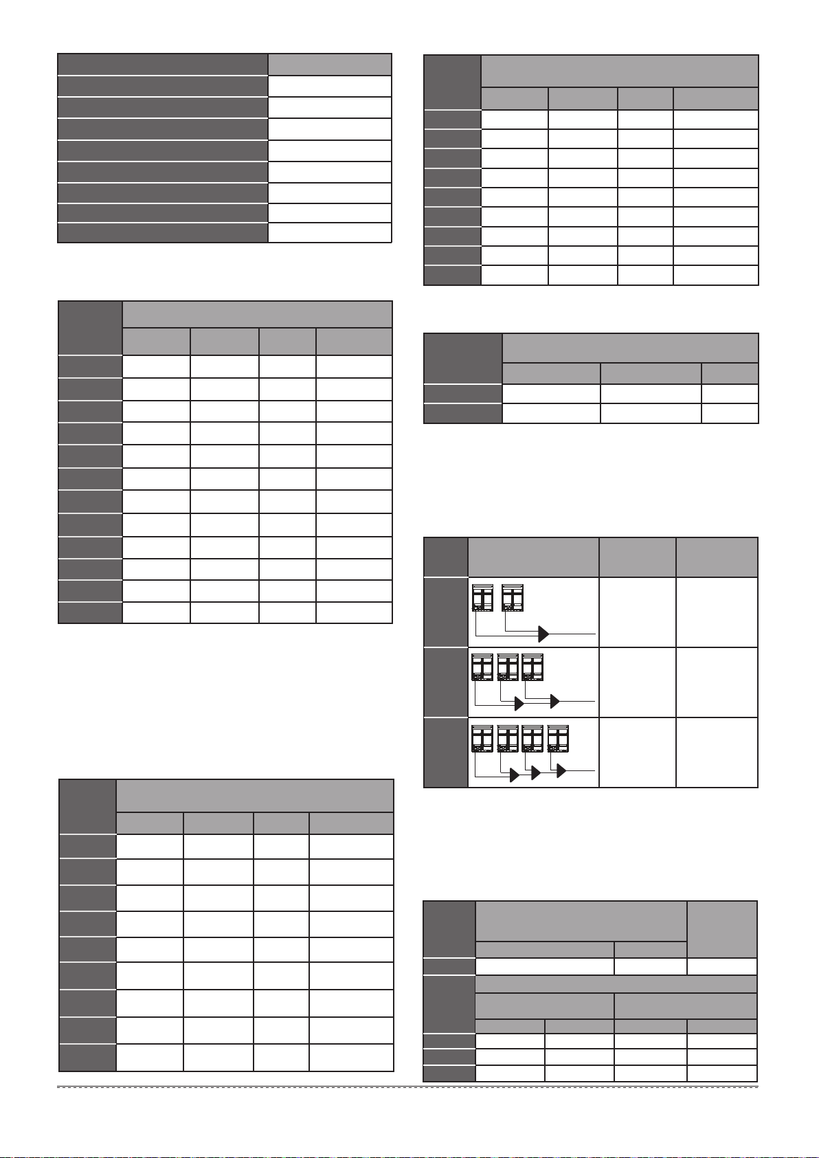
5.4 Size of joint pipes for outdoor unit
Model
gas side
Low-pressure
gas side
High-pressure
Liquid side
Φ22.2 Φ19.05
Φ25.4 Φ19.05
Φ28.6 Φ22.2
Φ31.8 Φ28.6
Φ28.6
Φ28.6
Φ34.9
Φ34.9
Φ12.7
Φ12.7
Φ15.88
Φ15.88
Φ15.88
Φ19.05
When the equivalent length of all liquid
pipes < 90m, the size of main pipe(mm)
8HP
10HP
14~16HP
18~22HP
24HP
26~32HP
Size of joint pipes for R410A outdoor unitTable.5-4
SP-FQG-N03S
SP-FQG-N04S
Φ25.4 Φ19.05 Φ12.7
12HP SP-FQG-N04S
SP-FQG-N05S
SP-FQG-N06S
SP-FQG-N06S
SP-FQG-N06S
Φ34.9Φ41.3 Φ19.05
34~48HP SP-FQG-N07S
Φ38.1Φ44.5 Φ22.2
50~64HP SP-FQG-N08S
Model
Liquid side
Φ25.4
Φ25.4
Φ31.8
Φ31.8
Φ34.9
Φ38.1
Φ19.05
Φ19.05
Φ22.2
Φ28.6
Φ28.6
Φ28.6
Φ12.7
Φ12.7
Φ15.88
Φ19.05
Φ19.05
Φ22.2
When the equivalent length of all liquid
pipes ≥ 90m, the size of main pipe(mm)
8HP
10HP
14~16HP
18~22HP
24HP
26~32HP
Size of joint pipes for R410A outdoor unitTable.5-5
SP-FQG-N04S
SP-FQG-N04S
Φ28.6 Φ19.05 Φ15.8812HP SP-FQG-N05S
SP-FQG-N06S
SP-FQG-N06S
SP-FQG-N09S
SP-FQG-N06S
Φ41.3 Φ34.9 Φ22.234~48HP SP-FQG-N09S
Φ44.5 Φ38.1 Φ25.450~64HP SP-FQG-N10S
Base on the following tables, select the diameters of outdoor
unit main connective pipe. In case of the main accessory pipe
of indoor unit larger than outdoor unit main connective pipe,
take the large one for the selection.
The 1st branching
pipe for indoor unit
The 1st branching
pipe for indoor unit
gas side
Low-pressure
gas side
High-pressure
e.x.1: Refer to Fig.5-3 , the capacity of downstream units to L3 is
71×2+28=170, i.e. low pressure gas pipe for L3 is Φ22.2,high pressure gas
pipe is Φ19.05,high pressure liquid pipe is Φ12.7.
5.3 Size of joint pipes for indoor unit
5.5 Branch pipes for outdoor unit
gas side
Low-pressure
gas side
High-pressure
Capacity of
indoor unit
A(×100W)
Indoor unit main pipe(mm)
Liquid side
Φ15.88
Φ19.05
Φ22.2
Φ25.4
Φ28.6
Φ12.7
Φ15.88
Φ19.05
Φ22.2
Φ22.2
Φ9.52
Φ9.52
Φ12.7
Φ12.7
Φ12.7
65≤A<90
A<65
90≤A<170
170≤A<280
280≤A<335
335≤A<400
Size of joint pipes for R410A indoor unitTable.5-3
Table.5-6
SP-FQG-N02S
SP-FQG-N02S
Φ12.7 Φ9.52
Φ9.52 SP-FQG-N01S
SP-FQG-N04S
SP-FQG-N03S
SP-FQG-N04S
Φ28.6
Φ31.8
Φ22.2
Φ25.4
Φ15.88
Φ15.88
400≤A<532
532≤A<680
680≤A<730
SP-FQG-N05S
SP-FQG-N06S
Φ34.9 Φ28.6
Φ15.88 SP-FQG-N06S
Φ34.9
Φ41.3
Φ28.6
Φ34.9
Φ19.05
Φ19.05
730≤A<960
960≤A<1350
A≥1350
SP-FQG-N06S
SP-FQG-N07S
Φ44.5 Φ38.1
Φ22.2 SP-FQG-N08S
8~12HP
Model
Φ22.2 Φ19.05 Φ15.88
14~16HP Φ28.6 Φ22.2 Φ15.88
Low-pressure gas side High-pressure gas side
Liquid side
5.7 Example
Available
branching pipe Outdoor unit pipe connective
opening dimension(mm)
Take (10+12+16) HP that composed by three modules as an
example to clarify the pipe selection.
Take Fig.5-3 as an example. Provided that the equivalent
length of all pipes in this system is larger than 90m, the branch
pipe’s length is less than 10m.
1)
2)
5.6 Multi connecting pipe assembly and pipe
diameter for outdoor unit
Table.5-7 Outdoor unit multi connecting pipe assembly (Illustration)
Base on Table 5-7 select the multi connecting pipe assembly of
outdoor unit. Before installation, please read the Outdoor Unit
Branching Pipe Installation Manual carefully.
Illustration
Parallel connect
with the branch
pipes
Outdoor unit
connective
pipe diameter
g1,g2:
8~12HP:
Φ22.2/Φ19.05/Φ12.7
14、16HP:
Φ28.6/Φ22.2/Φ15.88
g1,g2,g3:
8~12HP:
Φ22.2/Φ19.05/Φ12.7
14、16HP:
Φ28.6/Φ22.2/Φ15.88
G1:Φ34.9/Φ28.6/Φ19.05
g1,g2,g3,g4:
8~12HP:
Φ22.2/Φ19.05/Φ12.7
14,16HP:
Φ28.6/Φ22.2/Φ15.88
G1:
Φ34.9/Φ28.6/Φ19.05
G2:Φ41.3/Φ34.9/Φ22.2
L+M:
SP-FQG-W3C
L+M+N:
SP-FQG-W4C
L:
SP-FQG-W2C
Outdoor
unit Qty.
2 units
3 units
4 units
LM
g1g2
G1
g3
Main pipe
LMN
g1g2
G1 G2
g3g4
Main pipe
Main pipe
L
g1g2
Table.5-2
L2~L11
L1
a, b,c...t
g1, g2, g3, G1
CS1,...CS6
A, B, C, D, E
L, M
Pipe name Code (As per the Fig. 5-3)
Main pipe
Indoor unit main pipe
Indoor unit aux. pipe
Indoor unit main pipe branching pipe assembly
Indoor unit aux.pipe branching pipe assembly
Outdoor unit branching pipe assembly
Outdoor unit connective pipe
CS equipment
Ⅰ,Ⅱ,Ⅲ
Table.5-8
Indoor unit aux. pipe
(between branch joint and branch joint/CS)
(
mm
)
Indoor unit aux. pipe(between indoor unit and branch joint/CS)
(
mm
)
Liquid side
The branch
pipe assembly
of indoor unit
aux. pipe
Gas side
Capacity of
indoor unit
A(×100W)
Capacity of
indoor unit
A(×100W)
A<160 Φ15.88 Φ9.52 SP-FQG-N02S
22≤A≤28
36≤A≤56
Liquid side Liquid sideGas side Gas side
Φ9.52 Φ6.35
Φ12.7 Φ6.35 Φ15.88 Φ9.52
71≤A≤160 Φ15.88 Φ9.52 Φ19.05 Φ12.7
Φ12.7 Φ9.52
When branching
pipe’s length ≤10m
When branching
pipe’s length>10m
Branching pipe at the inside of the unit.
There are b,c,d,e,f,g,h,i,j,k,m,o,p,q,r,s,t branching pipes at the
inside of the unit, the branching pipe diameter should be select
as per Table 5-8.
Main pipe and aux.pipe at the inside of the unit (Refer to Table
5-3 and Table 5-8)
The aux. pipe a with N1, N2 downstream indoor units that total
capacity is 71×2=142, the pipe a diameter is Φ15.88/Φ9.52, thus
select SP-FQG-N02S for the branching pipe Ⅰ.
The main pipe L3 with N1, N2, N3 downstream indoor units that
total capacity is 71×2+28=170, the pipe L3 diameter is Φ22.2/
Φ19.05/Φ12.7, thus select CS02 for CS1.
The main pipe L5 with N4, N5 downstream indoor units that total
capacity is 56+28=84, the pipe L5 diameter is Φ15.88/Φ12.7/
Φ9.52, thus select CS02 for CS2.
The main pipe L6 with N6, N7 downstream indoor units that total
capacity is 71×2=142, the pipe L6 diameter is Φ19.05/Φ15.88/
Φ9.52, thus select CS02 for CS3.
The main pipe L4 with N4~N7 downstream indoor units that total
capacity is 71×2+56+28=226, the pipe L4 diameter is Φ22.2/
Φ19.05/Φ12.7, thus select SP-FQG-N03S for the branching
pipe C.
The main pipe L2 with N1~N7 downstream indoor units that total
capacity is 71×4+56+28×2=396, the pipe L2 diameter isΦ28.6/
Φ22.2/Φ12.7, thus select SP-FQG-N04S for the branching pipe
B.
The aux. pipe n with N12, N13 downstream indoor units that total
capacity is 56×2=112, the pipe n diameter is Φ15.88/Φ9.52, thus
select SP-FQG-N02S for the branching pipe Ⅲ.
The aux. pipe l with N11, N12, N13 downstream indoor units that
total capacity is 56×2+28=140, the pipe l diameter is Φ15.88/
Φ9.52, thus select SP-FQG-N02S for the branching pipe Ⅱ.
The main pipe L10 with N8, N9 downstream indoor units that
total capacity is 71×2=142, the pipe L10 diameter is Φ19.05/
Φ15.88/Φ9.52, thus select CS02 for CS4.
The main pipe L11 with N10~N13 downstream indoor units that
total capacity is 56×2+140+28=280, the pipe L11 diameter is
Φ25.4/Φ22.2/Φ12.7, thus select CS02 for CS5.
The main pipe L9 with N8~N13 downstream indoor units that
total capacity is 140+71×2+56×2+28=422, the pipe L9 diameter
is Φ28.6/Φ22.2/Φ15.88, thus select SP-FQG-N05S for the
branching pipe E.
The main pipe L8 with N14~N17 downstream indoor units that
total capacity is 28×2+56+140=252, the pipe L8 diameter is
Φ22.2/Φ19.05/Φ12.7, thus select CS04 for CS6.
The main pipe L7 with N8~N17 downstream indoor units that
total capacity is (140+71)×2+(28+56)×3=674, the pipe L7
diameter is Φ31.8/Φ25.4/Φ15.88, thus select SP-FQG-N06S for
the branching pipe D.
Main pipe (Refer to Table 5-3, Table 5-5):
Main pipe L1 in the Fig.5-3, which upstream outdoor units total
capacity is 16+12+10=38, base on table 5-5, the low-pressure
gas/high-pressure gas/liquid pipe diameter are Φ41.3/Φ34.9/
Φ22.2, total capacity of the downstream indoor unit(N1~N17) is
28×5+56×4+71×6+140×2=1070, base on table 5-3, the
low-pressure gas/high-pressure gas/liquid pipe diameter are
Φ41.3/Φ34.9/Φ19.05, take the large one for your selection, final
confirm the main pipe diameter is: low-pressure gas/ high-pres-
sure gas/ liquid pipe Φ41.3/Φ34.9/Φ22.2, thus select
SP-FQG-N09S for the branching pipe A.
Parallel connect the outdoor units
The outdoor unit linked by Pipe g1 is 10HP, parallel connects
with outdoor unit. the connective pipe diameter to be selected
according to its connector size is Φ22.2/Φ19.05/Φ12.7;
The outdoor unit linked by Pipe g2 is 12HP, parallel connects
with outdoor unit. the connective pipe diameter to be selected
according to its connector size is Φ22.2/Φ19.05/Φ12.7;
The outdoor unit linked by Pipe g3 is 16HP, parallel connects
with outdoor unit. the connective pipe diameter to be selected
according to its connector size is Φ28.6/Φ22.2/Φ15.88.
G1 is the upstream of the two parallel connected outdoor units,
refer to Table 5-7 select the two parallel connected outdoor unit,
the pipe diameter is Φ34.9/Φ28.6/Φ19.05.
Parallel connect the three outdoor units, refer to Table 5-7 should
select SP-FQG-W3C for outdoor unit connective pipes (L+M).
A.
B.
1)
2)
3)
4)
5)
6)
7)
8)
9)
10)
11)
12)
13)
C.
D.
1)
2)
3)
Fig.5-4
11
Installation manual
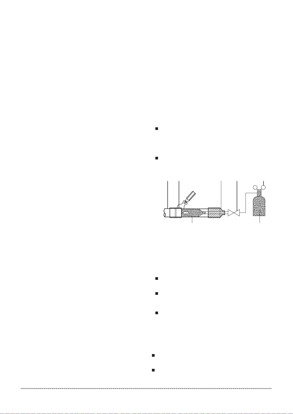
5.8 Caution for brazing
5.9 Remove dirt or water in the piping
Make sure there is no any dirt or water before connecting
the piping to the outdoor units.
Wash the piping with high pressure nitrogen, never use
refrigerant of the outdoor unit.
Make sure to blow through with nitrogen when brazing.
Blowing through with nitrogen prevents the creation of large
quantities of oxidized film on the side of the pipe. An oxidized
film adversely affects valves and compressors in the
refrigerating system and prevents proper operation.
The nitrogen pressure should be set to 0.02Mpa(i.e.,just
enough so it can be felt on the skin)with a pressure-reducing
valve.
Do not use anti-oxidants when brazing the pipe joints.
Residue can clog pipes and break equipment.
Do not use flux when brazing copper-to-copper refrigerant
piping. Use phosphor copper brazing filler alloy(BCuP) which
does not require flux.
Flux has an extremely harmful influence on refrigerant pipe
systems. For instance,if chlorine based flux is used, it will
cause pipe corrosion or, in particular, if the flux contains
fluorine, it will deteriorate the refrigerant oil.
1 Refrigerant pipe
2 Part to be brazed
3 Taping
4 Hands valve
5 Pressure-reducing valve
6 Nitrogen
1 2 3 4 5
6 6
CAUTION
CAUTION
5.12 Refrigerant amount to be added
Calculate the added refrigerant according to the diameter
and the length of the liquid side pipe of the outdoor/indoor
unit connection. The refrigerant is R410A.
Fill the additional quantity of calculated refrigerant from the
low-pressure pipe and liquid pipe.
The system is back to electricity after power outages, and
then quit from the vacuum state.
Pipe size on
liquid side(mm)refrigerant to be
Added per meter(kg)
Φ6.35
Φ9.52
Φ12.7
Φ15.88
Φ19.05
Φ22.2
Φ25.4
Φ28.6
0.023
0.060
0.120
0.180
0.270
0.380
0.520
0.680
Table.5-9
Don’t mix up the different refrigerants or abuse the tools and
measurements which directly contact with refrigerants.
Don’t adopt refrigerant gas for air vacuuming.
If vacuum level could not get to -0.1MPa, please check whether
resulted by leakage and confirm the leakage site. If no leakage,
please operate the vacuum pump again 1 or 2 hours.
During the vacuum operation, in order to keep related valves open
and discharge air inside the system, please power on all outdoor
units, CS mode switch boxes and indoor units.
After finish vacuum, please repower on the system and system
will exit the vacuum mode automatically.
Pressurized nitrogen(3.9MPa;40kgf/cm2)is used for
airtightness test.
It is not allow to bring pressure on the float valve directly.
(See Fig. 5-4)
It is not allow to use oxygen, combustible gas or toxic gas
to conduct the airtightness test.
When welding, please use wet cloth insulating the low
pressure valve for protection.
For avoid the equipment be damaged, the pressure
maintained time should not last too long.
Fig.5-7
●
●
●
●
●
Note:
1. Assume equivalent pipe length of the branching pipe header to be 0.5m.
2. The refrigerant amount to be added of CS02 is 0.3kg/per, of CS04/CS06
is 0.5kg/per.
12
Installation manual
5.10 Gas tight test
Charge 40kgf/cm2 nitrogen gas from the pistion of high-pressure
gas side valve from the meter connector. Pressure inside should
be maintained at there no less than 24 hours.
Fig.5-5
Indoor unit
Outdoor unit
CS
Nitrogen
Nitrogen
Nitrogen High-pressure gas pipe
Low-pressure gas pipe
Liquid pipe
Fig.5-6
Use the vacuum pump which vacuum level lower than
-0.1MPa and the air discharge capacity above 40L/min.
The outdoor unit is not necessary to vacuum, don’t open the
outdoor unit gas and liquid pipe shut-off valves.
Make sure the vacuum pump could result as -0.1MPa or
below after 2 hours or above operation. If the pump operated
3 hours or above could not achieve to -0.1MPa or below,
please check whether water mix or gas leak inside of the
pipe.
Pressure gauge with the switch is installed between vacuum
pump and system pipes.
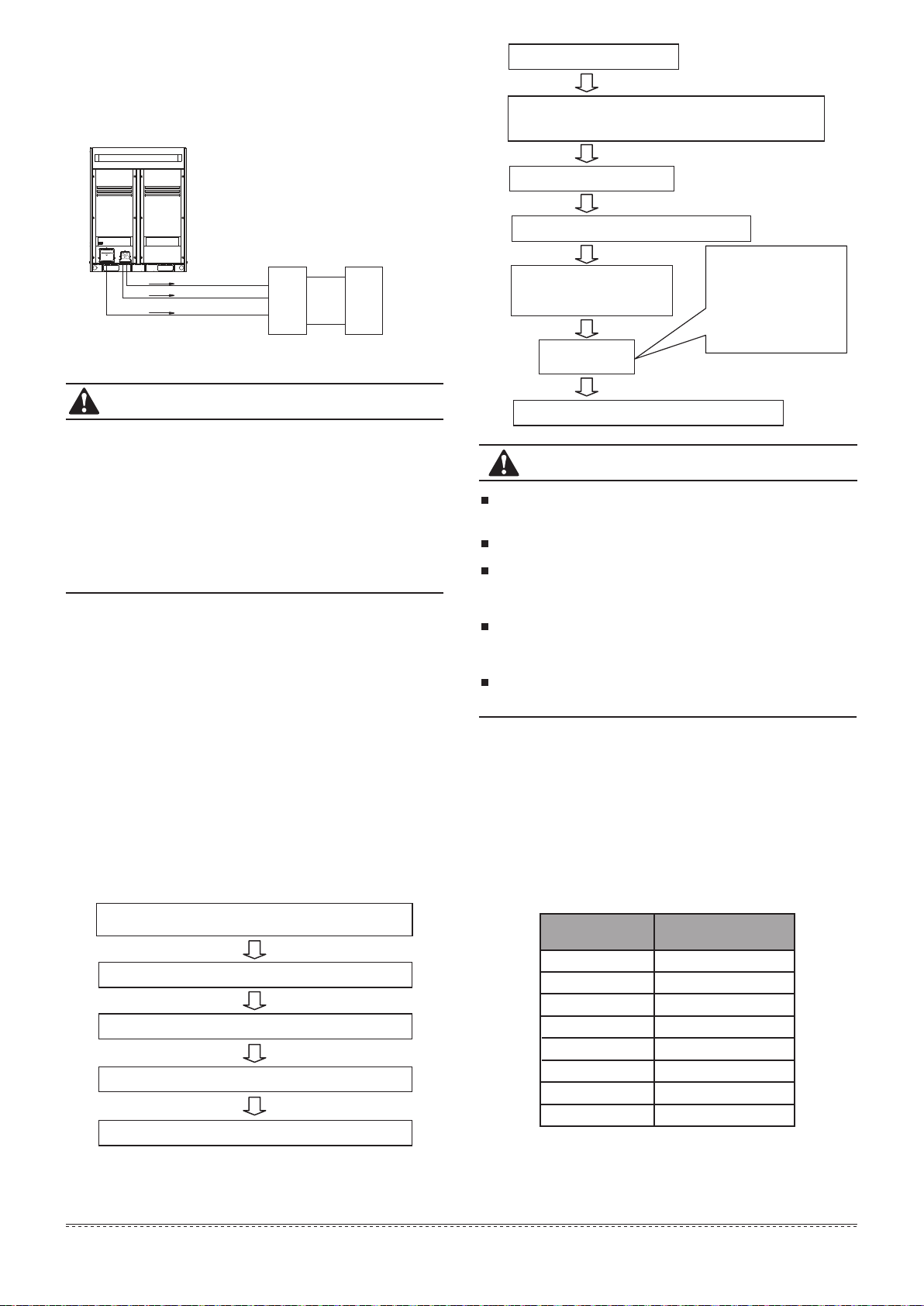
5.11 Vacuum with vacuum pump
1)
2)
3)
4)
1)
2)
3)
Respectively connect the vacuum pump in the gas
balance valve and oil balance valve
Perform the pump (last for 10 minutes or above)
Close the pressure gauge and vacuum pump in turn
Open the gas balance valve and oil balance valve of the outdoor unit
Remove the pressure gauge and vacuum pump
After the system power outages.
After the system is powered on, long press SW14 check
button for 5 senonds until displaying 000. And then press
the key of forced cooling,UA is displayed.
Into the vacuum state
Connect with vacuum pump
Perform the pump (last for 2 hrs or above)
When get the vacuum level
-0.1MPa, the pump should
keep running for 20-60 mins
Shut down the
vaccun pump
Place the vaccum state unused (1 hrs or above)
1. Close-off the valve of
vacuum meter.
2. Cut off the connection
between pressure meter
and vacuum pump.
3. Close the vacuum
pump.

5.13 The Installation key points of connective
pipes between outdoor units
Connect the pipes between outdoor units, the pipes should
place horizontally (Fig.5-8,Fig.5-9), it is not allow the concave
at junction site(Refer to Fig.5-10).
All connective pipes between the outdoor units are not
allowed to over than the height of every outlets of the
pipes(Refer to Fig.5-11).
1)
2)
13
Installation manual
Fig.5-12
Fig.5-13
Fig.5-14
The branching pipe must be installed horizontally, error angle
of it should not large than 10°. Otherwise, malfunction will be
caused.
CorrectWrong
U-shaped branching pipe
Horizontal surface
A direction view
For avoid oil accumulate at the outdoor unit, please install the
branching pipes properly.
3)
4)
Fig.5-8
Correct way
Correct way
× Wrong way
Fig.5-9
Fig.5-10
Fig.5-11
× Wrong way
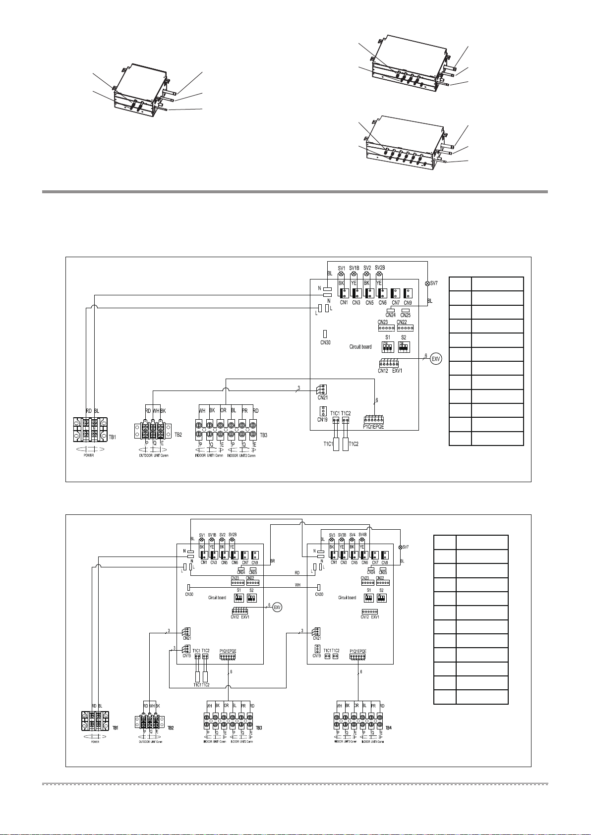
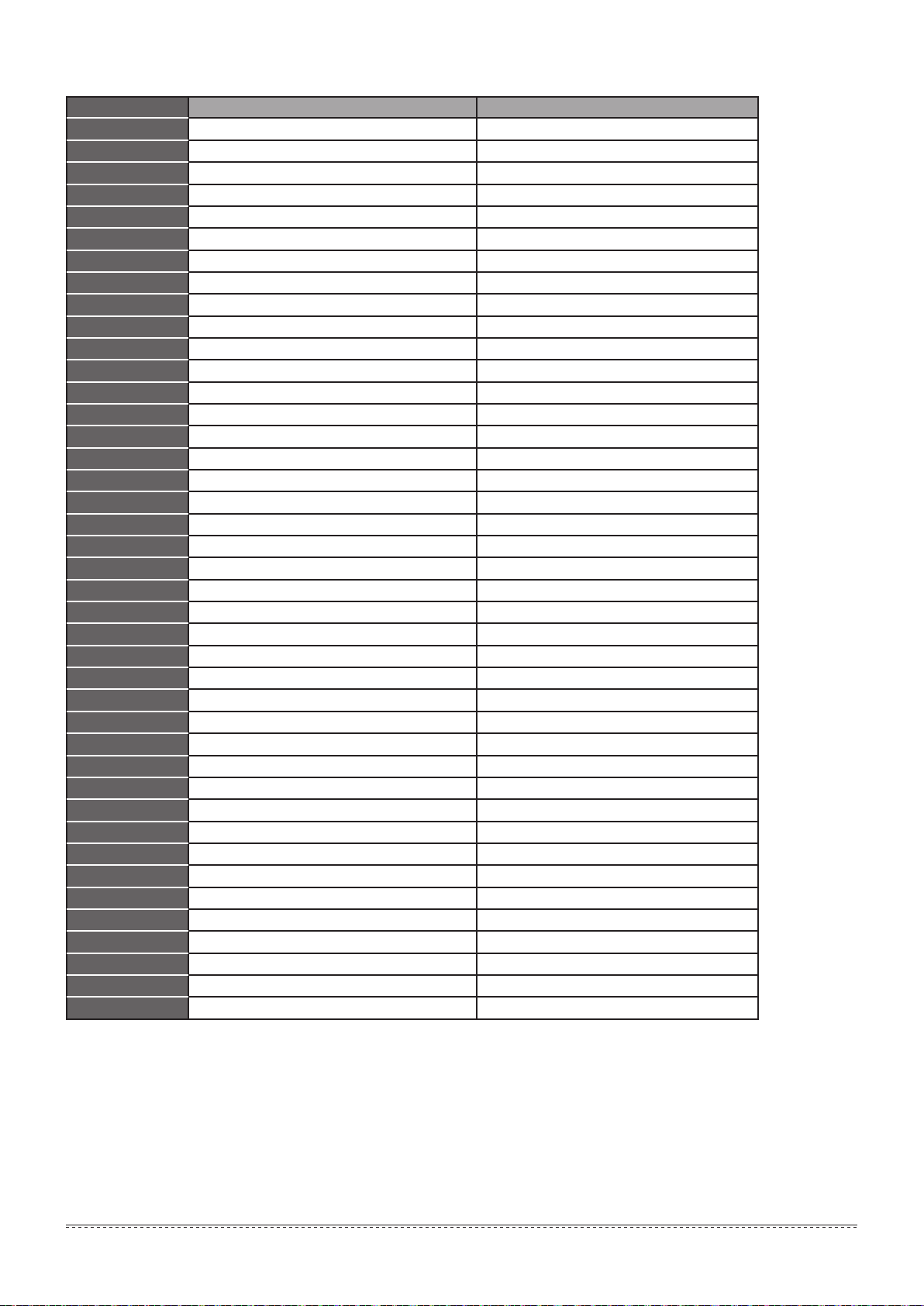
6. CONNECTING PIPE OF CS
7. CS WIRING NAMEPLATE
14
Installation manual
Fig.6-3
Fig.6-2
Fig.6-1
Fig.7-1
Fig.7-2
7.1 the nameplate of CS02
7.2 the nameplate of CS04
Liquid pipe(Φ9.52)
Gas pipe(Φ15.88)
Liquid pipe(Φ15.88)
High-pressure gas pipe(Φ22)
Low-pressure gas pipe(Φ32)
CS06
Liquid pipe(Φ9.52)
Gas pipe(Φ15.88)
Liquid pipe(Φ15.88)
High-pressure gas pipe(Φ22)
Low-pressure gas pipe(Φ32)
CS04
Liquid pipe(Φ9.52)
Gas pipe(Φ15.88)
Liquid pipe(Φ12.7)
High-pressure gas pipe(Φ19.05)
Low-pressure gas pipe(Φ25.4)
CS02
Solenoid valve coil
RD RED
BL BLUE
BK BLACK
YE YELLOW
WH WHITE
OR ORANGE
PR PURPLE
EXV
SV
Electronic
expansion valve
Supercooled pipe
intlet temperature
TB Terminal block
T1C1
TIC2
Supercooled pipe
outlet temperature
Solenoid valve coil
RD RED
BL BLUE
BK BLACK
YE YELLOW
WH WHITE
OR ORANGE
PR PURPLE
EXV
SV
Electronic
expansion valve
Supercooled pipe
intlet temperature
TB Terminal block
T1C1
TIC2
Supercooled pipe
outlet temperature
NOTE: Units need to use a dedicated power supply, avoid sharing the same circuit with other appliances. In connection
with the dedicated power supply, be sure to use the specified cross-section of the power cord, and match the
corresponding specifications of the circuit breakers, use the specified capacity fuse.

380-415V 3N~50Hz
Fig.8-1
8.1 Terminal base function
Fig.8-2
8. ELECTRIC WIRING
15
Installation manual
Fig.7-3
single group pipe means a piece of liquid pipe and a piece of gas
pipe.
If the indoor units do not have auto mode function, then each
group pipe of CS only can be connected 4 indoor units at most
for one time; if the indoor units have auto mode function, then
each group pipe of CS only can be connected 1 indoor unit at
most for one time.
Indoor units in the same group pipe of CS can not operate
cooling and heating at the same time, or operate heating and air
supplying at the same time, otherwise it will be modes conflict.
Please install the CS at the places where do not have highly
request for noise, such as the corridor or washroom and so on.
The CS must be installed horizontally.
There shall be at least 1m distance between the CS and the
branch pipes while doing installation.
There will be 30 seconds auto-checking function after the indoor
and outdoor units have been started up.
The indoor unit must use the remote controller for setting
address, the addresses of the indoor units connected with the
CS in the same system can not be the same (no matter whether
connected with the same CS).
7.3 The nameplate of CS06
Table.7-1
CS02 CS04 CS06
40m
4
16kW
28kW 45kW
Model of CS
Maximum
capacity of single
group pipe
Maximum indoor
units quantity of
single group pipe
Maximum
capacity of CS
Downstream of
the largest length
NOTE
Outdoor units
communication
Digital electricity
meter
Indoor units
centralized
controls
CS
communication
Outdoor units
centralized
monitoring
NOTE: Units need to use a dedicated power supply, avoid sharing the same circuit with other appliances. In connection
with the dedicated power supply, be sure to use the specified cross-section of the power cord, and match the
corresponding specifications of the circuit breakers, use the specified capacity fuse.
Solenoid valve coil
RD RED
BL BLUE
BK BLACK
YE YELLOW
WH WHITE
OR ORANGE
PR PURPLE
EXV
SV
Electronic
expansion valve
Supercooled pipe
intlet temperature
TB Terminal block
T1C1
TIC2
Supercooled pipe
outlet temperature
8.2 Spot inspection for outdoor unit
Table.8-1
Displays when system is running
Displays when system standby
0,1,2,3
0,1,2,3
0,1,2,3
8,10,12,14,16
0,1,2,3
Inverter compressor frequency
Number of indoor units
1
2
3
4
5
6
7
8
9
10
11
12
13
14
15
16
17
18
19
20
21
22
23
24
25
26
27
28
29
30
31
32
33
34
35
36
37
38
39
Reference valuesDisplay
Outdoor unit itself capacity
Outdoor unit address
Modular outdoor unit qty.
Available for main unit
Available for main unit
Available for main unit
0,2,3,4,5,6
No.
Total capacity of outdoor unit
Night noise control mode
Static pressure mode
Cooling capacity
Heating capacity Auxiliary unit only display capacity of main mode
Auxiliary unit only display capacity of main mode
T4 ambient temp. revision of cooling capacity
T4 ambient temp. revision of heating capacity
Outdoor unit running mode
The outdoor unit actual operation capacity Capacity requirement
Capacity requirement
Speed of left fan
Speed of right fan
0, 1,······,14,15
0, 1,······,14,15
T2 average temp. Actual value
Actual value
T3-L
T3-R
Actual value
Actual value
Actual value
Actual value
Actual value+60
Actual value=Display value×8
Actual value=Display value×8
Actual value=Display value×0.1MPa
Actual value
Actual value
Mode priority
Actual value
Actual value
Actual value=Display value×40
T2B average temp.
T3 pipe temp. (Left heat exchanger pipe temp. )
T5 pipe temp. ( Right heat exchanger pipe temp. )
T4 ambient temp.
Discharge temp. of A/B inverter compressor
Top temp.of A/B inverter compressor
Discharge high-pressure corresponding to the saturation temp.
Opening degree of rihgt EXV
Opening degree of left EXV
Reserve
Reserve
High pressure
Software version
Last protection code or error code
Qty. of indoor units
Qty. of cooling indoor units
Qty. of heating indoor units
That can communicate with indoor units
AC voltage
Secondary current
No protection or fault display 00
State of the evaporator or condenser
Spot inspection finished
Secondary voltage
Current of A/B inverter compressor
The display contents as followings:
Normal display:
When standby, the high position displays the address of the outdoor unit,and the low position displays the Qty. of indoor units
that can communicate with outdoor unit.When it is operating,it will display the rotation frequency of the compressor.
Outdoor unit running mode:
0-Off; 2-Cooling; 3-Heating; 4-Forced cooling; 5-Mixed cooling; 6-Mixed Heating.
Fan speed:
0-stop; 1~15 speed increase sequentially, 15 is the max. fan speed.
State of the evaporator or condenser:
0-All condenser; 1-Left evaporator/right condenser; 2-All evaporator; 3-Left evaporator/close.
Night noise control mode:
0-Night noise control mode;1-silent mode;2-Most silent mode;3-No priority.
Static pressure mode:
0-static pressure is 0 Mpa;1-Low static pressure;2-Medium static pressrue;3-High static pressure.
16
Installation manual

8.3 Explanation of mainboard
17
Installation manual
Fig.8-3
Table.8-2
1
No.
2
3
4
5
6
7
8
9
10
11
12
13
14
15
16
17
18
19
20
21
22
23
24
25
26
27
28
29
30
Content
Functional port for phase sequence detection
F1,F2,POWER,HEATER outlet
Power output of mainboard transformer
Power supply input of mainboard and module transformers
Program download port 1
Drive ports of the electronic expansion valve 2
Interface for the exhaust sensor of No.2 frequency-variable
compressor
Interface for the exhaust sensor of No.1 frequency-variable
compressor
Input port for detection of the system low pressure
SV1,SV2,SV3,SV4 outlet
The left four-way valve and The right four-way valve
Drive ports of the electronic expansion valve 1
Power output of module board transformer
IPM module 15V power port
Module board communication port 2
Module board communication port 1
Communication port between outdoor units
Input port for detection of the system high pressure
Drive ports of the electronic expansion valve 3 and 4(Reserved)
SV5,SV6,4-WAY outlet
Port for detection of the outdoor ambient temperature and the
left condenser coil temperature (T3)
Port to detect the primary side current A converter and B
inverter compressors
Input port for signal of the system low-pressure detector switch
Input port for signal of the system high-pressure detector switch
Control port of the DC fan 2 (Right fan)
Control port of the DC fan 1 (Left fan and Single fan)
Interface for electric meter for online control and charging of
the outdoor unit
Port for indoor-outdoor unit communications and indoor unit
network wiring
The right condenser coil temperature (T5)
Reserved
Reserved
Program download port 2
31
32

18
Installation manual
1) 8~12HP
2) 14~16HP
8.4 Outdoor unit wiring connection diagram
Caution 1: E1,E2 electrolytic capacitors release electricity after power outage.
Caution 2: Mutual reactors must be connected through with power cord.
Caution 1: E1,E2 electrolytic capacitors release electricity after power outage.
Caution 2: Mutual reactors must be connected through with power cord.
Fig.8-4
Fig.8-5
E1 Electrolytic
Capacitor
E2 Electrolytic
Capacitor
XT1 Main Power
Terminal
XT2 Comm.
Terminal
DZ1 Triphase
Bridge
DZ2 Uniphase
Bridge
SV2 Bypass
Solenoid Valve
SV4 Oil Balance
Solenoid Valve
SV5 Defroist
Solenoid Valve
SV6 Flow valve
ST3 Main
4-way valve
POWER Start contactor
control
PTC PTC
ST1
ST2
CS Unit
4-way valve
4-way valve
Right
Left
Refrigerant
conversion
device
N
P
IPM
CN3
CN9
J1
1
U
V
W
2
CN2
5
3
FM BRD
MOTER
FB JOINT
TO MAIN
BRD
JOINT
P3
P4
P2 P1
CN1 CN2
P6
P5
L
N
L1
N1
CN11
A
INPUT
LOAD
L1 L2 L3 N
N
P
IPM
CN3
CN9
J1
1
U
V
W
2
CN2
MOTER
FB
JOINT
TO MAIN
BRD
JOINT
BCN
A1 B1 C1 N1
HEATER
POWER
F1
F2
4-WAY
SV6
SV5
SV4
SV3
SV2SV1
SV7
SV8
N
Filter BRD
AC
AC
Reactor
SV2 SV4 SV5 SV6 ST3
Fan
Motor
5
3
RD YE BL BK
YE
BK
RD YE BL BK
OR
OR
RD
RD
BK
BK
BL
YE
RD
RD
RD
RD
RD
BR
BL
BK
RD
BR
BL
4
BK
RD
3-phase power input
FM BRD
FM PW
BRD
RD
BK
L1 L2 L3 N
CN1
E1
E2
XT1
DZ1
DZ2
HEAT
INV
HEAT
INV
PTC1 PTC2
Mutual
Inductor
2
BK
ST1
IPM
Module
BRD
P
U
V
W
N
Inverter
Compressor
P1
N1
U
V
W
RD
YE
BL
BK
RD
CN7
CN5
LED1
LED2
LED3
CN4
CN18
CN14
CN21
CN2
CN1
CN20
CN19
CN17
CN28 CN30 CN26 CN25 CN27 CN28 CN13 CN34 CN6
CN24 CN22
CN23CN32
CN3
3-Phase power
Check
T2 TX4 TX3
IDU COMM
ODU
Centralized
controller &
Ammeter
Fan
Drive1#
Fan
Drive2#
HP LP
Hi.
Pressure
sensor
ODU
COMM.
Comm.
IPM B
T3
I A B
T4
1#
Transformer Input
SV8 SV7 SV1 SV2 SV3 SV4 SV5 SV6 4-WAY
F2 F1 POWER HEATER
2#
1
#
EXV
CHECK_A
Forced
refrigeration
ODU MAIN
CONTROL BRD
Condensing
temp
Environment
temp. Hi.
Pressure
sensor
A1
B1
C1
N1
Hi.
Prss
swicth.
Lo.Prss
swicth.
2#
±
15V
CN35 CN36
2
#
EXV
CHECK_B
System A System B
CN33CN12
Comm.
IPM A
1 2 3
ON DP
1 2 3
ON DP
1 2 3
ON DP
1 2 3
ON DP
1 2
ON
0
1
2345
6
7
8
9
A
B
C
D
E
F
SW4SW10 SW5 SW9SW8
SW12
1 2
ON
1 2
ON
0
1
2345
6
7
8
9
A
B
C
D
E
F
0
1
2345
6
7
8
9
A
B
C
D
E
F
SW7 SW15 SW6 SW11
1 2
1 2
ON
SW13
CN15
3
T1
4
T2
INV
A
EXHAUST TEMP
3
T1
4
T2
CN8
CN16
Condensing
temp(T5)
Current
1#
Transformer Output
CN2'
TRANS1
6
5
34
5
LCD
DISPLAY
N N N N N N N N NNNN
1 2
ON
SW12
K1K2 E D A E X Y E P QE H1H2 E
ODU Monitor
Digital Ammeter
IDU Centralized
Controller
CS Units
COMM.
ODU COMM.
XT2
1#EVX
RC
BOARD
BK
RD
ST2
Top Pip
Fan
Motor
Right
Left
5
BK
Reactor
OR
OR
OR
BK
OR
RD
RD
RD
RD
RD
RD
RD
RD
RD
BK
BK
BK
BK
RD
RD
YE
BL
E2
E1
RD E4
E3
RD
RD
COMP
(INV-B)
COMP
ST2 ST3
BL
BL
YE
YE
RD
RD
5
Top Pip
Top Pip
Right
Left
ST1
CN35 CN36
2
#
EXV
CHECK_B
System A System B
CN33CN12
Comm.
IPM A
1 2 3
ON DP
1 2 3
ON DP
1 2 3
ON DP
1 2 3
ON DP
1 2
ON
0
1
2345
6
7
8
9
A
B
C
D
E
F
SW4SW10 SW5 SW9SW8
SW12
1 2
ON
1 2
ON
0
1
2345
6
7
8
9
A
B
C
D
E
F
0
1
2345
6
7
8
9
A
B
C
D
E
F
SW7 SW15 SW6 SW11
1 21 2
ON
SW13
CN15
3
T1
4
T2
INV
A
EXHAUST TEMP
3
T1
4
T2
INV
B
CN8
CN16
Lo.
Pressure
sensor
Condensing
temp(T5)
Current
1#
Transformer Output
CN2'
LCD
DISPLAY
HEATER
POWER
F1
F24-WAYSV6
SV5
SV4
SV3
SV2SV1
SV7
SV8
N
SV2 SV4 SV5 SV6
BK
N N N N N N N N NNNN
HEAT
INV A
HEAT
INV B
L1 L2 L3 N
RD YE BL BK
3
-phase power input
XT1
Reactor
OR
1# Mutual
Inductor 2# Mutual
Inductor
CN11
A
INPUT
LOAD
BCN
A1 B1 C1 N1
Filter BRD B
RD YE BL BK
L1 L2 L3 N
CN11
A
INPUT
LOAD
BCN
A1 B1 C1 N1
Filter BRD A
RD YE BL BK
L1 L2 L3 N
BL
WH
BK YE
DZ1-B
DZ1-A
PTC1
PTC2
BK
PTC1
PTC2
N
P
IPM
CN3
CN9
J1
1
U
V
W
2
CN2
MOTER
FB
JOINT
TO MAIN
BRD
JOINT
Fan
Motor
5
3
FM BRD
CN1
N
P
IPM
CN3
CN9
J1
1
U
V
W
2
CN2
5
3
FM BRD
Fan
Motor
MOTER
FB JOINT
TO MAIN
BRD
JOINT
FM PW
BRD
BK
BK
BK
YE
RD
BL
BL
BR
BR
BL
BR
RD YE BL RD YE BL
1 2
ON
SW12
K1K2 E D A E X Y E P QE H1H2 E
ODU Monitor
Digital Ammeter
IDU Centralized
Controller
CS Units
COMM.
ODU COMM.
XT2
TRANS1
6
5
3
4
5
P3
P4
P2 P1
P6
P5
L
N
L1
N1
AC
AC
DZ2
2
4
1#EXV
2#EXV
A IPM
Module
BRD
P
U
V
W
N
P1
N1
U
V
W
RD
YE
BL
BK
RD
BK
(INV-A)
B IPM
Module
BRD
P
U
V
W
N
P1
N1
U
V
W
RD
YE
BL
BK
RD
CN7
CN5
LED1
LED2
LED3
CN4
CN18
CN14
CN21
CN2
CN1
CN20
CN19
CN17
CN28 CN30 CN26 CN25 CN27 CN28 CN13 CN34 CN6
CN24 CN22
CN23 CN32
CN3
3-Phase power
Check
T2 TX4 TX3
IDU COMM ODU
Centralized
controller &
Ammeter
Fan
Drive1#
Fan
Drive2#
HP LP Hi.
Pressure
sensor
ODU
COMM.
Comm.
IPM B
T3
I A B
T4
1#
Transformer Input
SV8 SV7 SV1 SV2 SV3 SV4 SV5 SV6 4-WAY
F2 F1 POWER HEATER
2#
1
#
EXV
CHECK_A
Forced
refrigeration
ODU MAIN
CONTROL BRD
Condensing
temp
Environment
temp. Hi.
Pressure
sensor
A1
B1
C1
N1
Hi.
Prss
swicth.
Lo.Prss
swicth.
2#
±
15V
Electrolytic
Capacitor
Electrolytic
Capacitor
XT1
Main Power
Terminal
XT2
Comm.
Terminal
DZ1
Triphase
Bridge
DZ2
Uniphase
Bridge
SV2
Bypass
Solenoid Valve
SV4
Oil Balance
Solenoid Valve
SV5
Defroist
Solenoid Valve
SV6
Flow valve
ST3
Main
4-way valve
POWER
Start contactor
control
PTC PTC
3-phase
relay
KZ
E1/E2
E3/E4
ST1
ST2
4-way valve
4-way valve
Right
Left
CS Units
Refrigerant
conversion
device
Table of contents
Other Chigo Inverter manuals
 User manual")


Popular Inverter manuals by other brands

Huawei
Huawei 01075345 user manual

MSW
MSW MSW-CPI-380MS user manual

Latronics
Latronics PV Edge Grid Connect instruction manual

Giandel
Giandel PS-300C user manual

FSP Technology
FSP Technology LightUp L8000 user manual

Rayleigh Instruments
Rayleigh Instruments RI-ENERGYFLOW-MODULAR Series Quick start installation guide


