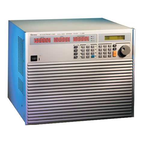
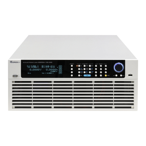
Chroma 63200 Series User manual

High Power DC Electronic Load
63200 Series
Soft Panel User’s Manual


High Power DC Electronic Load
63200 Series
Soft Panel
User’s Manual
Version 1.1
August 2012

Legal Notices
The information in this document is subject to change without notice.
Chroma ATE INC. makes no warranty of any kind with regard to this manual, including, but
not limited to, the implied warranties of merchantability and fitness for a particular purpose.
Chroma ATE INC. shall not be held liable for errors contained herein or direct, indirect,
special, incidental or consequential damages in connection with the furnishing, performance,
or use of this material.
CHROMA ATE INC.
66 Hwaya 1st Rd., Kueishan Hwaya Technology Park, Taoyuan County 33383, Taiwan
Copyright Notices. Copyright 2006 Chroma ATE INC., all rights reserved. Reproduction,
adaptation, or translation of this document without prior written permission is prohibited,
except as allowed under the copyright laws.
Disclaimer and Intellectual Property Rights Statements
Chroma ATE Inc. (“Chroma”) provides you the deployment license disc, including National
Instruments legally authorized software (“NI-VISA”); please note that any Copyrights,
Trademarks, Know-How or other Intellectual Property Rights of NI-VISAare the property of
National Instruments. Neither party shall copy, distribute, modify, resale or infringe any of
National Instruments Intellectual Property Rights except receipt of the express and prior
written permission of National Instruments. Any violations of National Instruments Intellectual
Property Rights will be at your sole risk, Chroma bear no legal responsibility and will not be
liable to you for any violations arising out of this statement. If you would like to obtain the
license legally or receive any information of violation of this statement, please contact us or
National Instruments.
ii

iii
Warranty
All Chroma instruments are warranted against defects in material and workmanship for a
period of one year after date of shipment. Chroma agrees to repair or replace any assembly
or component found to be defective, under normal use during this period. Chroma's
obligation under this warranty is limited solely to repairing any such instrument, which in
Chroma's sole opinion proves to be defective within the scope of the warranty when returned
to the factory or to an authorized service center. Transportation to the factory or service
center is to be prepaid by purchaser. Shipment should not be made without prior
authorization by Chroma.
This warranty does not apply to any products repaired or altered by persons not authorized
by Chroma, or not in accordance with instructions furnished by Chroma. If the instrument is
defective as a result of misuse, improper repair, or abnormal conditions or operations, repairs
will be billed at cost.
Chroma assumes no responsibility for its product being used in a hazardous or dangerous
manner either alone or in conjunction with other equipment. High voltage used in some
instruments may be dangerous if misused. Special disclaimers apply to these instruments.
Chroma assumes no liability for secondary charges or consequential damages and in any
event, Chroma's liability for breach of warranty under any contract or otherwise, shall not
exceed the purchase price of the specific instrument shipped and against which a claim is
made.
Any recommendations made by Chroma for use of its products are based upon tests
believed to be reliable, but Chroma makes no warranty of the results to be obtained. This
warranty is in lieu of all other warranties, expressed or implied, and no representative or
person is authorized to represent or assume for Chroma any liability in connection with the
sale of our products other than set forth herein.
CHROMA ATE INC.
66 Hwaya 1st Rd., Kueishan Hwaya Technology Park,
Taoyuan County 33383, Taiwan
Tel: 886-3-327-9999
Fax: 886-3-327-2886
e-mail: [email protected]
http://www.chromaate.com

Revision History
The following lists the additions, deletions and modifications in this manual at each revision.
Date Version Revised Sections
Sep. 2006 1.0 Complete this manual
Aug. 2012 1.1 Add “Disclaimer and Intellectual Property Rights Statements”
Modify the installation steps in “Installing Chroma 63200 Soft Panel”
and “Installing NI VISA Runtime” in the chapter of “Installation”.
iv

High Power DC Electronic Load 63200 Series Soft Panel User’s Manual
Table of Contents
1. System Structure...................................................................................................... 1-1
1.1 Introduction......................................................................................................... 1-1
1.2 Supported Hardware .......................................................................................... 1-1
1.3 Communication Interface.................................................................................... 1-1
1.4 Operation............................................................................................................ 1-1
1.5 Software and Hardware Requirements............................................................... 1-2
2. Installation................................................................................................................. 2-1
2.1 Files in CD.......................................................................................................... 2-1
2.2 Installing Chroma 63200 Soft Panel ................................................................... 2-1
2.3 Installing NI VISA Runtime.................................................................................. 2-6
2.4 Installing GPIB Interface Driver .......................................................................... 2-9
2.5 Uninstalling Chroma DC Load 63200 Soft Panel................................................ 2-9
3. Starting Chroma DC Load 63200 Soft Panel .......................................................... 3-1
3.1 Starting ............................................................................................................... 3-1
4. Setting Hardware...................................................................................................... 4-1
4.1 Using Demo Mode.............................................................................................. 4-2
4.2 Using Output Name and Active........................................................................... 4-2
4.3 Function Buttons................................................................................................. 4-3
4.4 Saving and Opening Parameter ......................................................................... 4-3
4.4.1 SAVE AS..................................................................................................... 4-3
4.4.2 OPEN.......................................................................................................... 4-4
4.5 Back.................................................................................................................... 4-4
4.6 Exit...................................................................................................................... 4-4
4.7 General............................................................................................................... 4-5
4.7.1 Von Point .................................................................................................... 4-5
4.7.2 Von Latch.................................................................................................... 4-5
4.7.3 CC V_range................................................................................................ 4-5
4.7.4 Current Limit............................................................................................... 4-5
4.7.5 CV Response.............................................................................................. 4-5
4.7.6 Meas. UUT/Load......................................................................................... 4-5
4.8 Static SPEC........................................................................................................ 4-6
4.9 Static Parameter Setting..................................................................................... 4-6
4.10 Reading Display ................................................................................................. 4-6
4.10.1 Graphic Reading Display............................................................................ 4-7
4.10.2 Numeric Display.......................................................................................... 4-7
4.10.3 Read Back Type Selection.......................................................................... 4-7
4.10.4 Refresh....................................................................................................... 4-7
5. Static Test.................................................................................................................. 5-1
5.1 Selecting Mode................................................................................................... 5-1
5.2 Setting Loading................................................................................................... 5-2
5.3 Reading Select................................................................................................... 5-2
5.4 Readback ........................................................................................................... 5-2
5.5 Setting Load On/Off............................................................................................ 5-3
5.6 Setting Short On/Off ........................................................................................... 5-3
5.7 Save to Firmware ............................................................................................... 5-3
5.8 Reading Display ................................................................................................. 5-3
5.9 SAVE AS, OPEN & BACK .................................................................................. 5-3
6. Dynamic Test ............................................................................................................ 6-1
6.1 Selecting Mode................................................................................................... 6-1
v

High Power DC Electronic Load 63200 Series Soft Panel User’s Manual
6.2 Setting Loading................................................................................................... 6-2
6.3 Setting Slew Rate............................................................................................... 6-2
6.4 Setting Frequency-Duty...................................................................................... 6-2
6.5 Setting Load On/Off............................................................................................ 6-3
6.6 Save to Firmware ............................................................................................... 6-3
6.7 Reading Display ................................................................................................. 6-3
6.8 SAVE AS, OPEN & BACK .................................................................................. 6-3
7. Program Test............................................................................................................. 7-1
7.1 Loading Simulation Waveform............................................................................ 7-1
7.2 Setting List Mode Parameter.............................................................................. 7-2
7.2.1 Setting List/Step.......................................................................................... 7-2
7.2.2 Setting Sequence ....................................................................................... 7-2
7.2.3 Displaying Output Name............................................................................. 7-3
7.2.4 Setting Mode............................................................................................... 7-3
7.2.5 Setting Loading........................................................................................... 7-3
7.2.6 Setting Time................................................................................................ 7-3
7.2.7 Setting Short............................................................................................... 7-4
7.2.8 Final Active Seq.......................................................................................... 7-4
7.2.9 Setting Loading after last SEQ.................................................................... 7-4
7.3 Step Mode Parameter......................................................................................... 7-4
7.3.1 Setting Start_Loading ................................................................................. 7-5
7.3.2 Setting End_Loading .................................................................................. 7-5
7.3.3 Setting Run Time........................................................................................ 7-5
7.3.4 Setting Count.............................................................................................. 7-6
7.4 Setting Trigger On/Off......................................................................................... 7-6
7.5 Setting Spec_L Spec_H...................................................................................... 7-6
7.6 Displaying Total Pass/Fail................................................................................... 7-7
7.7 Setting Program Cycle........................................................................................ 7-7
7.8 Reading Waveform............................................................................................. 7-7
7.9 SAVE AS, OPEN & BACK .................................................................................. 7-8
7.10 Report Format .................................................................................................... 7-8
7.10.1 Report ON/OFF .......................................................................................... 7-8
7.10.2 Report Path & File ...................................................................................... 7-8
7.10.3 Report Result.............................................................................................. 7-8
8. Battery Test............................................................................................................... 8-1
8.1 Operation Mode.................................................................................................. 8-1
8.1.1 Normal Mode.............................................................................................. 8-1
8.1.2 Program Mode............................................................................................ 8-2
8.2 Battery Voltage & Current Reading Chart........................................................... 8-2
8.3 Setting Battery Parameter .................................................................................. 8-2
8.3.1 Displaying Output Name............................................................................. 8-3
8.3.2 Setting Mode............................................................................................... 8-3
8.3.3 Setting Loading........................................................................................... 8-3
8.3.4 Setting Cut Off............................................................................................ 8-3
8.3.5 Setting Time Out......................................................................................... 8-4
8.4 Displaying Measurements .................................................................................. 8-4
8.5 Setting Trigger On/Off......................................................................................... 8-4
8.6 SAVE AS, OPEN &BACK ................................................................................... 8-4
8.7 Report Format .................................................................................................... 8-4
9. OCP Test.................................................................................................................... 9-1
9.1 OCP Parameter.................................................................................................. 9-1
9.1.1 Setting Mode............................................................................................... 9-1
vi
High Power DC Electronic Load 63200 Series Soft Panel User’s Manual
vii
9.1.2 V_trig .......................................................................................................... 9-2
9.1.3 Init_delay .................................................................................................... 9-2
9.1.4 Loading_Start.............................................................................................. 9-2
9.1.5 Loading_End............................................................................................... 9-2
9.1.6 dI_dR.......................................................................................................... 9-2
9.1.7 Step_Time................................................................................................... 9-3
9.1.8 Test on the CH............................................................................................ 9-3
9.1.9 Loading Spec_H ......................................................................................... 9-3
9.1.10 Loading Spec_L.......................................................................................... 9-3
9.1.11 Trigger On................................................................................................... 9-3
9.1.12 Loading Display.......................................................................................... 9-4
9.1.13 Voltage Display........................................................................................... 9-4
9.1.14 Max. Power Display.................................................................................... 9-4
9.1.15 Loading_set................................................................................................ 9-4
9.1.16 Step_Now ................................................................................................... 9-4
9.1.17 I/R_step ...................................................................................................... 9-4
9.1.18 OCP Waveform Chart................................................................................. 9-5
9.1.19 PASS/FAIL .................................................................................................. 9-5
9.2 SAVE AS, OPEN &BACK ................................................................................... 9-5
9.3 Report................................................................................................................. 9-5
9.3.1 Example of OCP Test Report...................................................................... 9-6
10. Product Information............................................................................................... 10-1


System Structure
1. System Structure
This chapter explains the structure and functions of Chroma DC Load 63200 Series Soft
Panel application. The supported instruments and communication interfaces are listed below
for users to identify the required environment easily.
1.1 Introduction
This software is applicable to Chroma DC Load 63200 Series instruments only. The remote
transmission between PC and DC Load must be active before using the software in order to
communicate by commands.
The software application can perform internal parameter settings for DC Load and monitor
the output measurement. In addition the software is able to save the parameter settings so
that users can open an existing file for execution from hard disk easily.
1.2 Supported Hardware
Chroma 63200 Series Programmable DC Electronic Load contain the following models:
A. 63201
B. 63202
C. 63203
D. 63204
E. 63205
F. 63206
G. 63207
H. 63208
I. 63209
J. 63210
1.3 Communication Interface
There are two types of communication interfaces between PC and DC Loads:
A. GPIB
B. RS232 (Cross)
1.4 Operation
It is recommended to work through the Soft Panel by clicking the mouse for operation.
1-1

High Power DC Electronic Load 63200 Series Soft Panel User’s Manual
1-2
1.5 Software and Hardware Requirements
The Soft Panel program is quite large; therefore, the following PC software and hardware
environments are suggested.
Intel CPU 500MHz or above
Microsoft Windows 98 (second edition), 2000 or XP
400 MB hard disk space at least
64 MB memory at least
VGA or SVGA color monitor
PS2 mouse

Installation
2. Installation
First install the Chroma DC Load 63200 Soft Panel to the hard disk on PC before using it.
This chapter describes how to install the software on Windows step by step.
Ensure there is at least 40 MB or above hard disk space on PC.
Insert the first floppy disk of Chroma DC Load 63200 Soft Panel to the 3.5” disk drive, or
place the software CD into the CD drive.
2.1 Files in CD
The CD contains the files shown in Figure 2-1.
Figure 2-1 Files in CD
2.2 Installing Chroma 63200 Soft Panel
Place CD in the CD drive and it will execute “Setup.exe” in the CD to start the installation
wizard as Figure 2-2 shows. Execute it manually if it is not running automatically.
Figure 2-2 Soft Panel Setup Screen
2-1

High Power DC Electronic Load 63200 Series Soft Panel User’s Manual
It is ready to begin the installation. Click Next to go on.
Figure 2-5 Screen of Ready to Install the Application
2-4

Installation
Click Cancel to stop the installation if any mistake is found during installation.
Figure 2-6 Installation Proceeding Screen
2-5

High Power DC Electronic Load 63200 Series Soft Panel User’s Manual
Figure 2-6 prompts once the installation is completed. Click Finish to end the program
without restart the PC.
Figure 2-7 Installation Complete Screen
2.3 Installing NI VISA Runtime
The Soft Panel installation disk has NI VISARun Time Engine 3.0 and 4.1 (default installation
version) placed in NI directory. Though these two versions are tested valid by Chroma, the
user still can follow the Operating System installed to select the suitable VISA version. Other
related information, see the web side http://www.ni.com/support/zht/. Please ignore this
section if NI VISA Run Time Engine driver has been installed.
2-6

High Power DC Electronic Load 63200 Series Soft Panel User’s Manual
Step 2
It is suggested to end the other running applications first, and then click Next to start the
installation. It will enter into the next installation procedure to ask the user for installation
path as Figure 2-9 shows.
Figure 2-9 Setting Destination Directory for Installation
2-8
Other manuals for 63200 Series
3
Table of contents
Other Chroma Test Equipment manuals

Chroma
Chroma 19572 User manual

Chroma
Chroma 19501-K User manual

Chroma
Chroma A190519 User manual

Chroma
Chroma 19020 User manual

Chroma
Chroma 19071 User manual

Chroma
Chroma 63200 Series User manual

Chroma
Chroma 3300 User manual

Chroma
Chroma 69225 Series User manual

Chroma
Chroma A195001 User manual

Chroma
Chroma 19501 Series User manual