CIAT RBW205 User manual

Technical brochure NA 14-52A
RBW205Product Description
RBW205 Room Control Module
Application
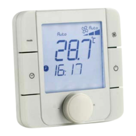
RBW205 is a room control module with room
temperature sensor, manual setting of the room temper-
ature setpoint and LED status to use on a controller
RCN.
Variant with a graded range of functions are available:
Set room temperature, manual and automatic fan control,
presence button (present/absent).
Content Page
Important Information Regarding Product Safety ..................................................................................................2
Item........................................................................................................................................................................3
Technical Data.....................................................................................................................................................3
Accessories (not included in delivery) .................................................................................................................3
Dimensions..........................................................................................................................................................4
Connection...........................................................................................................................................................5
Mounting ................................................................................................................................................................6
Using the Software ................................................................................................................................................8
Setting the room temperature..............................................................................................................................8
Energy saving mode............................................................................................................................................8
CAN Address Setting.............................................................................................................................................9
Installation..............................................................................................................................................................9
Notes for service technicians.................................................................................................................................9

Page 2 / 10
Product DescriptionRBW205
Technical brochure NA 14-52A
Important Information Regarding Product Safety
Safety Instructions
This data sheet contains information on installing and commissioning the product "RBW205".
Each person who carries out work on this product must have read and understood this data sheet. If
you have any questions that are not resolved by this data sheet, you can obtain further information
from the supplier or manufacturer.
If the product is not used in accordance with this data sheet, the protection provided will be impaired.
Applicable regulations must be observed when installing and using the device. Within the EU, these
include regulations regarding occupational safety and accident prevention as well as those from the
VDE (Association for Electrical, Electronic & Information Technologies). If the device is used in other
countries, it is the responsibility of the system installer or operator to comply with local regulations.
Mounting, installation and commissioning work on the devices may only be carried out by qualified
technicians. Qualified technicians are persons who are familiar with the described product and who
can assess given tasks and recognize possible dangers due to technical training, knowledge and
experience as well as knowledge of the appropriate regulations.
Legend
WARNING
Indicates a hazard of medium risk which can result in death or severe bodily injury if it is not avoided.
CAUTION
Indicates a hazard of low risk which can result in minor or medium bodily injury if it is not avoided.
!CAUTION
Indicates a hazard of medium risk which can result in material damage or malfunctions if it is not
avoided.
NOTE
Indicates additional information that can simplify the work with the product for you.
Notes on Disposal
For disposal, the product is considered waste from electrical and electronic equipment (electronic
waste) and must not be disposed of as household waste. Special treatment for specific components
may be legally binding or ecologically sensible. The local and currently applicable legislation must be
observed.

Page 3 / 10
RBW205Product Description
Item
Technical Data
RBW205 Room control module with room temperature sensor, setting of room tem-
perature setpoint made using knob (with LED indicator) with presence but-
ton, buttons for fan control (higher/lower), button for automatic fan mode,
each with LED indicators
Nominal voltage DC 12 V ± 20%, 0.72 W
Power consumption 0.6 W (LEDs switched off), 0.72 W (LEDs switched on)
Measured value Room temperature of spaces in homes or commercial premises
Measuring system Integrated digital room sensor
Controls Knob for setting room temperature setpoint
Keys:
Fan control level increasing: Fan on, increased speed
Fan control level decreasing: Decreased speed, fan off
Fan in automatic mode (fan speed specified by controller)
Presence button (power save button): Switch to present or absent
Indicator Red LED: higher room temperature setpoint
Blue LED: lower room temperature setpoint
Green LEDs: Feedback for fan level , automatic mode, presence button
(present)
Interfaces CAN bus, 4-wire terminal or RJ9
Measuring range 0 °C to 50 °C
Relative measuring accu-
racy
0.1 K
Housing Plastic housing, RAL 9010 (pure white)
Other colors on request
Protection class III
Degree of protection IP30
Ambient temperature 0 °C to 50 °C
Ambient humidity During operation: 20% to 80% r.h.; non-condensing
Out of operation: 5% to 90% r.h.; non-condensing
Installation Screw mounting on standard flush-mounted box
Weight 0.1 kg
Dimensions WxHxD mm 90 x 90 x 32,5
Depth in wall 9.5

Page 4 / 10
Product DescriptionRBW205
Technical brochure NA 14-52A
Dimensions
90.0 23,0
16,0
90,0
9,5
Ø50

Page 5 / 10
Technical brochure NA 14-52A
RBW205Product Description
Connection
Sample connection
+12V=
C–
RJ
0V
C+
17 18 19 20
59 6057 58
1817
L1N
2
1
Y4 0V
786
5
41110 12
9
32 33 34 35
30 31
26 27 28 29
24 25 50 51
BA
LON
Y2 +24V
0V RJ
230V~
10 A
K10
K2K1
24V~/
230V~
K7 K8 K9
3 A (2 A)
24V~/
230V~
24V~/
230V~
P5 P6
0..10V
+
+
P1 P2
KP10
++
P3 P4
NTC10K
max. 0,4 A
+12V=
0V
C+
Cí
17 18 19 20

Page 6 / 10
Product DescriptionRBW205
Technical brochure NA 14-52A
Mounting
!CAUTION
Installation and removal may only be carried out by qualified technicians when the power is switched
off.
Choose an installation location that is subject to the air flow of the room to ensure that the room
controller can quickly and accurately measure the room temperature.
Installation on a standard flush-mounted box (RJ9 connector)
1,5m
= 0,5m
≤ 2,5
1 2
Z178
3 4
5 6

Page 7 / 10
Technical brochure NA 14-52A
RBW205Product Description
Installation on a standard flush-mounted box (4-wire connection to terminal)
1 2 3 4
5 6

Page 8 / 10
Product DescriptionRBW205
Technical brochure NA 14-52A
Using the Software
NOTE
The control module switches to standby mode after 10 seconds: All LEDs are switched off.
To make settings: Press any key or rotate the knob.
Setting the room temperature
If you turn the knob, the function is activated:
Rotate the knob to the left: Reduce the temperature.
Rotate the knob to the right: Increase the temperature.
Depending on the selected temperature setting, the display of the LEDs changes.
Neither of the two LEDs is illuminated: The average value is set.
Blue LED illuminated: Increase by degrees (°C) to full intensity (-3°C in comparison to the
average value).
Red LED illuminated: Decrease by degrees (°C) to full intensity (+3°C in comparison to the
average value).
Energy saving mode
If you leave the room for a longer period of time, switch the presence button to “Absent”, LED
(OFF).
The energy saving function is activated and the temperature is set to a preconfigured value
(cannot be adjusted).
When you return to the room, switch the presence button to “Present”, LED (ON).
The energy saving function is switched off. You can adjust the temperature to a value of your
choice.
1 Knob Rotate: Set the value (e.g. temperature). Left: Lower it (blue LED).
Right: Raise it (red LED)
2 Presence button (power save button): Switch between “Present” and
“Absent”. Green LED (ON): “Present”
3 Fan in automatic mode: Fan speed specified by the controller. Green
LED (ON)
4 Reduce the speed, fan off. Four green LEDs: Max. to min. fan level
display
5 Fan on, increase speed. Four green LEDs: Min. to max. fan level dis-
play
5
4
3
2
1

Page 9 / 10
Technical brochure NA 14-52A
RBW205Product Description
CAN Address Setting
The address switch (1) is located on the PCB of the room control module (rear of device).
Address setting:
The address 1 is factory set and is automatically detected by RCN.
1 Address switch
Installation
Online installation via technolon® room controller RCN:
The technolon® room controller RCN can also be identified quickly and easily directly on the
room control module using a magnet (3). A magnet (3) is guided along the right side of room control
module RCN.
This triggers the service PIN in room controller RCN internally. This is indicated by a service
LED (4) on the top part of the housing on the room control modules that lights up green.
Notes for service technicians
Additional indicators
The red and blue LEDs on the knob remain illuminated: Field bus error (short circuit, interchanged
bus).
After interruption of the power supply, red and blue LEDs illuminate for approx. eight seconds until
the device is logged on.
The LED on the top part of the housing under the ventilation slots illuminates briefly once: When
logging onto the controller through the triggering of the dry reed contact on the external wall of the
housing (using magnets).
1
3
4

Page 10 / 10
Product DescriptionRBW205
Technical brochure NA 14-52A
Table of contents
Other CIAT Controllers manuals
Popular Controllers manuals by other brands

Matelec
Matelec FPC-12725 Owner's operation manual

Azbil
Azbil AUR890 Series specification

Allen-Bradley
Allen-Bradley PowerFlex 525 user manual

HP
HP StorageWorks HSG60 installation instructions

ABB
ABB C505 user guide

Siemens
Siemens Raja+ 3TE7431-2BC24-1A Series Installation, Maintenance & Troubleshooting Guide