Cincoze DS-1200 Series User manual

Rugged Embedded Computer
9/8th Generation Intel® Core™ Series Processors
High Performance, Expandable and Modular Rugged
Embedded Computer
Version: V1.43
DS-1200 Series
User Manual
Rugged Embedded Computer

DS-1200 Series | User Manual 2
Contents
Preface
Revision……………………………………………..……………….……………...……………...05
Copyright Notice.…………………………………………………………………………………...05
Acknowledgement.……………………………………………………………….........................05
Disclaimer.………………………………………………………………….………………...........05
Declaration of Conformity.………………………………………………….……………………05
Product Warranty Statement …………………………………………………………….............06
Technical Support and Assistance.…………………………………………….…………………07
Conventions Used in this Manual …………………………………………….…………............08
Safety Precaution …...……………………………………………….………….………..............08
Package Contents ………………………………………………………….…….………...……10
Ordering Information …………………………………...…………………….…….……...……...10
Optional Modules & Accessories……………………………………........................................11
Chapter 1 Product Introductions
1.1 Overview …………………………………………………….……......……………..............13
1.2 Highlights …………………………………………………….…………....……………........13
1.3 Product Pictures……...……………………………………….……………………..............14
1.4 Key Features …………………..................………………….…………………….…..........14
1.5 Hardware Specification ……………..……………………….……...………………....……15
1.6 System I/O ……………………………………......…………….……………………............16
1.6.1 Front ……………………………………......…………………………………………..16
1.6.2 Rear ………….………………………………….………………………….......………18
1.7 Mechanical Dimension …………………………………….………...………......……........20
Chapter 2 Switches and Connectors
2.1 Location of Switches and Connectors ………….………………………………...………..23
2.1.1 Top View ……………………………….……………………………………...………..23
2.1.2 Bottom View ……………………………………………………………...……............24
2.2 Switches and Connectors Definition…………………..….……………………………….25
2.3 Definition of Switches.……...……………..............................................……..................26
2.4 Definition of Connectors …...….……...……….............……………….............................27
Chapter 3 System Setup
3.1 Removing the Top Cover ……...……………………………….….…………………..........35
3.2 Installing CPU ………………………………………………………………….……………38
3.3 Installing SO-DIMM Memory…………………………………....…………….……………41
3.4 Installing a Mini-PCIe/mSATA Card on Top Side…………………………………..........44
3.5Installing a Mini-PCIe/mSATA Card on Bottom Side……………..…………………...…46

DS-1200 Series | User Manual 3
3.6 Installing Antennas…….…….…………..……….…………………………………………..47
3.7 Installing a SATA Hard Drive on Top Side…………………………………………………50
3.8 Installing an M.2 Card….…….…………..……….…………………………………………..52
3.9 Installing a PCI/PCIe Add-on Card (For DS-1201 and DS-1202 only)….….............54
3.10 Assembling the System….……...……….………...….……………………….…............59
3.11 Installing a SATA Hard Drive at Front Side………...….……………………….…............62
3.12 Installing a SIM Card……….……...……….………...….……………………….…............65
3.13 Installing the CMOS Battery.……...……….………...….……………………….…............66
3.14 Fastening the Cover……….……...……….………...….……………………….…............68
3.15 Wall Mount Brackets……….……...……….………...….……………………….…............69
Chapter 4 BIOS Setup
4.1 BIOS Introduction …….……….…………….…….…..….……………………...................72
4.2 Main Setup ……...……….…..……………….…..….………………........…………...........73
4.2.1 System Date …….……………………………………………...……………..............73
4.2.2 System Time ………..……………………………………………..……….................73
4.3 Advanced Setup ……………………………………………………………………………...74
4.3.1 CPU Configuration……..…………….……………………………………………......74
4.3.2 SATA Configuration……..…………………………………………………………......75
4.3.3 PCH-FW Configuration.………………………...……………………….…................76
4.3.4 Trusted Computing……….…………………...……………………………................76
4.3.5 ACPI Settings ………………………………………………………………………….77
4.3.6 F81866 Super IO Configuration……………………………….…………………....78
4.3.7 Hardware Monitor…………..…………………...……………………….…................79
4.3.8 S5 RTC Wake Settings……………………………………………………………....80
4.3.9 Serial Port Console Redirection……………………………………….……..….....80
4.3.10 USB Configuration………….…………………………………………………..........81
4.3.11 Network Stack Configuration……………..……………..……………………..........82
4.3.12 CSM Configuration……..….……….…………………………………………..........82
4.3.13 NVMe Configuration…..….………….…………………………………………........83
4.4 Chipset Setup …...……….…………………..…..….…..…………………………………...84
4.4.1 System Agent (SA) Configuration ……………..……………………………………..84
4.4.2 PCH-IO Configuration ………………….……………………………………………..85
4.5 Security Setup …...……….………………….…..………………..……………………...…88
4.5.1 Administrator Password …….…...……………………………………………………88
4.5.2 User Password …….…………………………………………………..………………88
4.6 Boot Setup …...……….….……………………………...…..….…..………..………….....89
4.7 Save & Exit …...……….….………………….…..….…..………………………..................90

DS-1200 Series | User Manual 4
Chapter 5 Product Application (For DIO Only)
5.1 Digital I/O (DIO) application ………..………………………………………………………92
5.1.1 Digital I/O Programming Guide ……………………………………………………92
5.2 Digital I/O (DIO) Hardware Specification …………………………………………………104
5.2.1 DIO Connector Definition ………………..……...……………..............................105
Chapter 6 Optional Modules Pin Definitions and Settings
6.1 CMI-COM Connector Definition and Settings……………………...………………………110
6.2 CMI-M12 Connector Definition and Settings……………...…………………………….…111
6.3 CFM-IGN Connector Definition and Settings……………...…………………………….…112
6.4 Installing a Low Speed CMI Module…...…………..……………………………………..113
6.5 Installing a High Speed CMI Module…...…………..……………………………………..116
6.6 Installing a CFM-PoE Module..……….……………………………………………..……..119
6.7 Installing a CFM-IGN Power Ignition Module..……….…………………………………..124
6.8 Installing an External FAN……………………....……….…………………………………..125
6.9 Installing an Internal FAN (For DS-1202 only)...…….…………………………………..127

DS-1200 Series | User Manual 5
Preface
Revision
Revision
Description
Date
1.00
First Release
2018/10/23
1.10
Correction Made
2018/11/20
1.20
Update the Supporting Capacity of Memory to the
latest
2019/11/08
1.21
Correction Made
2019/11/21
1.30
Correction Made
2019/12/18
1.40
Add the latest supported processors
2019/12/31
1.41
Correction Made
2020/01/14
1.42
Correction Made
2020/04/09
1.43
New Format Updated
2020/10/22
1.44
Correction Made
2020/11/13
Copyright Notice
© 2018 by Cincoze Co., Ltd. All rights are reserved. No parts of this manual may be copied,
modified, or reproduced in any form or by any means for commercial use without the prior
written permission of Cincoze Co., Ltd. All information and specification provided in this
manual are for reference only and remain subject to change without prior notice.
Acknowledgement
Cincoze is a registered trademark of Cincoze Co., Ltd. All registered trademarks and product
names mentioned herein are used for identification purposes only and may be trademarks
and/or registered trademarks of their respective owners.
Disclaimer
This manual is intended to be used as a practical and informative guide only and is subject
to change without notice. It does not represent a commitment on the part of Cincoze. This
product might include unintentional technical or typographical errors. Changes are
periodically made to the information herein to correct such errors, and these changes are
incorporated into new editions of the publication.
Declaration of Conformity
FCC
This equipment has been tested and found to comply with the limits for a Class
A digital device, pursuant to Part 15 of the FCC Rules. These limits are
designed to provide reasonable protection against harmful interference when

DS-1200 Series | User Manual 6
the equipment is operated in a commercial environment. This equipment
generates, uses, and can radiate radio frequency energy and, if not installed
and used in accordance with the instruction manual, may cause harmful
interference to radio communications. Operation of this equipment in a
residential area is likely to cause harmful interference in which case the user
will be required to correct the interference at his own expense.
CE
The product(s) described in this manual complies with all application European
Union (CE) directives if it has a CE marking. For computer systems to remain
CE compliant, only CE-compliant parts may be used. Maintaining CE
compliance also requires proper cable and cabling techniques.
E-Mark
The "E" mark is based on ECE regulations issued by the Economic
Commission for Europe. It is an organizational part of the UN and the
members are EU countries and many others. Therefore, the acceptance of
approved components is much broader, especially in the eastern part of
Europe. It is necessary to confirm whether a particular country has accepted
(signed) the application of an ECE-regulation; as the application it is not
mandatory for the countries.
Product Warranty Statement
Warranty
Cincoze products are warranted by Cincoze Co., Ltd. to be free from defect in materials and
workmanship for 2 years from the date of purchase by the original purchaser. During the
warranty period, we shall, at our option, either repair or replace any product that proves to be
defective under normal operation. Defects, malfunctions, or failures of the warranted product
caused by damage resulting from natural disasters (such as by lightening, flood, earthquake,
etc.), environmental and atmospheric disturbances, other external forces such as power line
disturbances, plugging the board in under power, or incorrect cabling, and damage caused
by misuse, abuse, and unauthorized alteration or repair, and the product in question is either
software, or an expendable item (such as a fuse, battery, etc.), are not warranted.
RMA
Before sending your product in, you will need to fill in Cincoze RMA Request Form and
obtain a RMA number from us. Our staff is available at any time to provide you with the most
friendly and immediate service.
◼RMA Instruction
⚫Customers must fill in Cincoze Return Merchandise Authorization (RMA)
Request Form and obtain an RMA number prior to returning a defective

DS-1200 Series | User Manual 7
product to Cincoze for service.
⚫Customers must collect all the information about the problems encountered
and note anything abnormal and describe the problems on the “Cincoze
Service Form” for the RMA number apply process.
⚫Charges may be incurred for certain repairs. Cincoze will charge for repairs to
products whose warranty period has expired. Cincoze will also charge for
repairs to products if the damage resulted from acts of God, environmental or
atmospheric disturbances, or other external forces through misuse, abuse, or
unauthorized alteration or repair. If charges will be incurred for a repair,
Cincoze lists all charges, and will wait for customer’s approval before
performing the repair.
⚫Customers agree to insure the product or assume the risk of loss or damage
during transit, to prepay shipping charges, and to use the original shipping
container or equivalent.
⚫Customers can be sent back the faulty products with or without accessories
(manuals, cable, etc.) and any components from the system. If the
components were suspected as part of the problems, please note clearly
which components are included. Otherwise, Cincoze is not responsible for the
devices/parts.
⚫Repaired items will be shipped along with a "Repair Report" detailing the
findings and actions taken.
Limitation of Liability
Cincoze’ liability arising out of the manufacture, sale, or supplying of the product and its use,
whether based on warranty, contract, negligence, product liability, or otherwise, shall not
exceed the original selling price of the product. The remedies provided herein are the
customer’s sole and exclusive remedies. In no event shall Cincoze be liable for direct,
indirect, special or consequential damages whether based on contract of any other legal
theory.
Technical Support and Assistance
1. Visit the Cincoze website at www.cincoze.com where you can find the latest information
about the product.
2. Contact your distributor or our technical support team or sales representative for
technical support if you need additional assistance. Please have following information
ready before you call:
⚫Product name and serial number
⚫Description of your peripheral attachments
⚫Description of your software (operating system, version, application software, etc.)
⚫A complete description of the problem
⚫The exact wording of any error messages

DS-1200 Series | User Manual 8
Conventions Used in this Manual
Safety Precautions
Before installing and using this device, please note the following precautions.
1. Read these safety instructions carefully.
2. Keep this User’s Manual for future reference.
3. Disconnected this equipment from any AC outlet before cleaning.
4. For plug-in equipment, the power outlet socket must be located near the equipment and
must be easily accessible.
5. Keep this equipment away from humidity.
6. Put this equipment on a reliable surface during installation. Dropping it or letting it fall
may cause damage.
7. Make sure the voltage of the power source is correct before connecting the equipment
to the power outlet.
8. Use a power cord that has been approved for using with the product and that it matches
the voltage and current marked on the product’s electrical range label. The voltage and
current rating of the cord must be greater than the voltage and current rating marked on
the product.
9. Position the power cord so that people cannot step on it. Do not place anything over the
power cord.
10. All cautions and warnings on the equipment should be noted.
11. If the equipment is not used for a long time, disconnect it from the power source to avoid
damage by transient overvoltage.
12. Never pour any liquid into an opening. This may cause fire or electrical shock.

DS-1200 Series | User Manual 9
13. Never open the equipment. For safety reasons, the equipment should be opened only
by qualified service personnel.
If one of the following situations arises, get the equipment checked by service
personnel:
⚫The power cord or plug is damaged.
⚫Liquid has penetrated into the equipment.
⚫The equipment has been exposed to moisture.
⚫The equipment does not work well, or you cannot get it work according to the user's
manual.
⚫The equipment has been dropped and damaged.
⚫The equipment has obvious signs of breakage.
14. CAUTION: Danger of explosion if battery is incorrectly replaced. Replace only with the
same or equivalent type recommended by the manufacturer.
15. Equipment intended only for use in a RESTRICTED ACCESS AREA.

DS-1200 Series | User Manual 10
Package Contents
Before installation, please ensure all the items listed in the following table are included in the
package.
Item
Description
Q’ty
1
Embedded System
1
2
Utility DVD Driver
1
3
Heat Sink Pack
1
4
Screw Pack
1
5
Wall Mounting Kit
1
6
Power Terminal Block Connector
1
7
Remote Power On/Off Terminal Block Connector
1
8
Remote Power Reset Terminal Block Connector
1
9
Fan Terminal Block Connector
1
10
DVI-I to VGA Adaptor
1
Note: Notify your sales representative if any of the above items are missing or damaged.
Ordering Information
Model No.
Product Description
DS-1200-R10
9/8th Generation Intel® Core™ Series Processors, High
Performance, Expandable and Modular Rugged Embedded
Computer
DS-1201-R10
9/8th Generation Intel® Core™ Series Processors, High
Performance, Expandable and Modular Rugged Embedded
Computer with 1x PCI/PCIe Expansion Slots
DS-1202-R10
9/8th Generation Intel® Core™ Series Processors, High
Performance, Expandable and Modular Rugged Embedded
Computer with 2x PCI/PCIe Expansion Slots

DS-1200 Series | User Manual 11
Optional Modules & Accessories
Model No.
Product Description
CFM-PoE03
CFM Module with PoE Control Function, Individual Port 25.5W
CFM-IGN101
CFM Module with Power Ignition Sensing Function, 12V/24V Selectable for DS-1200/
DS-1100/ P1101 Series
CMI-LAN01-R12/UB1012
CMI Module with 4x Intel I210-IT GbE LAN, RJ45 Port / 1x Universal Bracket with 4x
RJ45 Cutout for DS-1200 Series
CMI-M12LAN01-R12
/UB1010
CMI Module with 4x Intel I210-IT GbE LAN, M12 Connector / 1x Universal Bracket with
4x M12 Cutout for DS-1200 Series
CMI-DIO02/UB1018
CMI Module with 16DIO (8in 8out), 1x Universal Bracket with DIO Cutout for DS-1200
Series
CMI-COM02/UB1004
CMI Module with 4 x RS232/422/485 (Support 5V/12V), 1x Universal Bracket with 4x
DB9 Cutout for DS-1200 Series
CMI-ICOM01/UB1004
CMI Module with 4 x isolated RS232/422/485 (Support 5V/12V), 1x Universal Bracket
with 4x DB9 Cutout for DS-1200 Series
MEC-COM-M212-DB9/UB03
03
Mini-PCIe Module with 2x COM Ports, 1x Standard DB9 Cable, 2x Universal Bracket
each with 1x DB9 Cutout for DS / P1000 Series
MEC-USB-M102-15/UB0314
Mini-PCIe Module with 2x USB 3.0 Ports, 1x 15cm cable, 1xUniversal Bracket with 2x
USB Cutout for DS Series
MEC-LAN-M102-30/UB0311
Mini-PCIe Module with 2x LAN Ports, 2x 30cm cable, 1x Universal Bracket with 2x
RJ45 Cutout for DS Series
FAN-EX101
External Fan with 4pin Terminal Block Plug, Mounting Bracket, Support Smart Fan
FAN-UB100
Exhaling Fan with 4pin Connector, Universal Bracket
FAN-UB101
Inhaling Fan with 4pin Connector, Universal Bracket
PAH01
Power Adapter Holder for GST120A24
PAH02
Power Adapter Holder for GST220A24
GST120A24-CIN
Adapter AC/DC 24V 5A 120W, with 3pin Terminal Block Plug 5.0mm Pitch, with
TUBES, level VI
GST220A24-CIN
Adapter AC/DC 24V 9.2A 220W with 3pin Terminal Block Plug 5.0mm Pitch, with
TUBES, level VI
RC-E16-01
Riser Card with 1x PCIex16 Slot for DS-1201
RC-PI-01
Riser Card with 1x PCI Slot for DS-1201
RC-E8E8-01
Riser Card with 2x PCIex8 Slots for DS-1202
RC-E16E1-01
Riser Card with 1x PCIex16 and 1x PCIex1 Slots for DS-1202
RC-E16PI-01
Riser Card with 1x PCIex16 and 1x PCI Slots for DS-1202
RC-PIPI-01
Riser Card with 2x PCI Slots for DS-1202

DS-1200 Series | User Manual 12
Chapter 1
Product
Introductions

DS-1200 Series | User Manual 13
1.1 Overview
DS-1200 series is a high performance fanless embedded computer, powered by 9/8th generation
Intel® Core™ processor (Coffee Lake) with up to 8 cores and 64GB DDR4 memory capacity for
unprecedented performance to fulfill all kinds of high-end computing requirements. The system also
incorporates rich I/O, such as 2x Intel® GbE ports, 2x USB 3.1 (Gen2), 4x USB 3.0, 1x DVI-I, 2x
DisplayPort, and 1x M.2 Key M 2280 socket for ultra-fast data transfer speed.
Based on Cincoze’ innovative CMI & CFM Technology, it allows users to expand I/O and
functionalities through ready-to-use modules, such as GbE/PoE ports, serial ports, optical isolated
digital I/O and power ignition function. Furthermore, DS-1200 series supports maximum 2 PCI(e)
expansion slots to accommodate versatile add-on cards.
Designed to operate under harsh conditions, DS-1200 series has passed rigorous testing like
EN50155 (EN50121-3-2) and EN60950-1 to fulfill industrial applications such as rolling stock.
Besides, DS-1200 series features with wide operating temperature (-40°C to 70°C), wide range DC
power input (from 9V to 48V), high tolerance of shock/vibration (5G/50G), and industrial-grade
protections (OVP, OCP, ESD Surge, ...etc).
1.2 Highlights
High Performance
The new 9/8th generation Intel® Core™ processor (Coffee Lake)
offers for the first time up to 8 cores, 16 threads and 1.4 times
computing performance improvement comparing to the previous
generation (Kaby Lake).
Fully Modular and Expandable
Featuring PCI/PCIe expansion slots, Mini-PCIe slots, CMI (Combined
Multiple I/O), CFM (Control Function Module), and
versatile ready-to-use modules, DS-1200 series provides great
flexibility to configure the system according to your need.
Wide Temperature
DS-1200 series is designed for continuous operation in wide
temperature range from -40°C to 70°C. In addition, it also features
with anti-shock/vibration and ESD/surge protection for tough industrial
environments.

DS-1200 Series | User Manual 14
1.3 Product pictures
DS-1200
DS-1201
DS-1202
Front
Rear
1.4 Key Features
⚫Supports 9/8th Gen Intel® Core™ / Pentium® / Celeron® Octa Cores 35W/65W LGA
1151 Processors
⚫2x DDR4 SO-DIMM Socket, Supports Up to 2666MHz, 64GB
⚫Triple Independent Displays: 1x DVI-I and 2x DP (4K Resolution)
⚫1x M.2 2280 M Key Socket, Auto-detection for PCIex4 NVMe SSD or SATA Gen3 SSD
⚫2x Front Accessible SIM Card Slots for Signal Redundancy
⚫2x PCI/PCIe Slots for Add-on Cards (Maximum Length: 235mm) (For DS-1201 &
DS-1202 only)
⚫4x CMI Slots for Modular I/O Expansions
⚫1x CFM Slot for Power Ignition Sensing Function
⚫Wide Operating Temperature (-40°C to 70°C )
⚫EN50155 (EN50121-3-2) / EN60950-1 Certified

DS-1200 Series | User Manual 15
1.5 Hardware Specification
Processor
• 9th Generation Intel® Coffee Lake-R S Series CPU:
- Intel® Core™ i7-9700E 8 Cores Up to 4.4 GHz, TDP 65W
- Intel® Core™ i5-9500E 6 Cores Up to 4.2 GHz, TDP 65W
- Intel® Core™ i3-9100E 4 Cores Up to 3.7 GHz, TDP 65W
- Intel® Core™ i7-9700TE 8 Cores Up to 3.8 GHz, TDP 35W
- Intel® Core™ i5-9500TE 6 Cores Up to 3.6 GHz, TDP 35W
- Intel® Core™ i3-9100TE 4 Cores Up to 3.2 GHz, TDP 35W
• 8th Generation Intel® Coffee Lake S Series CPU:
- Intel® Core™ i7-8700 6 Cores Up to 4.6 GHz - 12M Cache, TDP 65W
- Intel® Core™ i5-8500 6 Cores Up to 4.1 GHz - 9M Cache, TDP 65W
- Intel® Core™ i3-8100 4 Cores 3.6 GHz - 6M Cache, TDP 65W
- Intel® Core™ i7-8700T 6 Cores Up to 4.0 GHz - 12M Cache, TDP 35W
- Intel® Core™ i5-8500T 6 Cores Up to 3.5 GHz - 9M Cache, TDP 35W
- Intel® Core™ i3-8100T 4 Cores 3.1 GHz - 6M Cache, TDP 35W
- Intel® Pentium® G5400 2 Cores 3.7 GHz - 4M Cache, TDP 58W
- Intel® Pentium® G5400T 2 Cores 3.1 GHz - 4M Cache, TDP 35W
- Intel® Celeron® G4900 2 Cores 3.1 GHz - 2M Cache, TDP 54W
- Intel® Celeron® G4900T 2 Cores 2.9 GHz - 2M Cache, TDP 35W
Chipset
• Intel® Q370
BIOS
• AMI 32MB SPI BIOS
Memory
• 2x DDR4-2400/2666 MHz SO-DIMM Sockets, Supports up to 64 GB
(Un-buffered and Non-ECC Type)
* DDR4 2666MHz memory modules are only for Core™ i7/i5 Processors
Graphics
• Integrated Intel® UHD Graphics 630: Core™ i7/i5/i3
• Integrated Intel® UHD Graphics 610: Pentium® /Celeron®
• Supports Triple Independent Display (1x DVI-I, 2x DisplayPort)
Audio
• Realtek® ALC888
• High Definition Audio
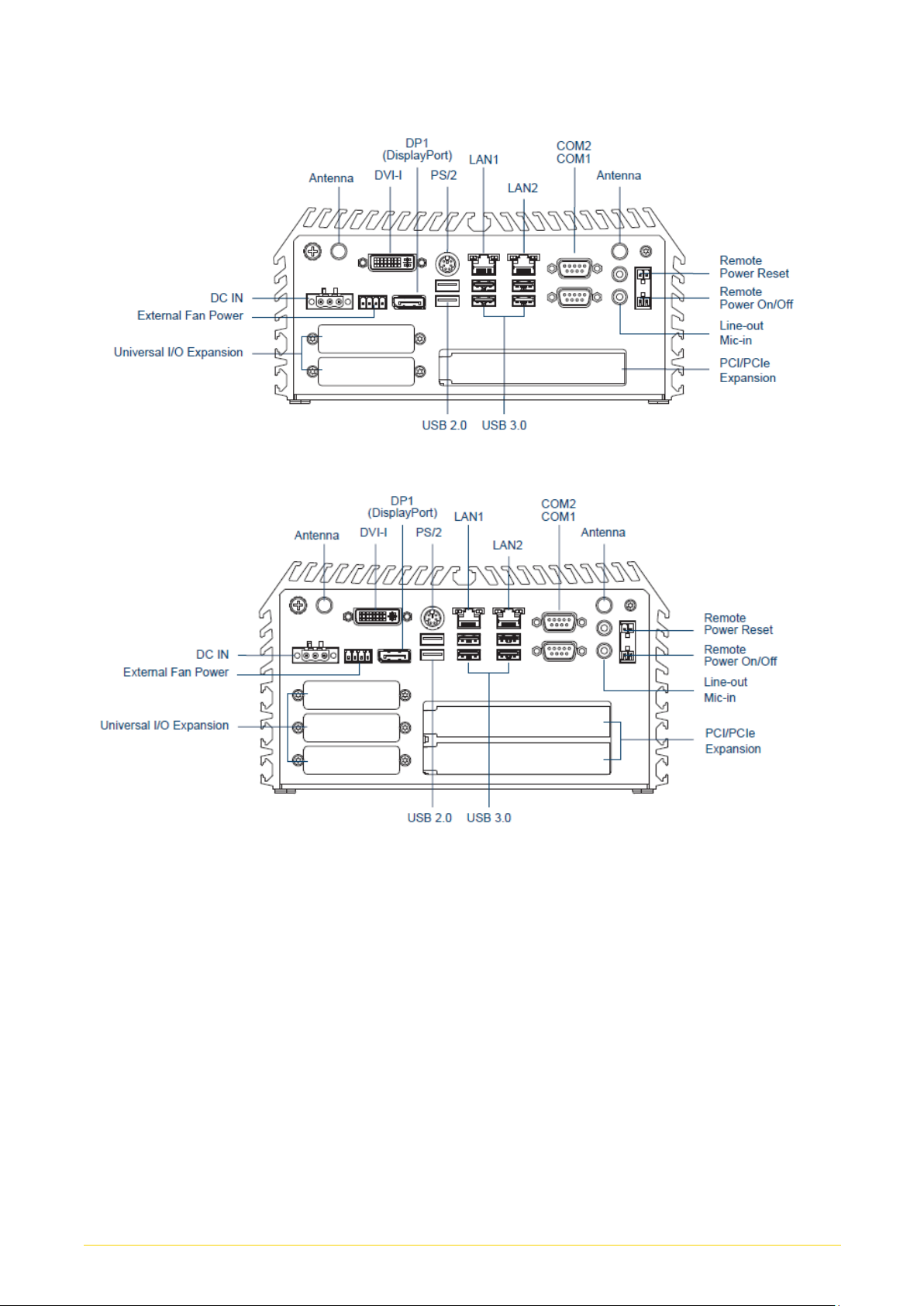
External I/O Interface
• 1x DVI-I (DVI-D: 1920 x 1200 @60Hz / VGA: 1920 x 1080 @60Hz)
• 2x DisplayPort (DisplayPort: 4096 x 2304 @60Hz)
• 2x GbE LAN (Supports WoL, Teaming, Jumbo Frame & PXE), RJ45
- GbE1: Intel® I210-IT
- GbE2: Intel® I219-LM
• 2x USB 3.1 Gen2 (Type A)
• 4x USB 3.0 (Type A)
• 2x USB 2.0 (Type A)
• 2x RS-232/422/485 with Auto Flow Control (Supports 5V/12V), DB9
• 1x PS/2, 6-pin mini-DIN Female Connector
• 1x Line-out & 1x Mic-in, Phone Jack 3.5mm
• 1x ATX Power On/Off Button
• 1x AT/ATX Mode Switch
• 1x Clear CMOS Switch
• 1x Remote Reset Connector, 2-pin Terminal Block
• 1x Remote Power On/Off Connector, 2-pin Terminal Block
• 1x External Fan Connector, 4-Pin Terminal Block (Supports smart fan by BIOS)
Storage
• 2x 2.5" SATA HDD/SSD bay (Gen3), 1x Internal, 1x Front Accessible Supports
RAID 0/1
• 3x mSATA (shared by Mini-PCIe socket) (Gen3), BIOS Selectable
• 1x M.2 Key M 2280 Socket, Supports PCIe x4 NVMe SSD or SATA SSD (Gen3)
Expansion
• 3x Full-size Mini-PCIe Socket
• 2x SIM Socket
• 1x CFM (Control Function Module) Interface
• 2x CMI (Combined Multiple I/O) High Speed Interface
• 2x CMI (Combined Multiple I/O) Low Speed Interface
• 2x Antenna Hole
• 1x PCI/PCIe Expansion slot (with Optional Riser Card) (For DS-1201)
* Supports maximum dimensions of add-on card (H x L):111.15 x 235mm
• 2x PCI/PCIe Expansion slot (with Optional Riser Card) (For DS-1202)
* Supports maximum dimensions of add-on card (H x L):111.15 x 235mm
Other Function
• Supports Instant Reboot Technology (0.2 sec)
• SuperCap Integrated for CMOS Battery Maintenance-free Operation
• Watchdog Timer: Software Programmable Supports 256 Levels System
Reset
Power Requirement
• Supports AT/ATX Power Type
• Power Input Voltage 9~48VDC
• 1x 3-Pin Terminal Block
• Power Adapter AC/DC 24V/5A 120W or 24V/9.2A 220W (Optional)
Physical
• Dimensions(WxDxH):
227 x 261 x 88 mm(DS-1200), 227 x 261 x 108 mm(DS-1201)
227 x 261 x 128 mm (DS-1202)
• Weight: 4.3 kg (DS-1200), 4.92 kg (DS-1201), 5.14 kg (DS-1202)
• Construction: Extruded Aluminum with Heavy Duty Metal
• Mounting: Wall Mount • Unibody Chassis
• Fanless Design • Jumper-less Design
Protection
• Reverse Power Input Protection
• Over Voltage Protection
- Protection Range: 51~58V
- Protection Type: shut down operating voltage, re-power on at the
present level to recover
• Over Current Protection: 15A
• ESD Protection: +/-8kV (air), +/-4kV (contact)
• Surge Protection: 3.84 kV (impedance 12 ohm 1.2/50us waveform)
Operating System
• Windows® 10
• Linux: Supports by project
Environment
• Operating Temperature:
35W TDP Processor: -40°C to 70°C
51~65W TDP Processor: -40°C to 45°C
* PassMark BurnInTest: 100% CPU, 2D/3D Graphics (without thermal throttling)
* With extended temperature peripherals; Ambient with air flow
* According to IEC60068-2-1, IEC60068-2-2, IEC60068-2-14
• Storage Temperature: -40°C to 85°C
• Relative Humidity: 95%RH @ 70°C (non-Condensing)
• Shock: Operating, 50 Grms, Half-sine 11 ms Duration
(w/ SSD, according to IEC60068-2-27)
• Vibration: Operating, 5 Grms, 5-500 Hz, 3 Axes
(With SSD, according to IEC60068-2-64)
• MTBF: 396,565 Hours
Certification
• EMC: CE, FCC Class A
• Safety: LVD, EN60950-1
• Railway: EN50155, EN50121-3-2

DS-1200 Series | User Manual 16
1.6 System I/O
1.6.1 Front
ATX Power On/Off
Used to power-on or power-off the system
AT/ATX Mode Select Switch
Used to select AT or ATX power mode
Power LED
Indicates the power status of the system
Temperature LED
Indicates the temperature of the system
HDD LED
Indicates the status of the hard drive
Digital I/O LED
Indicates the working status of digital input/
output
Ethernet LED
Indicates the status of the LAN ports
USB 3.1 Port
Used to connect USB 3.1/3.0/2.0/1.1 device
DisplayPort
Used to connect the system with DisplayPort
monitor
SIM card, CMOS Battery, and 2.5”
Removable HDD Bay
Used to inserts a SIM card, CMOS battery, and
2.5” HDD
DS-1200

DS-1200 Series | User Manual 17
DS-1201
DS-1202

DS-1200 Series | User Manual 18
1.6.2 Rear
DC IN Terminal Block
Used to plug a DC power input with terminal
block
External Fan Terminal Block
Used to plug an external fan with terminal block
DVI-I Port
Used to connect a DVI monitor or connect
optional split cable for dual display mode
PS/2 Port
Used to connect the PS/2 device
LAN Port
Used to connect to local area network
Display Port
Used to connect a monitor with DisplayPort
interface
USB 3.0 Port
Used to connect USB 3.0/2.0/1.1 device
USB 2.0 Port
Used to connect USB 2.0/1.1 device
Antenna Hole
Used to connect an antenna for optional wireless
module
COM Port
Used to connect to RS-232/422/485 serial
devices
Line-Out
Used to connect a speaker
Mic-In
Used to connect a microphone
Remote Power On/Off & Remote Power
Reset Terminal Block
A terminal block used to connect to remote
power on/off switch
Universal I/O Bracket
Used to customized I/O output
DS-1200

DS-1200 Series | User Manual 19
DS-1201
DS-1202

DS-1200 Series | User Manual 20
1.7 Mechanical Dimension
DS-1200 Unit: mm
DS-1201 Unit: mm
This manual suits for next models
6
Table of contents
Other Cincoze Industrial PC manuals

Cincoze
Cincoze DA-1100 Series User manual

Cincoze
Cincoze DS-1300 Series User manual

Cincoze
Cincoze DE-1000 User manual

Cincoze
Cincoze P2102 Series User manual

Cincoze
Cincoze DE-1000 User manual

Cincoze
Cincoze DS-1202-R10 User manual

Cincoze
Cincoze CV-100/P1100 Series User manual

Cincoze
Cincoze P2002 Series User manual

Cincoze
Cincoze P1201 Series User manual

Cincoze
Cincoze CV-100/P1201 Series User manual