CONNECTIONS
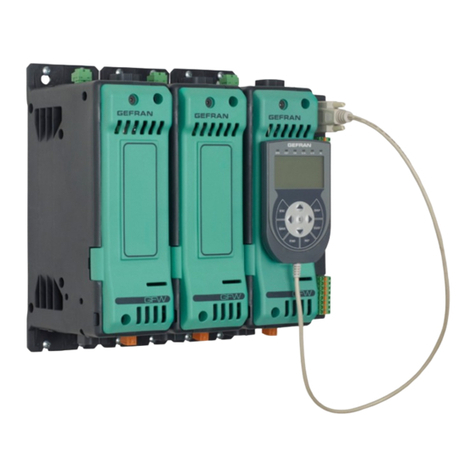
To ensure correct cooling, the minimum horizontal distance to be respected between the power controllers must be
20mm. Where there is overlapping, assemble the power units in a quincuncial layout and leave sufficient vertical space
(approximately 100 mm) to facilitate the connections.
• THE DEVICES CAN BE FASTENED:
- normally on DIN RAIL. For sizes from 75 to 150A it is advisable to assemble a second bar to be used as a support, to
prevent the anchor bar from bending under the unit’s weight.
- On a panel, using a fixing plate supplied as an option and available only for models 75A, 100A and 150A.
• GENERAL PRECAUTIONS
The power controllers are not sectioning or insulating devices.
In order to guarantee functional safety, it is advisable to:
- install a general power supply switch-off system which ensures the insulation between the device and the network.
- Connect the heatsink of the power controllers from 25 to 150 A to earth before carrying out all other connections, and
before disconnecting it or carrying out any intervention on the unit.
Assemble a protection device suitable for the installation features (automatic switch, fuses, …)
The ultra rapid fuses usually proposed as an option only provide protection for the thyristors of the unit and do not
ensure complete protection of the instrument.
The installation and wiring must be carried out in full compliance with the standards in force. Special care must be taken to
keep the power cables separate from the control cables along their entire length. The control signals connection must be
done with shielded cables where the shield is earthed to a single point, preferably on the side of the origin of the signal.
• CONNECTION TERMINAL BOARD
The CAGE power terminals of the unit allow the use of cables with/without crimped terminals.
For 25 and 40A power controllers it is possible to connect in input the two phases or one phase and one neutral. In this
case the inner crossing connection between input 1 and output 3 is used.
ASSEMBLY - FASTENING
The heatsink can reach a high temperature. Any type of contact must be avoided, even accidental, between the
dissipater and the electric connection cables.
!
Fastening, rear view
DIN bar support fastening
2 holes Ø 6,5mm
98mm
PANEL ASSEMBLY KIT
Cod. 1886001
(OPTION for models form 75 to 150A)
It is essential to respect the correct locking torque and choose the cable section which is most suitable for the capacity
used, in order to avoid dangerous overheating of the unit.
!
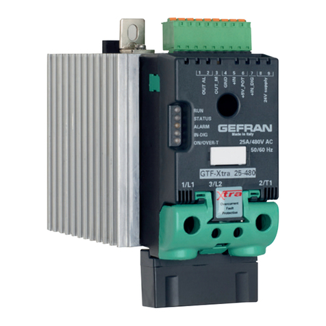
The command and inhibition signals, thermal safety switch, electronics supply are grouped on a black plug-in connector
which allows the use of cables with a cross section ≤1.5 mm2.
The fan include with 150A models is connceted to a 230Vac power supply by means of a specific connector.
Rating A Terminal capacity mm2Tightening torque Nm
25 - 40 from 1,5 to 16 from 1,2 to 1,4
(16 to 6 AWG)
75 - 100 - 150 from 20 to 70 from 6 to 7
(5 to 00 AWG)
485383C_MHW_W312_0709_ENG
