Cirris Signature 1000HN User manual

Signature 1000HN Cable Analyzer
User’s Guide
Version 4.0
Major Revision
1 December, 1999

Signature 1000HN Cable Analyzer User’s Guide
Version 4.0
Major Revision
1 December, 1999
Copyri
g
ht 1999 by Cirris Systems Corporation
1991 Parkway Boulevard
Salt Lake City, Utah 84119-2026
United States of America
All ri
g
hts reserved
Visit our web site at www.cirris.com

I Need Your Help!
As Senior Editor, it’s my responsibility to constantly improve the manuals and other documentation
we include with our equipment. We try hard, but we know we’ll never please everyone. If you were
in my chair, how would you change the documentation to make it better? Here’s your chance to
take gripes, suggestions and (we hope) praise directly to the guy who can change things. Please
fax or mail this form to me, or contact me by e-mail.
Thanks!
Van Nielson
Senior Editor, Technical Documentation
Fax Telephone: 801-973-4609
e-mail: vann@cirris.com
Van Nielson
c/o Cirris Systems Corporation
1991 Parkway Boulevard
Salt Lake City, Utah 84119-2026
U.S.A.
1000HN User’s Guide
Attach more pages if needed


Table of Contents
Introduction to the Cirris 1000HN..................................................................................... 7
Section 1: Work With the Hardware................................................................................. 9
Section 2: Check the Option Settings............................................................................ 17
Section 3: What the Option Settings Mean.................................................................... 19
Section 4: Learn a Sample Cable, Store it in Memory................................................... 23
Section 5: Test Your First Cable.................................................................................... 27
Section 6: Retrieve a Cable from Memory..................................................................... 31
Section 7: Delete a Cable from Memory........................................................................ 33
Section 8: Print a Directory of Cables Stored in Memory............................................... 35
Section 9: Cable Documentation and Signatures.......................................................... 37
Section 10: Select a Test Procedure............................................................................. 43
Section 11: Rework and Guided Assembly.................................................................... 49
Section 12: Troubleshooting.......................................................................................... 55
Section 13: Specifications.............................................................................................. 67
Section 14: Statement of Warranty................................................................................ 69
Section 15: Glossary...................................................................................................... 71
Section 16: Blank Forms to Photocopy.......................................................................... 75


1000HN User’s Guide / page 7
Lets get started! The Cirris 1000HN cable analyzer is an easy-to-use machine that will allow you to
test cables quickly, and with little fuss. In simple terms, the process of using your
1000HN goes like this:
1. Install an expansion box if you want to use one (see page 10 for details). Once
you have installed the box the first time, you probably won’t have to do this
again.
2. Install connector adapters to match the cables you want to test (see page 9 for
details).
3. Check the test option settings; reset the options if you need to (see page 17 for
details).
4. Either:
• Learn a Sample Cable (a cable you know is built correctly) of the kind
you want to test (see page 23 for details), or...
• Retrieve the wirelist data for the kind of cable you want to test from the
analyzer’s memory (see page 31 for details)
This completes programming the analyzer for testing cables. If you have connected a
Sample Cable to learn it, disconnect it now.
5. Connect the first cable you want to test.
6. Test the cable (see page 27 for details).
7. Record and/or or print the test results (see page 30 for details).
That’s it! We’ll show you how to do each of these steps in this manual.
What your order
should contain Your order should contain these things in addition to this manual:
• 1000HN main unit, including a wall transformer with cord, to provide
power for the analyzer.
• Hand-held test probe.
• Whatever connector adapters you have ordered (usually shipped in a 3 x
5-inch card file). You may also have ordered an optional tilt stand, or an
optional frame stand. If so, these should be included.
• An expansion box if you have ordered one.
Introduction
to the Cirris
1000HN

Introduction to the Cirris 1000HN / What your order should contain
1000HN User’s Guide / page 8

1000HN User’s Guide / page 9
The Cirris 1000HN system consists of a main unit, and an optional expansion box. To
connect the cables you want to test to the analyzer, you use connector adapters which
match the connectors on the cable you want to test.
In this section, we will explain how to work with the hardware. We will show you
how to install your connector adapters, how to install the expansion box, and how to
disassemble the analyzer in case you need to replace one of its subassemblies, or its
EPROM.
How to install
connector adapters To install connector adapters onto the Cirris 1000HN, follow these steps:
1. Turn the four twistlock fasteners on the adapter cover plate to unlock them, and
remove the cover plate.
2. Plug in the connector adapters. Be sure the pins on the bottom of each adapter are
lined up properly, so they don’t bend as they are inserted into the sockets. To line
the pins up properly, press the adapter against the inside edge of the metal frame,
and have the bottom of the adapter card resting on the plastic adapter support.
Twistlock fastener unlocked
Twistlock fastener locked
J1
J1
J2
J3
J4
These horizontal pin sockets... accept the adapter connector
pins on the bottom of each
adapter
Section 1:
Work With
the Hardware

Section 1: Work With the Hardware / How to install an expansion box
1000HN User’s Guide / page 10
3. Replace the cover plate, making sure the small alignment pins on its underside fit
into the corresponding holes on the scanner’s upper surface.
4. Lock the twistlock fasteners to hold the adapters firmly in place.
How to install an
expansion box To increase the number of available test points, you can install an expansion box on
your 1000HN. You can set up your system to have as many as 256 test points.
To install an expansion box, follow these steps:
1. Unlock the twistlock fasteners on the top of the analyzer’s spacer and cover
plates, and on the top of the expansion box. Remove the cover plate and the
spacer plate.
2. Lift the scanner assemblies out of both the main unit and the expansion box.
(Note: Your expansion box may have a black plastic plate covering the opening
where you will be routing the scanner cable. Once the scanner has been removed,
push the plastic rivets out from the inside of the chassis, and remove the plastic
plate.)
• For photographic clarity in the top photo, we’ve removed the scanner
assembly from the main unit, and disconnected it. You see the connector
Each cover plate alignment pin...
...fits into a hole in the scanner’s
upper surface.
spacer plate cover plate
Scanner assembly

1000HN User’s Guide / page 11
that plugs into the main unit’s scanner assembly, and the connector that
plugs into the scanner assembly in the expansion box. You also see the
plastic plate in the main unit’s cable routing opening partially removed.
You should remove the plate completely. Make sure the connections to
both the main unit’s scanner and the scanner in the expansion box are
secure.
.
3. Slide the two metal boxes together. The alignment pins in the side of one box
Connector goes to main
scanner
Connector goes to
expansion box scanner
Remove this plastic
plate completely
This view shows the cables that connect the main unit to the expansion
box as they should appear just before you plug them together. Be sure
the connectors are well-seated, and that the connection is secure.
Gently lower both scanners into their boxes, routing the connecting
cables through the openings in the side of each box.

Section 1: Work With the Hardware / How to install an expansion box
1000HN User’s Guide / page 12
should fit into the round openings in the side of the next box.
4. Once the two boxes are in position, hook the drawlatches on one box over the
keepers on the other box, then close the drawlatches to lock the boxes securely
together.
This alignment pin...
...fits into this hole
Once the boxes are together (aligned by the alignment pins and holes)
hook the drawlatches over the keepers on each side of the analyzer,
then snap the drawlatches shut. Replace the coverplates.
Keeper
Drawlatch

1000HN User’s Guide / page 13
5. This photo shows your 1000HN as it should look with an expansion box
installed, and the spacer plate and coverplates in place.
How to change the
EPROM You may need to change the EPROM on the microprocessor assembly. To do this,
follow these steps:
1. Disconnect the wall transformer from the wall outlet, then disconnect the power
cable from the socket on the back of the analyzer.
2. Unlock the twistlock fasteners, remove the spacer plate, then gently raise the
microprocessor assembly out of the box.
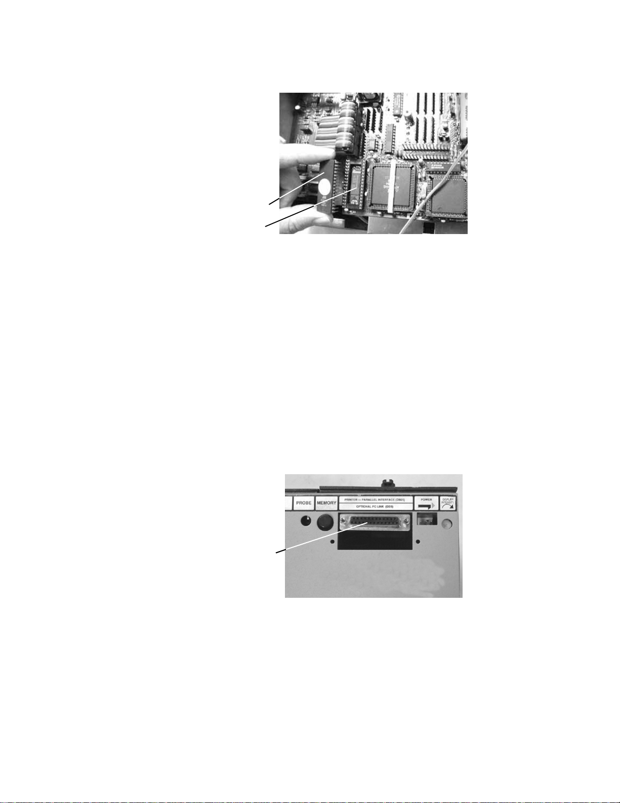
3. Turn the processor assembly over gently. Using a small, flat-bladed screwdriver,
carefully pry the EPROM out of its socket, and remove it.
Remove the spacer plate... ...then lift out the processor assembly
EPROM
Notch
Section 1: Work With the Hardware / Adding a printer
1000HN User’s Guide / page 14
4. Gently align the pins on the new EPROM with the holes in the socket.
5. Carefully push the new EPROM down into the socket using even pressure. Be
careful not to misalign or bend the pins!
6. Gently lower the microprocessor assembly back into the box. Replace the spacer
plate, then lock the twistlock fasteners. Your unit is reassembled.
Adding a printer The 1000HN works with almost any printer that has an Epson/Centronics parallel
interface. WARNING!! Connecting the analyzer to a printer with an RS-232 serial
interface will cause serious damage to the analyzer, and is not covered by your fac-
tory warranty.
To connect the printer, use a standard Epson/Centronic parallel interface cable,
readily available from almost any PC dealer. Plug one end of the cable into the
printer, and the other end into the analyzer’s parallel printer socket as shown in the
photo.
How do I know if I
have a parallel
printer?
To see if you have a parallel printer, look for the parallel connector on the printer.
Printers usually have a parallel interface located in back. Many printers have both a
Gently place the new EPROM on the socket, and align the
pins. Be careful not to bend the pins!
Socket
New EPROM
Plug the printer
in here

1000HN User’s Guide / page 15
serial and a parallel connector. To work with the 1000HN your printer must have a
36-position female ribbon connector similar to the one shown here.
Can I use one printer
with more than one
analyzer?
Yes. To use your printer with more than one analyzer, use a switchbox. To change
which analyzer the printer is receiving information from, simply change the switch
setting on the box.
How do I use a printer
without an on-line/off-
line switch?
If your printer does not happen to have an on-line/off-line switch, you can use either
of two solutions:
• Add a switch by placing a switch in the wire to pin 11 of the Epson/Cen-
tronics printer cable. When pin 11 on either side of the cable is open, the
analyzer will see the printer as being off-line, and will display informa-
tion rather than send it to the printer. When you close the switch so that
pin 11 is closed, information will be sent to the printer.
• If you have a switch box available, you can connect the cable to the
switchbox, and use its switch as the on-line/off-line switch.
Changing the
company name To change the company name that appears in the documentation produced by the
1000HN, you can order an EPROM change from Cirris Systems. Replace the
EPROM. For details on how to do this, see page 13.

Section 1: Work With the Hardware / Changing the company name
1000HN User’s Guide / page 16

1000HN User’s Guide User’s Guide / page 17
Overview: The Cirris 1000HN has eleven test options. Before we learn a Sample Cable, we’ll
make sure they are set to their factory defaults.
How to check the
option settings To check the option settings, do these things:
1. Press in and hold the Display/Printswitch as you turn on the analyzer by
pressing the Onswitch. Hold Display/Print until Ready To Set Up Options
appears.
2. Once Ready To Set Up Options appears in the display, release Display/Print.
3. Select the Create Test From option by pressing Display/Print.
• If the setting is SAMPLE CABLE, go on to the next option by pressing
Display/Print
• To change the option setting, press Function until SAMPLE CABLE
appears, then go on to the next option by pressing Display/Print.
Press and hold...
...then press here
SET UP OPTIONS
READY TO Press to step
Press to change
option settings
through options
Section 2:
Check the
Option
Settings

Section 2: Check the Option Settings / What to do if you go past the value you want
1000HN User’s Guide / page 18
4. Continue stepping through the options by pressing Display/Print, changing the
settings as necessary by pressing Function, until all the options are set as shown
in this table: When you are done, Ready to Learn will appear on the display.
What to do if you go
past the value you
want
If you want to go backward through either the options or settings, press in and hold
the Memorybutton on the back of the analyzer, while pressing Display/Print or
Function. Note: All options or settings will roll over to the beginning when you are
going forward or backward.
.
Your option settings
are saved When you set the value you want, it is saved once it is displayed on the screen.Turn
off the analyzer, the analyzer will use those settings when you power it up again.
Factory Default Option Settings
Option Setting
Create Test From SAMPLE CABLE
Connection Resistance AUTO
Hipot Voltage 300 V
Insulation Resistance 10 MΩ
Hipot Duration 100mS
Apply Hipot to ALL ADAPTER PINS
Auto Hipot OFF
Error Tones are LOW
Sorted Wire List is OFF
Count All Cables is OFF
Auto Print is OFF
Memory button

1000HN User’s Guide / page 19
Overview The Cirris 1000HN has eleven test option settings which you set to meet your testing
requirements. In this section, we’ll tell you what each of the settings means.
Create Test From Gives you the option to create a new test setup from a new Sample Cable, your last
test setup, or by learning a complex cable that contains resistors and/or diodes in addi-
tion to ordinary wire connections.
SAMPLE CABLE: Use this setting to learn standard simple cables (cables that
contain only wires and connectors).
LAST TEST SETUP: Use this setting when you need to use the same test setup each
time you turn on the analyzer. Useful when testing large batches of the same type
cable. Will help protect your test setup from a power failure, or if you accidentally
turn on the analyzer with an untested cable connected.
COMPLEX ASSEMBLY: Use this setting to learn a cable that contains resistors,
diodes, or divider networks in addition to ordinary wires and connectors. When you
use this setting, the Connection Resistance refers to the resistance level that definitely
separates wires from resistors. The analyzer sets this to 5 Ω. You may change the
setting to meet your needs. Using the Connection Resistance CALC mode may help
you determine a good setting.
Connection
Resistance Specifies the maximum resistance a connection can have and still be considered
good. For example, if you set the Connection Resistance to 10 Ω, the analyzer will
consider all connections with resistances less than 10 Ωas good, and those with resis-
tances greater than 10 Ωas bad.
Range:.5Ω, 1Ω, 2Ω, 5Ω, 10Ω, 20Ω,50Ω, 100Ω, 200Ω, 500Ω, 1ΚΩ, AUTO, CALC.
AUTO mode: When you set the Connection Resistance to AUTO, the 1000HN
measures the resistance of each connection in your Sample Cable, then automatically
sets the Connection Resistance threshold to a value 20% higher than the largest
resistance measured in the Sample Cable. The 20% margin of error is increased for
resistances less than 1Ω.
CALC mode: Setting the Connection Resistance to CALCcauses the 1000HN to
measure the resistance of the connections in the Sample Cable in the same way you
would measure them with an ohmmeter. In this mode, the analyzer can only measure
resistances up to 6KΩ. After the analyzer calculates the resistance of the Sample
Cable, it prompts RESISTANCE READY. Press the Display/Printswitch to display
all resistances measured below 6Kohms.
Hipot Voltage Range: Off, 50V, 100V, 200V, 300V, 400V, 500V, 630V. Specifies what voltage will
be applied during hipot testing, between pins that should not be connected. This deter-
Section 3:
What the
Option
Settings Mean

Section 3: What the Option Settings Mean / Insulation Resistance
1000HN User’s Guide / page 20
mines how effective the insulation on a cable is during a test. The higher the voltage
you set, the higher the insulation resistance the analyzer can detect. Voltage settings
will affect the range of insulation resistance settings available to you. Warning!! Do
not subject cable assemblies to voltages higher than they are designed to handle,
because this may damage them. For example, ribbon cable is usually designed to han-
dle up to 300 volts.
Insulation Resistance The available range for each hipot voltage setting is shown in the table below. This
setting selects the minimum resistance between wires that should not be connected.
When you select an Insulation Resistance setting, you are specifying the minimum
resistance that two unconnected nets can have between them, and still be considered
good when the hipot voltage is applied.
This table shows how the Hipot Voltage setting limits what Insulation Resistance
settings are available.
Hipot Duration Range: 10ms, 100ms., 1 second, 2 seconds, 5 seconds, 10 seconds, 30 seconds, 1
minute. This setting determines the length of time voltage will be applied to each
NET during hipot testing. The longer the setting, the more likely the analyzer is to
detect faults which occur over time (intermittents); but testing will take longer.
Important! The system will not perform a hipot test until a cable has passed a con-
ductance test. Once leakage above the set threshold is detected, the high voltage is
switched off.
Apply Hipot To This setting determines whether the hipot voltage will be applied to all adapter pins
(whether they have connections or not), or only to those adapter pins that are
connected to other pins. The available settings are ALL ADAPTER PINS, or
CONNECTIONS ONLY. The CONNECTIONS ONLYsetting is generally faster,
since only connected pins will be hipot tested.
Auto Hipot This option lets you choose between automatic and manual hipot testing. When this
option is ON, the analyzer will automatically begin a hipot test on a cable as soon as
that cable passes a resistance test. You can repeat the hipot test by pressing the
Hipot Voltage vs. Insulation Resistance Settings
Hipot Voltage Available Range of Insulation Resistance Settings
OFF Not Applicable.
50 V 5MΩ, 10ΜΩ, 20ΜΩ.
100 V 5MΩ, 10MΩ, 20MΩ, 50MΩ.
200 V 5MΩ, 10MΩ, 20MΩ, 50MΩ, 100MΩ.
300 V 5MΩ, 10MΩ, 20MΩ, 50MΩ, 100MΩ.
400 V 5MΩ, 10MΩ, 20MΩ, 50MΩ, 100MΩ, 200MΩ.
500 V 5MΩ, 10MΩ, 20MΩ, 50MΩ, 100MΩ, 200MΩ.
630 V 5MΩ, 10MΩ, 20MΩ, 50MΩ, 100MΩ, 200MΩ, 500MΩ.
Table of contents
Other Cirris Measuring Instrument manuals


