Cirris 1000HX Instruction Manual
Technical Note:
Installing the Alarm Box Add-On on the
Cirris 1000HXCable Analyzer
Version 3.0
September, 1998

Technical Note: Installing the Alarm Box Add-On on the Cirris 1000HXCable Analyzer
Version 3.0
September, 1998
Copyright 1998 by Cirris Systems Corporation
All Rights Reserved
Cirris Systems Corporation
1991 Parkway Boulevard
Salt Lake City, Utah 84119-2026
United States of America

1000HX Alarm Box Add-On Tech. Note page 1
What are we going to do
here? In this technical note, we’ll explain how to install the Alarm Box Add-On accessory
on your Cirris 1000HXCable Analyzer.
What you’ll need To install the Alarm Box Add-On accessory on your analyzer you’ll need these
things:
• Cirris 1000HXCable Analyzer
•Complete Cirris Alarm Box Add-On accessory
• This manual
How to contact us If you find you don’t have one of the items you’ll need, or you have other questions,
please feel free to telephone us at 1-801-973-4600 or 1-800-441-9910. Our fax
telephone number is 801-973-4609.
Introduction

Introduction
Alarm Box Add-On Tech. Note-2
1000HX Alarm Box Add-On Tech. Note page 3
What are we going to do
here? In this section, we’ll give you a step-by-step procedure for installing the Alarm Box
Add-On accessory on your Cirris 1000HX. To make things easier, we’ll provide
digital photographs taken at the workbench, as one of our factory technicians
installed an alarm box.
Procedure To install the Alarm Box Add-On accessory, follow these steps:
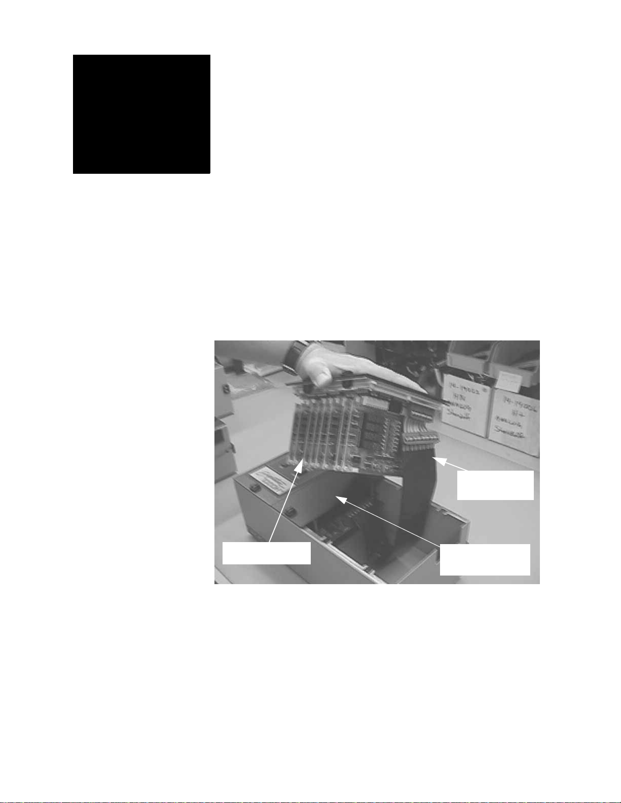
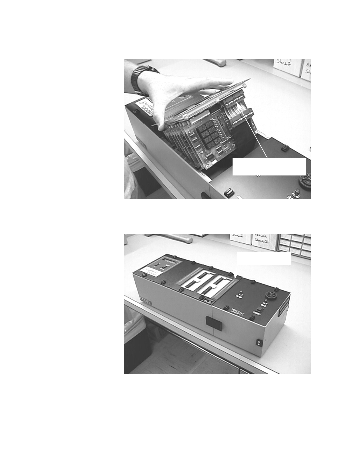
1. Open the quarter-turn fasteners, and remove the scanner cover plate, then
gently lift the scanner assembly out of the chassis of the 10000H+.
In this view, the quarter-turn fasteners which hold the scanner assembly
Scanner assembly
Ribbon Cable
(still connected)
Center Cover
Plate (still attached)
on the analyzer have been opened, and the cover plate has been
removed. The scanner assembly has been lifted from the chassis. Note
that the ribbon cable which connects the scanner with the rest of the
analyzer is still connected. The center cover plate is still in place on
the analyzer’s chassis.
Installation
Procedure

Installation Procedure 100
1000HX Alarm Box Add-On Tech. Note page 4
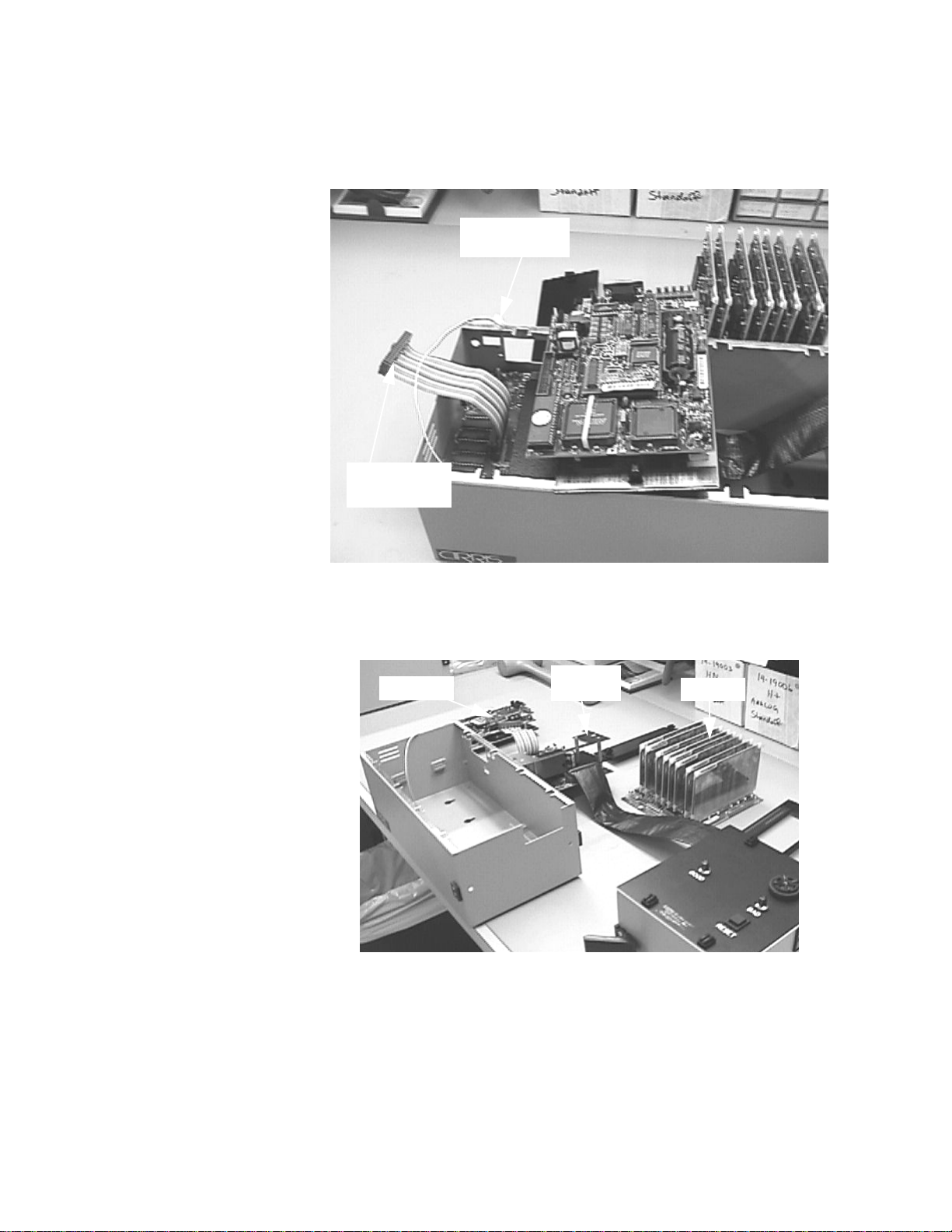
2. Disconnect the ribbon cable from the scanner assembly, set the scanner
assembly aside. Place the Alarm Box next to the 1000HX. Note: When you
latch the two boxes together shortly, the pins on the side of the Alarm Box will
fit into the holes in the side of the analyzer itself.
3. Remove the center cover plate from the 1000HX, and set the plate aside.
Ribbon cable
(now disconnected)
Scanner Assembly
Alarm Box
Scanner cover
plate
In this view, the Scanner Assembly has been disconnected, and
set aside lying on its top. The Scanner Cover Plate has also been
set aside.
In this view the Center Cover Plate has been removed
Center Cover Plate
removed

Installation Procedure 1000
1000HX Alarm Box Add-On Tech. Note page 5
4. Unlock the quarter-turn fasteners on the Processor Assembly, and lift it gently
from the chassis as shown. Be sure to gently remove the processor at an
angle as shown! This will avoid snapping the pogo pin that grounds the
processor to the chassis. Note the ribbon cable connected to the Processor.
5. Turn the Processor Assembly over gently. You’ll see the ribbon cable still
connected to it. The wires running to the system speaker are also still
connected.
Ribbon cable
Ribbon Cable
(still connected)
(still connected)
Speaker Wires
Installation Procedure 100
1000HX Alarm Box Add-On Tech. Note page 6
6. Disconnect both the ribbon cable and the speaker wires, and lay them carefully
aside. The Processor Assembly is now disconnected from the rest of the
analyzer.
7. Gently, lift the analog assembly up and out of the chassis. The chassis will now
be essentially empty.
Ribbon Cable
(disconnected)
Speaker Wires
(disconnected)
In this view, the Processor Assembly and the Scanner Assembly
have both been laid aside lying on their tops. The analog assembly
with its metal frame has been lifted out of the chassis, and set
on the bench.
Processor Analog
Assembly Scanner

Installation Procedure
1000HX Alarm Box Add-On Tech. Note page 7
8. Unlock the quarter-turn fasteners on the alarm box, and lift the top assembly
out of the chassis. Lay the assembly carefully on its top as shown. Note the
long ribbon cable coming from the upper assembly in the Alarm box.
9. Pop out the plastic covers from the rectangular openings in the sides of both
boxes (if they’re there), snake the long ribbon cable through the rectangular
openings in the sides of both chassis, then butt the two chassis together (the
pins on the side of the Alarm Box should fit into the holes in the side of the ana-
lyzer) and engage the drawlatches to lock the boxes together. Replace the top
assembly on the alarm box. Note that the long ribbon cable should snake across
the entire bottom of the analyzer’s chassis box.
Long Ribbon Cable
These openings
may have plastic
covers in them
Speaker Wires
(disconnected) Long Ribbon Cable

Installation Procedure 1
1000HX Alarm Box Add-On Tech. Note page 8
10. Replace the analog assembly (with its metal frame) in the analyzer’s chassis.
Note that the speaker wires and the long ribbon cable still aren’t connected. In
the lower photo (with the analog assembly in place), note how the long ribbon
cable and the speaker wires run down alongside the analog assembly.
Analog Assembly
Speaker Wires
Long ribbon cable
Wide Ribbon Cable
Center Cover Plate Scanner Assembly
Scanner Cover Plate
Speaker Wires and
Long Ribbon Cable
Analog-to-Processor
Cable (Wide Ribbon
Cable)

Installation Procedure 100
1000HX Alarm Box Add-On Tech. Note page 9
11. Connect the long ribbon cable, and the wide Analog-to-Processor ribbon cable
to the connectors on the processor as shown here.
12. Connect the speaker wire as shown here. By now, all three cables (the wide
Analog-to-Processor ribbon cable, the narrower long ribbon cable, and the
speaker wires should all be connected to the processor assembly. If they’re not
all connected as shown in this photo, connect them.
Long Ribbon Cable
connects here...
Wide Ribbon Cable
connects here.
Speaker Wires
Analog-to-Processor
wide ribbon cable
Narrow Ribbon
Cable
Installation Procedure 1
1000HX Alarm Box Add-On Tech. Note page 10
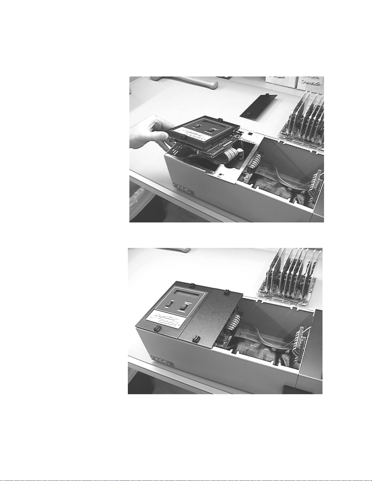
13. With all three cables reconnected to the processor assembly, turn the processor
assembly right side up, and carefully lower it back into the chassis as shown
here. Be sure to lower the assembly at an angle as shown! This will avoid
snapping the pogo pin that grounds the processor to the chassis.
14. Replace the center cover plate as shown here.
Installation Procedure 1
1000HX Alarm Box Add-On Tech. Note page 11
15. Reconnect the Processor-to-Scanner ribbon cable, then lower the scanner
assembly carefully back into the chassis as shown here.
16. Replace the scanner cover plate. The installation of the Alarm Box is now
complete!
Reconnect the Processor-to-
Scanner ribbon cable...
Replace the Scanner
Cover Plate

Installation Procedure
1000HX Alarm Box Add-On Tech. Note page 12
Table of contents
Other Cirris Measuring Instrument manuals


Popular Measuring Instrument manuals by other brands


sauermann
sauermann DBM 620 user manual

WAGO
WAGO 879-3000 4PU operating instructions

Shinwa
Shinwa Blue Level Pro 2 instruction manual

PCB Piezotronics
PCB Piezotronics IMI SENSORS 607M83 Installation and operating manual

Kusam-meco
Kusam-meco KM 907 Operation manual

Weidmüller
Weidmüller PTX800D quick start guide