manuals.online logo
Brands
  1. Home
  2. •
  3. Brands
  4. •
  5. Cisco
  6. •
  7. Gateway
  8. •
  9. Cisco S195 User manual

Cisco S195 User manual

Other manuals for S195

2

This manual suits for next models

3

Other Cisco Gateway manuals

Cisco 3G MicroCell User manual

Cisco

Cisco 3G MicroCell User manual

Cisco EPC2434 User manual

Cisco

Cisco EPC2434 User manual

Cisco Linksys WAG310G User manual

Cisco

Cisco Linksys WAG310G User manual

Cisco Catalyst 8200 Series User manual

Cisco

Cisco Catalyst 8200 Series User manual

Cisco VG450 Instruction Manual

Cisco

Cisco VG450 Instruction Manual

Cisco ASR 5000 Instruction Manual

Cisco

Cisco ASR 5000 Instruction Manual

Cisco VG400 series Manual

Cisco

Cisco VG400 series Manual

Cisco Small Business SPA8800 User manual

Cisco

Cisco Small Business SPA8800 User manual

Cisco DPC3949 User manual

Cisco

Cisco DPC3949 User manual

Cisco IOS XE Intelligent Services User manual

Cisco

Cisco IOS XE Intelligent Services User manual

Cisco WAG54G User manual

Cisco

Cisco WAG54G User manual

Cisco Explorer 4250 User manual

Cisco

Cisco Explorer 4250 User manual

Cisco VG410 Manual

Cisco

Cisco VG410 Manual

Cisco DPA 7610 Instruction Manual

Cisco

Cisco DPA 7610 Instruction Manual

Cisco REN301 User manual

Cisco

Cisco REN301 User manual

Cisco DPC2325 User manual

Cisco

Cisco DPC2325 User manual

Cisco EVM-IPVS-16A Quick start guide

Cisco

Cisco EVM-IPVS-16A Quick start guide

Cisco AudioCodes MP-1288 User manual

Cisco

Cisco AudioCodes MP-1288 User manual

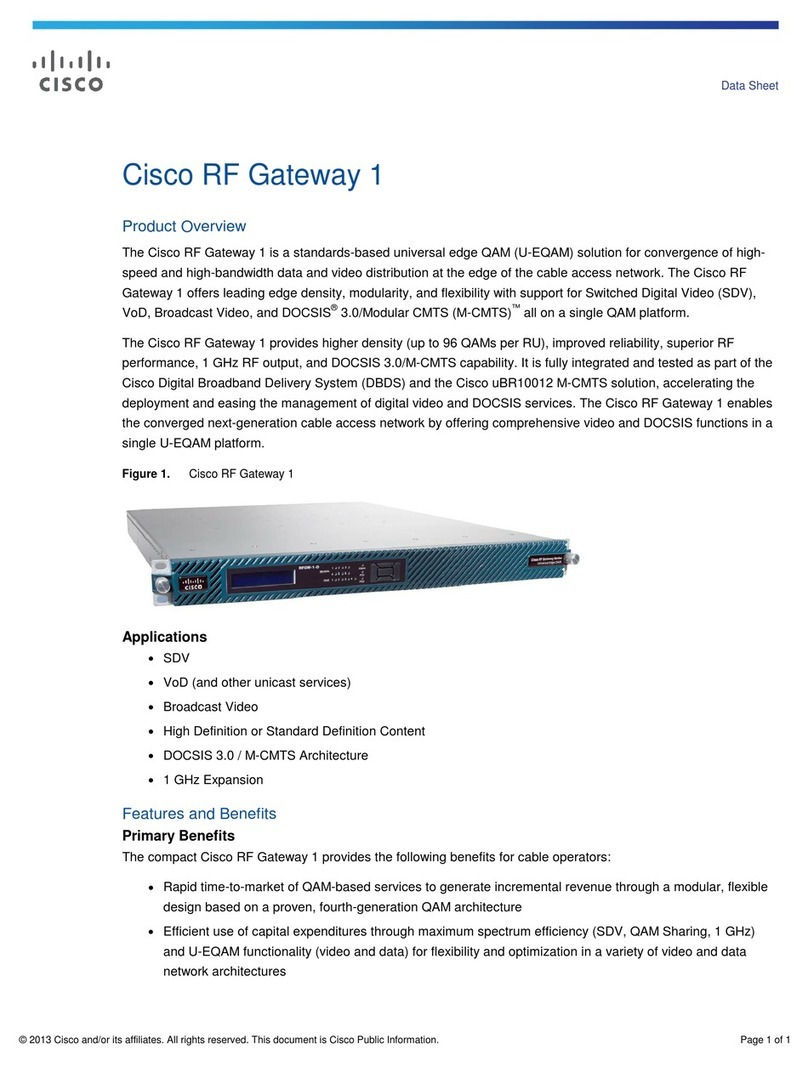
Cisco RF 1 User manual

Cisco

Cisco RF 1 User manual
Cisco Connected Life CLG-8202-WW User manual

Cisco

Cisco Connected Life CLG-8202-WW User manual

Cisco Linksys WAG54GX2 User manual

Cisco

Cisco Linksys WAG54GX2 User manual

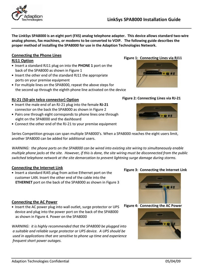
Cisco Linksys SPA8000-XU Original operating instructions

Cisco

Cisco Linksys SPA8000-XU Original operating instructions

Cisco DPR2320 Operating instructions

Cisco

Cisco DPR2320 Operating instructions

Cisco ASR 5000 Series Instruction Manual

Cisco

Cisco ASR 5000 Series Instruction Manual

Popular Gateway manuals by other brands

Telecom FM onestream gfx Programming guide

Telecom FM

Telecom FM onestream gfx Programming guide

UfiSpace LoRa GPE810U Quick setup guide

UfiSpace

UfiSpace LoRa GPE810U Quick setup guide

Merak MMk-736F Quick setup guide

Merak

Merak MMk-736F Quick setup guide

Robustel R3010 user guide

Robustel

Robustel R3010 user guide

turck BL20-PG-EN-V3 user manual

turck

turck BL20-PG-EN-V3 user manual

IBM Security Web Gateway Appliance quick start guide

IBM

IBM Security Web Gateway Appliance quick start guide

SSS Siedle Smart Gateway Commissioning instructions

SSS Siedle

SSS Siedle Smart Gateway Commissioning instructions

ADTRAN 424RG Installation

ADTRAN

ADTRAN 424RG Installation

Chorus Hyperfibre XGS-250WX-A user guide

Chorus

Chorus Hyperfibre XGS-250WX-A user guide

Dragino G308 user manual

Dragino

Dragino G308 user manual

Data Domain DD690g Installation and setup guide

Data Domain

Data Domain DD690g Installation and setup guide

Raritan Laptop Release notes

Raritan

Raritan Laptop Release notes

Haivision Torpedo quick start guide

Haivision

Haivision Torpedo quick start guide

ATCOM AG-268 user manual

ATCOM

ATCOM AG-268 user manual

LST M500RFE-AS Specification sheet

LST

LST M500RFE-AS Specification sheet

Vega VEGA BS-3 user manual

Vega

Vega VEGA BS-3 user manual

Kinnex Media Gateway quick start guide

Kinnex

Kinnex Media Gateway quick start guide

2N Telekomunikace 2N StarGate user manual

2N Telekomunikace

2N Telekomunikace 2N StarGate user manual

manuals.online logo
manuals.online logoBrands
  • About & Mission
  • Contact us
  • Privacy Policy
  • Terms and Conditions

Copyright 2025 Manuals.Online. All Rights Reserved.

Overview
•Features, on page 1
•Package Contents, on page 4
•Serial Number Locations, on page 5
•Front Panel, on page 5
•Front Panel LEDs, on page 9
•Rear Panel, on page 11
•Rear Panel LEDs, on page 14
•Power Supply, on page 15
•Hardware Specifications, on page 16
•Product ID Numbers, on page 17
•Power Cord Specifications, on page 17
Features
The Cisco Web Security Appliances (WSA) S195, S395, S695, and S695F help organizations secure and
control web traffic.
The WSA S195, S395, S695, and S695F support Cisco AsyncOS version 11.8 and later. See Product ID
Numbers, on page 17 for a list of field-replaceable product IDs (PIDs) associated with the WSA security
appliances.
The following figures show the Cisco Web Security appliances.
Figure 1: Cisco Web Security S195 and S395
Overview
1
Figure 2: Cisco Web Security S695 and S695F
The following table lists the features of the WSA S195, S395, S695, and S695F.
Table 1: WSA S195, S395, S695, and S695F Features
S695FS695S395S195Feature
2 RU1 RUForm factor
Standard 19-in. (48.3 cm) 4-post EIA rackRack mount
Front to rear
Cold aisle to hot aisle
Airflow
Displays the serial number.Pullout asset card
Two threaded holes for dual-hole grounding lug
Use is optional; the supported AC power supplies have internal grounding, so no
additional chassis grounding is required.
Grounding holes
OptionalLocking faceplate
On front panelUnit identification
button
On rear panelPower button
64-GB RAM32-GB RAM
16-GB RAMMemory
Four 16-GBTwo 16-GBOne 16-GBRDIMMs
Internal component
only; not
field-replaceable
One (M1)
M2 is not supported.
Management ports
Two (P1 and P2)Proxy ports
Two (T1 and T2)Traffic ports
Accessed through the 1-Gb dedicated portRemote power
cycling (RPC)
Two USB 3.0 Type AUSB ports
Overview
2
Overview
Features
S695FS695S395S195Feature
Six fiber optic
NoSFP+ ports
GLX-SX-MMD (1
Gb) (optional)
SFP-10G-SR
(10-Gb) (optional)
—Supported SFP+
One 1-Gb RJ45 serial port running RS-232 (RS-232D TIA-561)Serial console port
Two
1050 W AC
Hot-swappable and redundant as 1+1
Two
770 W AC
Hot-swappable and
redundant as 1+1
One
770 W AC
You can order a
second power
supply for
redundancy as 1+1.
AC power supply
Do not
mix
power
supply
type or
wattage
between
models.
Note
Six fans for front-to-rear cooling
Internal component only; not field-replaceable. If one fan fails, you must send your
chassis for RMA.
Fans
Sixteen 600-GB SAS HDDs
RAID 10, hot-swappable
Four 600-GB SAS
HDDs
RAID 10,
hot-swappable
Two 600-GB SAS
HDDs
RAID 1,
hot-swappable
Storage
Overview
3
Overview
Features
Package Contents
Figure 3: Package Contents
RJ-45 to DB9-RS232 console cable (Cisco part
number 72-3383-XX)
2Chassis1
RJ-45 to RJ-45 Cat 5 Ethernet cable, yellow six
feet long (Cisco part number 72-1482-XX)
4Cisco rail kit (Cisco part number 800-43376-02)3
Two 1-Gb or 10-Gb SFP+ fiber optic transceivers
with cables
Supported on the You cannot mix SFP
transceiver types in the same chassis.
You can either have two 1-Gb or two
10-Gb SFPs in the same chassis.
Note
6Useful Links document
The steps in the Useful Links document send you
to the documentation you need to install, set up,
and configure your appliance.
5
Overview
4
Overview
Package Contents
Serial Number Locations
Figure 4: Serial Number on Pullout Asset Card
The serial number is also on the label on the cover of the chassis as shown in the following figure.
Figure 5: Serial Number Location on Cover
Cover latch
Not supported
2Serial number label1
Front Panel
The following figure shows the front panel features and disk-drive configuration for the WSA S195. See Front
Panel LEDs, on page 9 for a description of the LEDs.
Overview
5
Overview
Serial Number Locations
Figure 6: S195 Front Panel
Power button/power status LED2Drive bays
Supports two 600-GB SAS HDDs in slots 1 and
2
1
System status LED4Unit identification button/LED3
Fan status LED6Power supply status LED5
Temperature status LED8Network link activity LED7
Pullout asset card9
The following figure shows the front panel features and disk-drive configuration for the WSA S395. See Front
Panel LEDs, on page 9 for a description of the LEDs.
Overview
6
Overview
Front Panel
Figure 7: S395 Front Panel
Power button/power status LED2Drive bays
Supports four 600-GB SAS HDDs in slots 1
through 4
1
System status LED4Unit identification button/LED3
Fan status LED6Power supply status LED5
Temperature status LED8Network link activity LED7
Pullout asset card9
The following figure shows the front panel features and disk-drive configuration for the WSA S695 and
S695F. See Front Panel LEDs, on page 9 for a description of the LEDs.
Overview
7
Overview
Front Panel
Figure 8: S695 and S695F Front Panel Features
Power button/power status LED2Drive bays
Supports sixteen 600-GB SAS HDDs in slots 1
through 16
1
System status LED4Unit identification button/LED3
Temperature status LED6Fan status LED5
Network link activity LED8Power supply status LED7
Pullout asset card9
Overview
8
Overview
Front Panel
Front Panel LEDs
Figure 9: Front Panel LEDs and Their States
Drive activity LED:
• Off—There is no drive in the drive tray (no
access, no fault).
• Green—The drive is ready.
• Green, flashing—The drive is reading or
writing data.
2Drive fault LED:
• Off—The drive is operating properly.
• Amber—Drive fault detected.
• Amber, flashing—The drive is rebuilding.
• Amber, flashing with 1-second
interval—Drive locate function activated in
the software.
1
Unit identification LED:
• Off—The unit identification function is not
in use.
• Blue, flashing—The unit identification
function is activated.
4Power LED:
• Off—There is no AC power to the chassis.
• Amber—The chassis is in standby mode.
• Green—The chassis is in main power mode.
Power is supplied to all components.
3
Overview
9
Overview
Front Panel LEDs
Power supply status LED:
• Green—All power supplies are operating
normally.
• Amber—One or more power supplies are in
a degraded operational state.
• Amber, flashing—One or more power
supplies are in a critical fault state.
6System status LED:
• Green—The chassis is running in normal
operating condition.
• Green, flashing—The chassis is performing
system initialization and memory check.
• Amber—The chassis is in a degraded
operational state (minor fault).
• Power supply redundancy is lost.
• CPUs are mismatched.
• At least one CPU is faulty.
• At least one DIMM is faulty.
• At least one drive in a RAID
configuration failed.
• Amber, 2 flashes—There is a major fault
with the system board.
• Amber, 3 flashes—There is a major fault
with the DIMMs.
• Amber, 4 flashes—There is a major fault
with the CPUs.
5
Network link activity LED:
• Off—The Ethernet port link is idle.
• Green—One or more Ethernet ports are
link-active, but there is no activity.
•Green, flashing—One or more Ethernet ports
are link-active with activity.
8Fan status LED:
• Green—All fans are operating properly.
• Amber, flashing—One or more fans
breached the nonrecoverable threshold.
7
Temperature status LED:
• Green—The chassis is operating at normal
temperature.
• Amber—One or more temperature sensors
breached the critical threshold.
• Amber, flashing—One or more temperature
sensors breached the nonrecoverable
threshold.
9
Overview
10
Overview
Front Panel LEDs