manuals.online logo
Brands
  1. Home
  2. •
  3. Brands
  4. •
  5. CLA-VAL
  6. •
  7. Control Unit
  8. •
  9. CLA-VAL 136-AU User manual

CLA-VAL 136-AU User manual

Model 136-AU Battery-Operated Programmable
Control Valve is ideal for automating distribution
system flushing applications. The valve is
installed in distribution system locations that
require a regular flushing schedule to maintain
system water quality within disinfection and
health standard limits. The valve vents a small
quantity of water for a short time on a regular
schedule to create desired water turnover.
Other Model 136-AU applications requiring
remote, stand alone valve opening and closing
on a predetermined schedule include night-time
tank filling, service line limiting time of use, auto-
matic line strainer flushing, etc.
Low usage
distribution line
Discharge to
storm drain or
atmosphere
Cla-Val 136-AU
Solenoid
Flush Valve
Optional
Flowmeter
Isolation
Valve Optional
Backflow Preventor
136-AU
MODEL
Battery-Powered
Programmable Control Valve
•Self-Contained, Battery-Powered
•Easily Programmed
•Waterproof Rugged Components
•Reliable Drip-Tight Shut-Off
•Easy Installation and Maintenance
The Cla-Val Model 136-AU Battery-Operated Programmable Control Valve
provides on-off control of water flow according to a program sequence
without any outside power or remote control device required. The completely
self-contained 136-AU consists of a Hytrol main valve and 97VC-4
Programmable Solenoid Controller Unit that alternately applies pressure to
or relieves pressure from the diaphragm chamber of the main valve to
close or open it. An adjustable speed control is supplied for closing rate
adjustment and surge control.
The 97VC-4 Programmable Solenoid Controller Unit contains controller with
display, solenoid, actuator, and battery. The 97VC-4 uses the latest technolo-
gy for easy and flexible programming of desired opening and closing sched-
ule according to time of day, day of week, and month. The controller clock
includes leap year. With normal use, the factory installed lithium battery will
operate the 136-AU for up to 10 years. Manual override of program is eas-
ily accomplished. It has a LCD display to show clock and programming set-
tings. The 97VC-4 has a waterproof design that is submersible to NEMA 6P
standard.
Schematic Diagram
Item Description
1 Hytrol (Main Valve)
2 97VC-4 Controller and Solenoid
3 Closing Speed Control
Optional Features
Item Description
A X46A Flow Clean Strainer
B CK2 (Isolation Valve)
Y X43 "Y" Strainer
Typical Applications
(Full Internal Port)
97VC-4 Programmable Solenoid Controller
Features
• Manual On or Off override at any time
• On time range from 1 minute to 12 hours
• Waterproof LCD display of programming
• Up to 6 different programs can be scheduled
• Flexible Day and Week scheduling
• Single Lithium Battery, Long-Life
• Low-power latching type solenoid
• Up to 10 year service with one battery
• Protective cover included
136-AU PURCHASE SPECIFICATIONS
The Battery-Operated Control Valve shall consist of an on-
off control valve, which opens or closes upon receiving
hydraulic signals from attached programmable controller
that contains an integral latching, battery-powered sole-
noid valve. The control valve shall be diaphragm actuated
and fully guided using an integral bearing in the seat and
cover. The programmable controller shall be waterproof to
NEMA 6P and initiate all on or off operation sequences of
the main control valve by the activation of the latching
solenoid. All electrical power for controller and solenoid
shall be from a single 3.6 Volt Lithium Battery contained in
the controller housing.
Two dials and plus and minus toggle buttons shall be pro-
vided on the top of the controller along with LCD type dis-
play under a removable protective cover and shall allow
easy programming of the controller and valve sequence.
The controller shall allow the user to set the current time,
date, and year.
Six programming choices shall provide valve actuation for
every day of the week, and for true odd/even or 1-30 day
intervals. Valve actuation shall be programmed to begin
on the minute and run one minute to 12 hours in duration.
The controller shall provide a means of manually overriding
the programmed schedule with a timed 10 minute default
ON operation and a dedicated OFF function.
The Battery-Operated Control Valve shall be similar in all
respects to the Model 136-AU as manufactured by Cla-Val
Company, Newport Beach, California.
97VC-4 OPERATION AND PROGRAMMING
The 97VC-4 Programmable Controller uses the latest
technology and will provide many years of reliable service.
Please follow these instructions for programming and gen-
eral operation information on the 97VC-4 and 136-AU.
PROTECTIVE COVER
To remove protective cover, squeeze the side tables and
lift. Always replace the cover for added protection of the
LCD display and control buttons.
SETTING THE CLOCK (refer to drawing)
SET THE TIME OF DAY
Turn the Select dial to the TIME position. Press the + or -
keys to scroll to the correct time. There is a P on the dis-
play to indicate PM.
SET TODAY’S DATE
Turn the Select dial to the DATE position. Press the + or -
keys to scroll to the correct date.
SET THE YEAR
Turn the Select dial to the YEAR position. Press the + or -
keys to scroll to the correct year. When DATE and YEAR
are selected the day of the week is automatically set. The
97VC-4 is leap year compatible.
CHANGING CLOCK DISPLAY FORMATS
Default TIME display format is 12 hour clock with
Month:Day format. If desired, the display can be changed
to 24 hour and Day:Month format after initial setting.
Rotate Select dial to the TIME or DATE position. Press
the + and - keys at the same time to change the clock for-
mat. If in 12 hour format, the PM indicator will disappear
and the clock will change to 24 hour time and the date dis-
play will change to Day:Month format. Days of the week
will change from SMTWTFS to 1234567 (Sunday = 1).
To change display back to 12 hour clock and Month:Day
format repeat the above steps.
SETTING A VALVE SCHEDULE
The 97VC-4 Controller can be programmed to run 1 to 6
programs per day. This means that you can open and
close the 136-AU valve from 1 to 6 times in a 24 hour peri-
od.
SET TIME SCHEDULE
Begin setting desired valve schedule by starting with
Program 1. Turn Select dial to PROGRAM 1 position.
SET START TIME
Turn the Set dial to START TIME. Press the + or - keys to
scroll to the desired START TIME for PROGRAM 1.
SET STOP TIME
Turn the Set dial to STOP TIME. Press the + or - keys to
scroll to the desired STOP TIME for PROGRAM 1.
Select
Dial
Set
Dial
PM Indicator
Low Battery
Symbol
+
-
SMT WT SF
P
RUN
RUN
ALL
TIME
DATE
YEAR
CLEAR
RAIN
DELAY
INTERVAL
ODD
EVEN
DAYS
TIME
START
TIME
OFF
Open
STOP
1
2
3
4
5
6
Manual
P
r
o
g
r
a
m
SET DAY SCHEDULE
For each program, you can select either: DAYS (specific
days of week), ODD/EVEN (every other days), or INTERVAL
(fixed number of days apart) that PROGRAM 1 will be acti-
vated starting with today. The display will change to show
day schedule selected.
SET DAYS
Turn the Set dial to DAYS position. Press the + or - keys
to scroll to the desired days you want valve to operate for
PROGRAM 1. The + key will select that day and the - key
will delete that day from the list of days on the display.
SET ODD/EVEN DAYS
Turn the Set dial to ODD/EVEN position. Press the + or -
keys to select O or E days you want valve to operate for
PROGRAM 1.
SET INTERVAL DAYS
Turn the Set dial to INTERVAL position. Press the + or -
keys to select an interval from 01 to 30 days starting today
you want that valve to operate for PROGRAM 1.
Example: An interval of 01 causes valve to operate
PROGRAM 1 every day and an interval of 02 causes
valve to operate PROGRAM 1 every other day.
SET ADDITIONAL PROGRAMS
If more that one program (valve open-close) per day is
desired, turn the Select dial to PROGRAM 2,3,4,5 or 6
and repeat the SET TIME and SET DAY schedule steps
above. If no additional program schedules are needed,
then proceed to next step.
RUNNING YOUR 97VC-4 SCHEDULE
You can choose to run all six programs or select any one
of the six. Turn the Select Dial to your choice of RUN ALL
to run all six programs that have been entered or select
the individual PROGRAM number 1-6 that you wish to run.
Turn the Set Dial to the RUN position. The 136-AU will
operate (open and close) according to the program or pro-
grams you have selected.
REVIEW AND CHANGING YOUR 97VC-4 SCHEDULE
You can review or change the schedule you have on the
97VC-4 at any time. Turn the Select dial to any one of the
six programs. Use the Set Dial to select one position of
START TIME, STOP TIME, DAYS, Interval, or ODD/EVEN.
Press the + or - keys to select a new value for the select-
ed program.
TURNING OFF THE 136-AU VALVE
To close the valve while it is in operation or to prevent
automatic operation turn Set Dial to the OFF position. To
return to automatic operation return Set Dial to the RUN
position.
MANUAL OPERATION OF THE 136-AU VALVE
Manually override the automatic schedule in the 97VC-4
by turning the Set Dial to the MANUAL OPEN position.
The LCD display will flash 10 minutes of valve open time.
There is a 30 second delay to open or close the valve.
You can adjust the desired valve open time from 1 minute
to 6 hours by using the + or - keys at any time during the
manual valve open time.
To return to automatic schedule, turn the Set Dial to RUN
after the manual valve open time has started. Once the
valve completes the manual valve open time, the 97VC-4
will close the valve and return to automatic operation
schedule.
To stop manual valve open time, rotate Set Dial to the
OFF position. To return to automatic operation schedule
rotate Set Dial to the RUN position.
CLEARING YOUR 97VC-4 SCHEDULE
To clear the values in one of the six programs, first turn
the Select Dial to PROGRAM 1, 2, 3, 4, 5, or 6 position
and turn the Set Dial to CLEAR and press the - key.
To clear the values in all of the six programs, first, turn the
Select Dial to RUN ALL position, turn the Set Dial to
CLEAR and press both the + and the - key at the same
time. This will clear all programs.
97VC-4 MAINTENANCE
Battery Replacement
The long life 3.6 volt size AA Lithium battery is replaceable
when necessary. Remove two screws under control hous-
ing and gently open the unit. Replace the battery.
Carefully replace housing and install the two screws.
PLUNGER CLEANING
If valve fails to operate debris may need to be cleaned from
the 97VC-4 plunger area. By hand, rotate programmer and
plunger assembly clockwise to loosen. Gently remove it
from valve port. Remove any visible debris. To clean the
plunger and plunger tube at the bottom of the 97VC-4, gently
remove the plastic plunger retainer with needle-nosed pliers.
Carefully clean debris from plunger and plunger tube. Avoid
damage when replacing plunger retainer, plunger tube,
plunger, and programmer assembly.
LCD DISPLAY
If LCD display is not working or the battery symbol is
flashing, the battery must be replaced.
See 136-AU IOM Technical Manual for service
and maintenance instructions on other valve components.
Model 136-AU Dimensions (In Inches) Valve Size (Inches) 22 1⁄23 4
AThreaded 9.38 11.00 12.50 —
AA 150 ANSI 9.38 11.00 12.00 15.00
AAA 300 ANSI 10.00 11.62 13.25 15.62
B Dia. 6.62 8.00 9.12 11.50
CMax. 6.50 7.56 8.19 10.62
D Threaded 4.75 5.50 6.25 —
DD 150 ANSI 4.75 5.50 6.00 7.50
DDD 300 ANSI 5.00 5.88 6.38 7.88
E1.50 1.69 2.56 3.19
F150 ANSI 3.00 3.50 3.75 4.50
FF 300 ANSI 3.25 3.75 4.13 5.00
GThreaded 3.25 4.00 4.50 —
GG 150 ANSI 3.25 4.00 4.00 5.00
GGG 300 ANSI 3.50 4.31 4.38 5.31
HNPT Body Tapping 3⁄81⁄21⁄23⁄4
JNPT Cover Center Plug 1⁄21⁄21⁄23⁄4
KNPT Cover Tapping 3⁄81⁄21⁄23⁄4
Valve Stem Internal
Thread UNF 10-32 10-32 1⁄4-28 1⁄4-28
Stem Travel 0.6 0.7 0.8 1.1
Approx. Ship Wt. Lbs. 35 50 70 140
X Pilot System 13.00 14.00 15.00 17.00
YPilot System 9.00 10.00 11.00 12.00
Z Pilot System 9.00 10.00 11.00 12.00
Sizes:
Globe: 2" - 3" threaded 2" - 4" flanged
Angle: 2" - 3" threaded, 2" - 4" flanged
End details:
Flanged: 150 and 300 ANSI B 16.1
Threaded: 300 ANSI B 2.1
Temperature Range
Water: from 32°F to 140°F
Materials:
Main valve body and cover:
Ductile Iron ASTM A536
Epoxy coated inside and outside standard
Main valve trim:
Brass QQ-B-626
Bronze ASTM B-61
Optional: Stainless Steel 303
Stem: Stainless Steel 303
97VC-4 Programmable Controller
32 to 120 degrees Fahrenheit
Operating Pressure 7 to 150 psi
NEMA 6P waterproof
Single Lithium Battery, AA size, 3.6 volt
Pilot Control System: Bronze and Copper
Optional: Stainless Steel
When Ordering, Please Specify
1. Catalog No. 136-AU
2. Valve Size
3. Pattern - Globe or Angle
4. Pressure Class
5. Threaded or Flanged Ends
6. Main Valve Materials Desired
7. Desired Pilot System Options
Specifications
PO Box 1325 Newport Beach CA 92659-0325
Phone: 949-722-4800 Fax: 949-548-5441
CLA-VAL
CLA-VAL CANADA CLA-VAL EUROPE
4687 Christie Drive
Beamsville, Ontario
Canada LOR 1B4
Phone: 905-563-4963
Fax: 905-563-4040
Chemin dés Mesanges 1
CH-1032 Romanel/
Lausanne, Switzerland
Phone: 41-21-643-15-55
Fax: 41-21-643-15-50
©COPYRIGHT CLA-VAL 2005 Printed in USA
Specifications subject to change without notice. www.cla-val.com
E-136-AU
Represented By:
For 100-01 basic valves, suggested
flow calculations were based on flow
through Schedule 40 Pipe. Maximum
continuous flow is approx. 20 ft/sec
(6.1 meters/sec) & maximum intermit-
tent is approx. 25ft/sec (7.6
meters/sec).
Valve Selection
These Symbols A and B Indicate Available Sizes
Inches 2 21⁄23 4
mm 50 65 80 100
End Detail Threaded Threaded or Flanged
Model
136-AU
Basic Valve
100-01
Globe A A A A
Angle B B B B
Suggested Flow
(gpm)
Max. Continuous 210 300 460 800
Max. Intermittent 260 370 580 990
Suggested Flow
(Liters/Sec)
Max. Continuous 13 19 29 50
Max. Intermittent 16.4 23 37 62
100-01 (Globe)
B
100-01 (Angle)

Other CLA-VAL Control Unit manuals

CLA-VAL 49-01 Installation and operating instructions

CLA-VAL

CLA-VAL 49-01 Installation and operating instructions

CLA-VAL 49-01/649-01 General instructions

CLA-VAL

CLA-VAL 49-01/649-01 General instructions

CLA-VAL 81-02 User manual

CLA-VAL

CLA-VAL 81-02 User manual

CLA-VAL 50B-4KG1 Installation and operating instructions

CLA-VAL

CLA-VAL 50B-4KG1 Installation and operating instructions

CLA-VAL 340-07 General instructions

CLA-VAL

CLA-VAL 340-07 General instructions

CLA-VAL CPC 138-01 Guide

CLA-VAL

CLA-VAL CPC 138-01 Guide

CLA-VAL 600 Series Owner's manual

CLA-VAL

CLA-VAL 600 Series Owner's manual

CLA-VAL 50B-5KG Owner's manual

CLA-VAL

CLA-VAL 50B-5KG Owner's manual

CLA-VAL 50B-4KG1 Owner's manual

CLA-VAL

CLA-VAL 50B-4KG1 Owner's manual

CLA-VAL 60-73 User manual

CLA-VAL

CLA-VAL 60-73 User manual

CLA-VAL 81-01 Owner's manual

CLA-VAL

CLA-VAL 81-01 Owner's manual

CLA-VAL 750B-4KG1 Owner's manual

CLA-VAL

CLA-VAL 750B-4KG1 Owner's manual

CLA-VAL 90-48 Owner's manual

CLA-VAL

CLA-VAL 90-48 Owner's manual

CLA-VAL CRL-60 Owner's manual

CLA-VAL

CLA-VAL CRL-60 Owner's manual

CLA-VAL CRL-60 Owner's manual

CLA-VAL

CLA-VAL CRL-60 Owner's manual

CLA-VAL 50B-5KG Installation and operating instructions

CLA-VAL

CLA-VAL 50B-5KG Installation and operating instructions

CLA-VAL 631-73 Owner's manual

CLA-VAL

CLA-VAL 631-73 Owner's manual

CLA-VAL 131-01 General instructions

CLA-VAL

CLA-VAL 131-01 General instructions

CLA-VAL CRL Installation and operating instructions

CLA-VAL

CLA-VAL CRL Installation and operating instructions

CLA-VAL 93-01 Owner's manual

CLA-VAL

CLA-VAL 93-01 Owner's manual

CLA-VAL 90-21 Owner's manual

CLA-VAL

CLA-VAL 90-21 Owner's manual

CLA-VAL 90-21 Owner's manual

CLA-VAL

CLA-VAL 90-21 Owner's manual

CLA-VAL 92-01 Owner's manual

CLA-VAL

CLA-VAL 92-01 Owner's manual

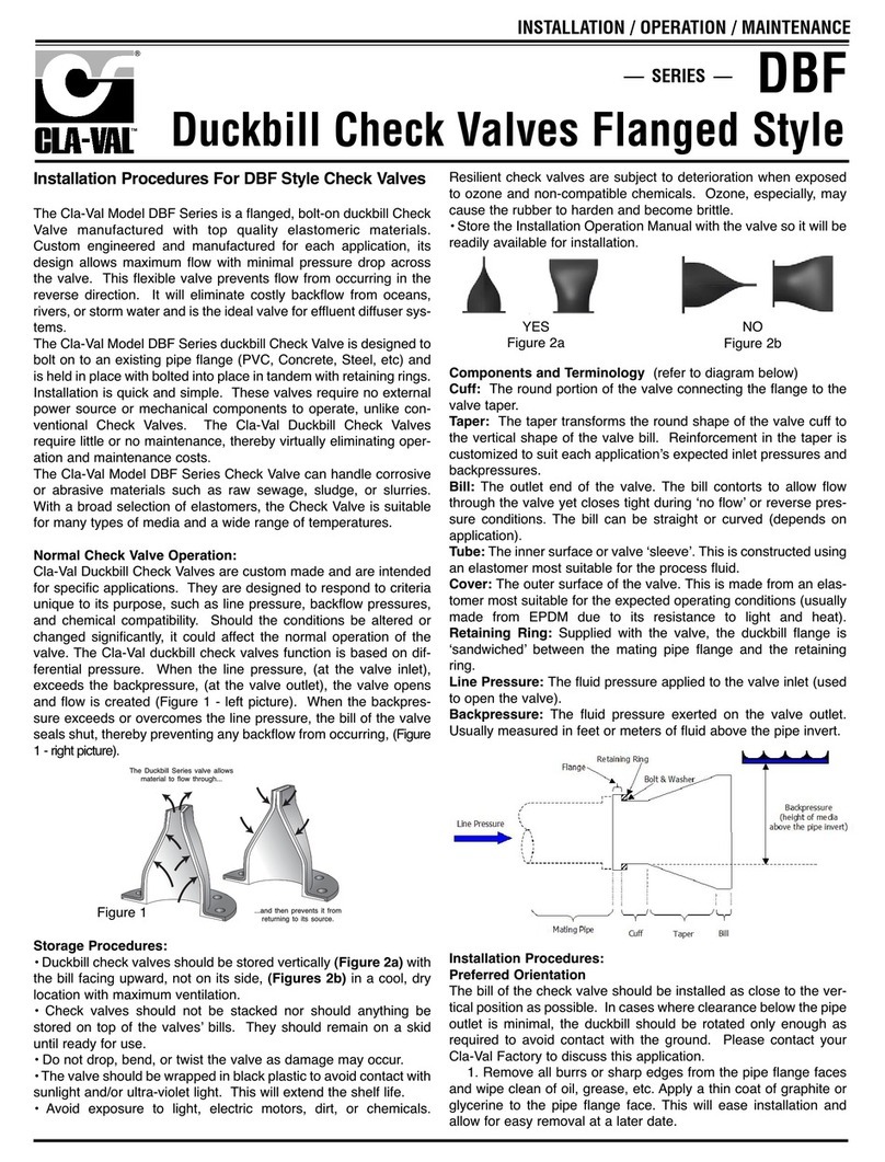
CLA-VAL DBF Series Owner's manual

CLA-VAL

CLA-VAL DBF Series Owner's manual

Popular Control Unit manuals by other brands

LiteOn WN4629R user manual

LiteOn

LiteOn WN4629R user manual

Texas Instruments bq2060AEVM-001 user guide

Texas Instruments

Texas Instruments bq2060AEVM-001 user guide

MKS Automated SENTRY 1000-300 Installation and operation manual

MKS

MKS Automated SENTRY 1000-300 Installation and operation manual

Geco G-403-P04 Service & operating instructions

Geco

Geco G-403-P04 Service & operating instructions

PPM ViaLiteHD HRx-C-HB-1 series user guide

PPM

PPM ViaLiteHD HRx-C-HB-1 series user guide

Hisense HL3215STG manual

Hisense

Hisense HL3215STG manual

Texas Instruments TPSM846C23 user guide

Texas Instruments

Texas Instruments TPSM846C23 user guide

CEBEK I-55 Information sheet

CEBEK

CEBEK I-55 Information sheet

Doepke Dupline DRO 4b operating instructions

Doepke

Doepke Dupline DRO 4b operating instructions

Comelit Simplebus Color 5714C Technical manual

Comelit

Comelit Simplebus Color 5714C Technical manual

REXROTH IndraControl L40 Series Project planning manual

REXROTH

REXROTH IndraControl L40 Series Project planning manual

Festo MSE6-C2M manual

Festo

Festo MSE6-C2M manual

Bradley Equa-Flo S59-1005SR Installation

Bradley

Bradley Equa-Flo S59-1005SR Installation

Alcatel-Lucent 5620 troubleshooting guide

Alcatel-Lucent

Alcatel-Lucent 5620 troubleshooting guide

BROEN BALLOMAX Technical manual

BROEN

BROEN BALLOMAX Technical manual

SMC Networks VM400 Series Operation manual

SMC Networks

SMC Networks VM400 Series Operation manual

Sierra Wireless AirPrime HL8518 Product Technical Specification

Sierra Wireless

Sierra Wireless AirPrime HL8518 Product Technical Specification

Zamel EXTA EDM-01 instruction manual

Zamel

Zamel EXTA EDM-01 instruction manual

manuals.online logo
manuals.online logoBrands
  • About & Mission
  • Contact us
  • Privacy Policy
  • Terms and Conditions

Copyright 2025 Manuals.Online. All Rights Reserved.