manuals.online logo
Brands
  1. Home
  2. •
  3. Brands
  4. •
  5. CLA-VAL
  6. •
  7. Control Unit
  8. •
  9. CLA-VAL 36 Series Instruction manual

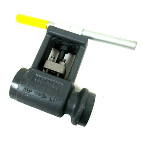
CLA-VAL 36 Series Instruction manual

Combination Air Valves
(Single Body Type)
Detail No.
1
2
3
4
5
6
7
8
9
10
11
12
13
14
15
16
17
18
29
30
34
Part Name
Body
Cover
Baffle
Seat
Float
Gasket
Cover Bolt
Retaining Screw
Guide Bushing
Float Arm
Orifice Button
Pivot Pin
Retaining Ring
Pipe Plug
Cushion
Plug
Float Retainer
Lock ut
Cushion Retainer
Washer (internal)
Washer (external)
INTRODUCTION
This manual will provide you with the information to properly
install and maintain this valve to ensure a long service life. The
valve has been designed with stainless steel trim to give years of
trouble-free operation. The Combination Air Valve is typically
mounted at the high points in a piping system and performs the
functions of both an air release valve and air/vacuum valve.
The Combination Air Valve automatically vents air which accu-
mulates at high points in a system during its operation. The valve
will also exhaust and admit large quantities (volumes) of air dur-
ing filling or draining operations and after emergency conditions
such as a power failure. Both the air release and air/vacuum
functions are needed to maintain pipeline efficiency while provid-
ing protection from adverse pressure conditions.
The valve is a float-operated, resilient-seated valve designed to
handle fluids having minimal suspended solids. The Maximum
Working Pressure and Model o. are stamped on the nameplate
for reference.
RECEIVING AND STORAGE
Inspect valves upon receipt for damage in shipment. Handle all
valves carefully without dropping. Valves should remain boxed,
clean and dry until installed to prevent weather related damage.
For long term storage greater than six months, the valves must
remain in the box and stored indoors. Do not expose valves to
sunlight or ozone for any extended periods.
DESCRIPTION OF OPERATION
The Combination Air Valve is fully automatic and designed to
continuously remove air accumulating at high points in a piping
system. It also will exhaust and admit air during filing and drain-
ing of the pipeline or tank. The valve, as shipped, is a normally
open valve and has three functions.
During System start-up, the open valve will exhaust large
quantities of air until fluid enters the valve. The float will then
rise and press the orifice button located in the float arm,
against the plug stem and raise the plug. Pressure within the
valve body will force the plug upward tightly against the seat.
When system is drained the plug will open allowing air to
reenter the system.
1.
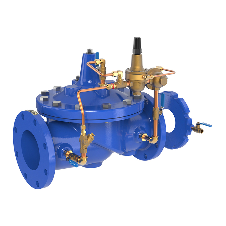
Figure 1. Custom Combination Air Valve
Figure 2.
Air Exhausted and Air
Intake During Pipeline
Fill and Drain.
As air accumulates in the piping system and enters the
valve, the float drops and the orifice button breaks contact
with the plug stem. Accumulated air will vent through the
plug stem. As the air is vented, the float raises once again
and closes the plug stem orifice. See Figure 2.
2.
INLET
Figure 3.
Accumulated Air
Continuously
Released
INLET
INSTALLATION / OPERATION / MAINTENANCE
Series 36
9
7
2
6
4
16
3
9
12
13
10
18
5
15
1
WORKING PRESSURE - 300 P.S.I.
TEST PRESSURE - 450 P.S.I.
14
8
11
17
29
30
34
18
14
FOR ILLUSTRATION ONLY
SPOKE SHOWN 90…
FROM ACTUAL ANGLE
34
Sizes 1” - 4” Threaded Inlet
Page 2
When the system is drained, the plug will reopen allowing air
to rapidly re-enter the piping system. See Figure 2.
3.
Sizes 6” & 8” Flanged Parts List
INSTALLATION
The installation of the valve is important for its proper operation.
Valves must be installed at the system high points in the vertical
position with the inlet down. For pipeline service, a vault with
freeze protection, adequate screened venting, and drainage
should be provided. During closure, some fluid discharge will
occur so vent lines should extended to an open drain area in
plant services. A shut-off valve should be installed below the
valve in the event servicing is required.
CAUTION: Always Install valve with “I LET” port
down or flooding will occur.
MAINTENANCE
The Combination Air Valve requires no scheduled lubrication or
maintenance.
I SPECTIO : Periodic inspection to verify operation can be per-
formed. A manual drain valve can be installed in the lower drain
plug to plug to perform this operation as shown in Figure 7.
DRAIN
VALVES
INLET SHUT-OFF
VALVE
FIGURE 5. I SPECTIO PIPI G
With the inlet shut-off valve open, partially open the drain
valve until flow can be heard. If the air valve is working prop-
erly, water should be exhausted from the drain valve. If air
is exhausted, follow steps 2-6.
1.
Close the inlet shut-off valve.
2.
Slowly open the drain valve to allow the fluid in the valve to
drain. If draining is difficult, the valve may be clogged (valve
requires service).
3.
Close the drain valve
4.
Slowly open the inlet shut-off valve to fill the valve with water.
Observe the seating action and verify that the valve closes
without leakage.
5.
If leakage occurs, the valve should be removed and inspect-
ed for water or possible damage from foreign matter.
6.
23
24
25
9
4
26
2
6
8
5
1
15
28
9
19 21
30 8A
4A
28
11
7
12
22
34
18
3
13
17
10
5A
INLET
OUTLET
125 LB. FLG.
or
250 LB. FLG.
Detail No.
1
2
3
4
4a
5
5a
6
7
8
8a
9
10
11
Detail No.
12
13
15
17
18
19
21
22
23
24
25
26
28
30
34
Part Name
Body
Cover
Leverage Frame
Seat
Seat
Float
Float
Gasket
Cover Bolt
Retaining Screw
Retaining Screw
Guide Bushing
Float Arm
Orifice Button
Part Name
Pivot Pin
Retaining Ring
Cushion
Float Retainer
Lock ut
Link
Locating Pin
Orifice Button Arm
Hood
Hood Retaining Screw
Washer - External
Seat Retaining Sleeve
Pipe Plug
Washer
Lock Washer
Adjust orifice button so that when it is in light contact with the
plug stem, the arm (10) slopes away from the cover about
1/15”. Lock orifice button with lock nut (18).
5.
Install new cushion (15) with fastener items (29, 30, 34, &
18).
6.
Lay new cover gasket on clean surface and apply a gasket
compound such as Permatex #80065 to both surfaces.
Assemble gasket (6) and cover (2) over bolt holes in body
(1).
7.
Insert lubricated bolts (7) and tighten to the torques listed in
Table 2.
8.
Place valve back in service. Slowly open inlet isolation valve.
9.
BOLT SIZE
7/16”-14
1/2”-13
5/8”-11
3/4”-10
7/8”-9
TORQUE (FT. LBS.)
30
45
93
150
200
TABLE 2. VALVE COVER BOLT TORQUES
PARTS AND SERVICE
Parts and service are available from your local representative or
the factory. Make note of the valve Model o. and Working
Pressure located on the valve nameplate.
TROUBLESHOOTING
Several problems and solutions are presented below to assist
you in troubleshooting the valve assembly in efficient manner
Lea age at Bottom Connection:
Tighten valve threaded connection. If leaks persist, remove valve
and seals threads with pipe sealant or tape.
Lea age at Cover:
Tighten bolts per Table 2, replace gasket.
Valve Lea s when Closed:
Flush valve to remove debris. Disassemble and inspect seat, ori-
fice button and float. OTE: Many floats contain sand for weight
but if water is detected replace float.
Valve not venting Air:
Check that operating pressure does not exceed Working
Pressure on nameplate. Perform inspection steps 2-6 and dis-
assemble valve if problem persists.
DISASSEMBLY
The valve can be disassembled without removing it from the
pipeline. Or for convenience, the valve can be removed from the
line. All work on the valve should be performed by a skilled
mechanic with proper tools. o special tools are required.
CAUTION: The valve must be drained before removing the
cover or pressure may be released causing injury.
Close inlet shut-off valve. Slowly open drain valve or remove
drain plug. Remove the covers bolts (7) on the top cover.
1.
Pry cover (2) loose and lift off valve body.
2.
Remove the retainer ring (13) and pivot pin (12) that pass
through the float arm (10).
3.
To remove baffle (3), remove fasteners (8).
4.
Remove lock nut (18) and orifice button (11).
5.
Clean and inspect parts. ote: some floats contain sand for
extra weight; if water is detected, replace float. Replace
worn parts as necessary and lubricate parts with FDA grease
such as Lubriko #Cw-606. Remove all foreign matter from
body and cover.
6.
REASSEMBLY
All parts must be cleaned and gaskets surfaces should be
cleaned with a stiff wire brush in the direction of the serration or
machine marks. Worn parts, gaskets and seal should be
replaced during reassembly. Refer to Figure 6.
Apply Loctite Primer and 680 Compound to float threads and
assemble to arm (10). Apply Loctite to bushing (9) and install
into baffle (3).
1.
Lay cover on flat surface with outlet faced down. Lay seat
(4), plug (16), and baffle (3) over cover with screws (8) loose-
ly engaged. Verify that plug moves up and down freely. Lift
plug and drop into seat until baffle is positioned and plug
contacts seat smoothly; tighten screws to 5-10 ft. lbs.
2.
Screw new orifice button (11) into arm (10) with lock washer
(34) and lock nut (18). Do not tighten nut at this time.
3.
Connect arm (10) to baffle (3) with pivot pin (12) and retain-
ing rings (13).
4.
Page 3
CLA-VAL
1701 Placentia Ave •Costa Mesa CA 92627 •Phone: 949-722-4800 •Fax: 949-548-5441 •E-mail: [email protected] •www.cla-val.com
Copyright Cla-Val 2018
•
Printed in USA
•
Specifications subject to change without notice.
©
-36 Series Single Body (R-01/2018)

Other CLA-VAL Control Unit manuals

CLA-VAL 43-01/643-01 User manual

CLA-VAL

CLA-VAL 43-01/643-01 User manual

CLA-VAL 40-01/640-01 Installation and operating instructions

CLA-VAL

CLA-VAL 40-01/640-01 Installation and operating instructions

CLA-VAL 90-01 Owner's manual

CLA-VAL

CLA-VAL 90-01 Owner's manual

CLA-VAL 50-01 Installation and operating instructions

CLA-VAL

CLA-VAL 50-01 Installation and operating instructions

CLA-VAL 636-03 Owner's manual
CLA-VAL

CLA-VAL 636-03 Owner's manual

CLA-VAL CRL-60 Owner's manual

CLA-VAL

CLA-VAL CRL-60 Owner's manual

CLA-VAL 90-01 Owner's manual

CLA-VAL

CLA-VAL 90-01 Owner's manual

CLA-VAL 55L-60 Owner's manual

CLA-VAL

CLA-VAL 55L-60 Owner's manual

CLA-VAL 50B-4KG1 Owner's manual

CLA-VAL

CLA-VAL 50B-4KG1 Owner's manual

CLA-VAL DBF Series Owner's manual

CLA-VAL

CLA-VAL DBF Series Owner's manual

CLA-VAL 98-06 Instruction manual

CLA-VAL

CLA-VAL 98-06 Instruction manual

CLA-VAL 49-01 Installation and operating instructions

CLA-VAL

CLA-VAL 49-01 Installation and operating instructions

CLA-VAL 90-48 Owner's manual

CLA-VAL

CLA-VAL 90-48 Owner's manual

CLA-VAL 131-01 General instructions

CLA-VAL

CLA-VAL 131-01 General instructions

CLA-VAL 600 Series Owner's manual

CLA-VAL

CLA-VAL 600 Series Owner's manual

CLA-VAL 34AR Series User manual

CLA-VAL

CLA-VAL 34AR Series User manual

CLA-VAL 790-01 Owner's manual

CLA-VAL

CLA-VAL 790-01 Owner's manual

CLA-VAL RP-2 User manual

CLA-VAL

CLA-VAL RP-2 User manual

CLA-VAL 92-07 Owner's manual

CLA-VAL

CLA-VAL 92-07 Owner's manual

CLA-VAL 90G-21 UL Instruction manual

CLA-VAL

CLA-VAL 90G-21 UL Instruction manual

CLA-VAL 58-01 Installation and operating instructions

CLA-VAL

CLA-VAL 58-01 Installation and operating instructions

CLA-VAL 81-02 User manual

CLA-VAL

CLA-VAL 81-02 User manual

CLA-VAL 50B-4KG1 General instructions

CLA-VAL

CLA-VAL 50B-4KG1 General instructions

CLA-VAL 50B-4KG1 Installation and operating instructions

CLA-VAL

CLA-VAL 50B-4KG1 Installation and operating instructions

Popular Control Unit manuals by other brands

ITRON 100W-R installation guide

ITRON

ITRON 100W-R installation guide

resideo Braukmann D05F-EF installation instructions

resideo

resideo Braukmann D05F-EF installation instructions

Pego VISION100 THR Use and maintenance manual

Pego

Pego VISION100 THR Use and maintenance manual

PERSTA DVA 200 BZ operating instructions

PERSTA

PERSTA DVA 200 BZ operating instructions

Siemens Flowrite 599 Series Technical instructions

Siemens

Siemens Flowrite 599 Series Technical instructions

EMME Core user guide

EMME

EMME Core user guide

IDEATEC POLARIS user guide

IDEATEC

IDEATEC POLARIS user guide

Carel Ultracap instructions

Carel

Carel Ultracap instructions

Bosch Rexroth IndraDrive CSB02 Project planning manual

Bosch

Bosch Rexroth IndraDrive CSB02 Project planning manual

SMC Networks S0700 Installation and maintenance manual

SMC Networks

SMC Networks S0700 Installation and maintenance manual

Allmatic HELIOS KAIROS manual

Allmatic

Allmatic HELIOS KAIROS manual

DSC PC5928 quick start guide

DSC

DSC PC5928 quick start guide

GRAUPNER Soundswitch 2 instructions

GRAUPNER

GRAUPNER Soundswitch 2 instructions

TOPSKY PRIME-1 quick start guide

TOPSKY

TOPSKY PRIME-1 quick start guide

Gascat BRISE PLUS Installation & operation manual

Gascat

Gascat BRISE PLUS Installation & operation manual

GF 582 instruction manual

GF

GF 582 instruction manual

Ross AVFR-7564 manual

Ross

Ross AVFR-7564 manual

NI PXIe-8623 SAFETY, ENVIRONMENTAL, AND REGULATORY INFORMATION

NI

NI PXIe-8623 SAFETY, ENVIRONMENTAL, AND REGULATORY INFORMATION

manuals.online logo
manuals.online logoBrands
  • About & Mission
  • Contact us
  • Privacy Policy
  • Terms and Conditions

Copyright 2025 Manuals.Online. All Rights Reserved.