Clarus PCS-10 User manual

PCS-10/35
Agitating Parts
Cleaning Stations
Manufactured by:
Clarus Fluid Intelligence, LLC
3145 Mercer Ave, Unit 104
Bellingham, WA 98225
(360) 671-1514
Rev Date 7/16


Biological Fire
The abstract symbol shows that
a
material may contain bacteria
or
viruses that present danger
to life
or health
The symbol of a flame shows
that a
material can ignite and
cause burns
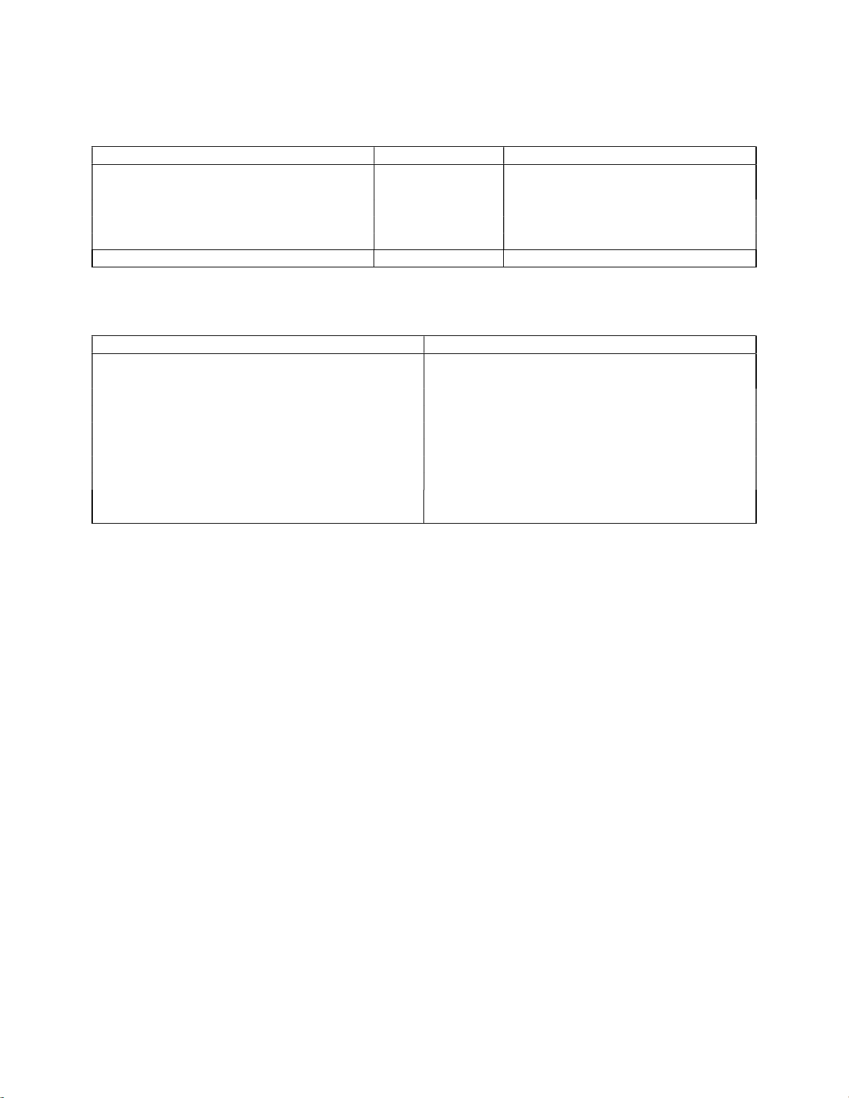
Chemical Poison
The symbol of a liquid dripping
onto a hand shows that a
material
will cause burns or
irritation to
human skin or
tissue
The symbol of a skull and cross bones
shows that a material is poisonous or
is
a danger to life
OPERATION, ORGANIZATIONAL AND INTERMEDIATE MAINTENANCE
WITH ILLUSTRATED PARTS BREAKDOWN
WARNINGS APPLICABLE TO HAZARDOUS MATERIALS
AGITATING PARTS WASHER
PART NUMBER PCS-10/35
1-1
INTRODUCTION
1-2
Warnings for hazardous material listed in this manual are designed to warn personnel of hazards
associated
with such items when they come in contact with them by actual use. For each hazardous
material
used within the facility, a Material Safety Data Sheet (MSDS/SDS) must be provided and available for
review
by users. Consult your local safety and health staff concerning any questions regarding hazardous
materials;
MSDSs; personal protective equipment requirements; and appropriate handling, emergency
procedures
and disposal guidance.
1-3
Under the heading HAZARDOUS MATERIALS WARNINGS, complete warnings, including related icon(s) and
a numeric identifier, are provided for hazardous material used in this manual. Each hazardous material is
assigned only one numeric identifier. Since only those hazardous materials addressed in this manual will
be listed, the numeric identifiers may not appear in sequential order.
1-4
In the text of the manual, the caption WARNING is not used for hazardous material warnings. Hazards are
cited with appropriate icon(s), the nomenclature of the hazardous material, and the numeric identifier
that relates to the complete warning. Users of hazardous materials shall refer to the complete warnings.
EXPLANATION OF HAZARDOUS MATERIAL ICONS
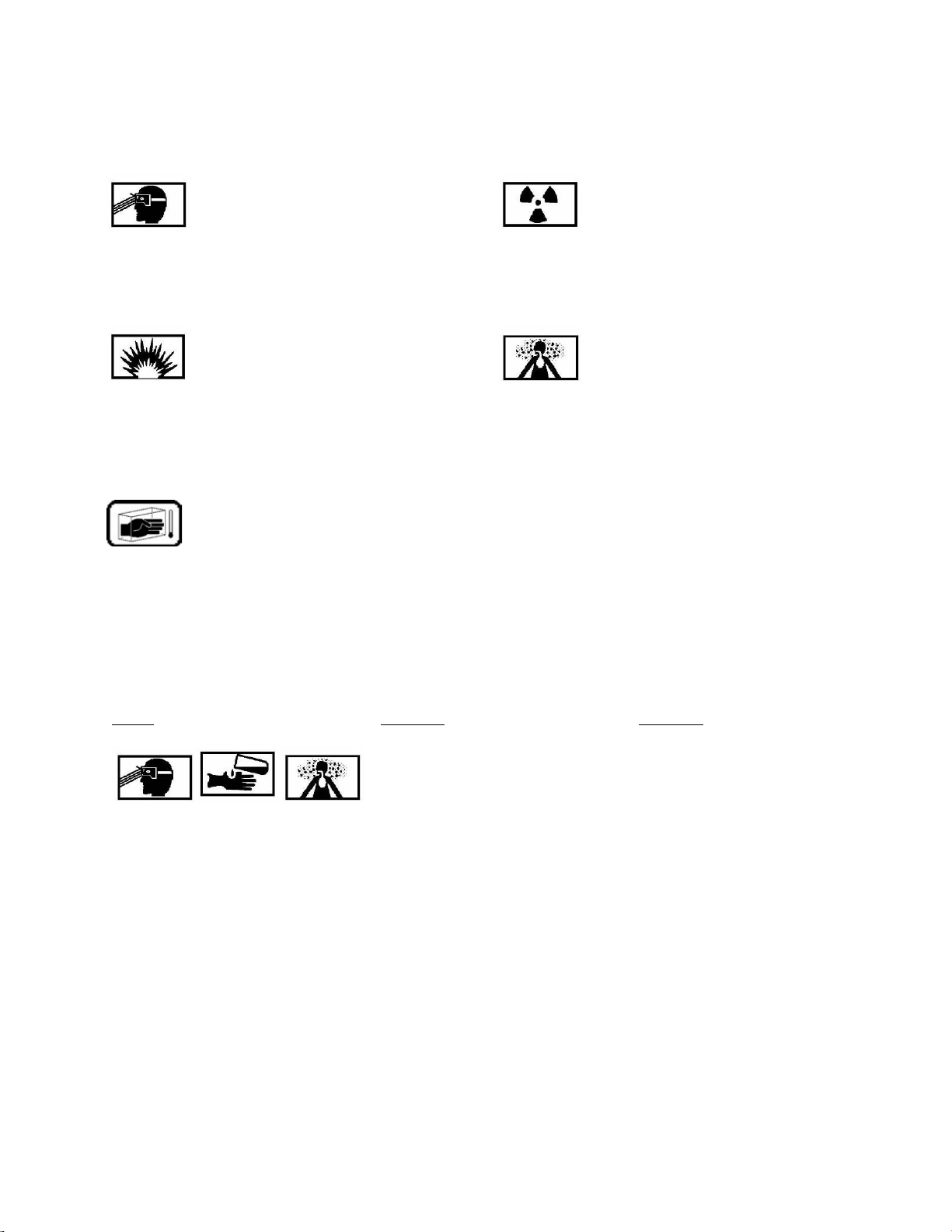
Eye Protection Radiation
The symbol of a person wearing
goggles shows that the material
will injure your eyes.
The symbol of three circular wedges
shows that a material emits radioactive
energy and can injure human skin or
tissue.
Explosion Vapor
The rapidly expanding symbol
shows that the material may
explode if subjected to high
temperatures, sources of ignition,
or high pressure
The symbol of a human figure in a
cloud shows that vapors of a material
present a danger to your life and
health through inhalation.
Cryogenic
The symbol of a hand in a block of
ice shows that the material is
extremely cold and can injure
human skin or tissue.
HAZARDOUS MATERIAL WARNINGS
Index Material Warning
MIL-PRF-680
TYPE II
QUALIFIED
SOLVENT
1. Solvent is combustible. If solvent is decomposed by
heat, toxic gasses are released. Frequent or prolonged
contact may cause dermatitis. Contact may agitate
existing dermal conditions. If contact is made, remove
contaminated clothing. Thoroughly wash affected area
with soap and water; use skin cream if irritation is severe.
Liquid vapor contact may cause eye irritation or tearing or
blurring of vision. Immediately flush eyes with water for
15 minutes. Call a physician if irritation persists. If
solvent is ingested, do not induce vomiting. Immediately
give two glasses of water. Seek medical attention. When
handling solvent wear the approved gloves. If prolonged
contact with mist is likely, wear approved respirator.

PCS
-
10
/
35
Agitating
Parts Washer
1 March 2013
001 00
ALPHABETICAL INDEX
SOLVENT PARTS WASHER
PART NUMBER PCS-10/35
Title WP/Page No.
Air
Cylinder
Assembly
007 00/12
Installation
007 00/12
Removal
007 00/12
Air
Pressure
Bleed
007 00/4
Carbon Filter
Element
(OPTIONAL)
007 00/4
Installation
007 00/5
Removal
007 00/5
Description
003 00/2
Accessories
003 00/3
Agitation Circuit
and Solvent
Filtration Circuit
003 00/2
Air
Filtration Assembly
003 00/2
Operator
Door
Assembly
003 00/2
Operator
Interface
Panel
003 00/3
Pneumatic
Circuit
003 00/3
Service Door
Assembly
003 00/2
Sheet
Metal
Assembly
003 00/2
Tank
Assembly
003 00/2
Door
Switch
007 00/6
Installation
007 00/6
Removal
007 00/6
Fan (OPTIONAL)
007 00/7
Installation
007 00/8
Removal
007 00/7
Filter
Pressure
Gauge
007 00/8
Installation
007 00/8
Removal
007 00/8
Finger
Stock
(OPTIONAL)
007 00/7
Installation
007 00/7
Removal
007 00/7
Float
Switch
007 00/6
Installation
007 00/6
Removal
007 00/6
Fuse
007 00/14
Installation
007 00/14
Removal
007 00/14
Gas
Spring
007 00/7
Installation
007 00/7
1 of 4

PCS
-
10
/
35
Agitating
Parts Washer
1 March 2013
001 00
2
Title
WP/Page No.
Removal
007 00/7
Illustrated
Parts
Breakdown
002 00/3
Description Column
002 00/3
Figure/Index
Number
Column
002 00/3
General
002 00/3
Group Assembly
Parts
List
002 00/3
How
to
Use
the
IPB
002 00/4
Numerical Index
of
Part
Numbers
002 00/4
Part
Number
Column
002 00/3
Part
Number
Column
002 00/4
Code
Column
002 00/4
Units
Per
Assembly
Column
002 00/4
Usable
on
Code
Column
002 00/4
Work
Package/Figure/Index
Number
Column
002 00/4
Introduction
002 00/2
Arrangement
and
Use
002 00/2
Materials
Required
002 00/3
Nonstandard Abbreviations,
Symbols,
and
Terms
002 00/2
Purpose
and Scope
002 00/2
Quality
Assurance
Requirements
002 00/2
Record
of
Applicable
Technical Directives
002 00/2
Reference
Material
002 00/3
Support
Equipment Required
002 00/3
Warnings
Applicable
to
Hazardous
Materials
002 00/2
Introduction
003 00/2
005 00/2
006 00/2
Leading Particulars
003 00/3
LED light
(L1)
007 00/13
Installation
007 00/14
Removal
007 00/13
Metering Valve
007 00/11
Adjustment
007 00/11
Operator
Door
Handle
007 00/7
Installation
007 00/7
Removal
007 00/7
Operator
Interface
Panel
007 00/13
Installation
007 00/13
Removal
007 00/13
PCS
-
10/35
Operation
005 00/4

PCS
-
10
/
35
Agitating
Parts Washer
1 March 2013
001 00
3
Title
WP/Page No.
Enter
Cycle
Time
005 00/4
Preparation for
Storage
or
Shipment
004 00/3
Storage
or
Shipment
004 00/3
Preparation for
Use
004 00/2
Air
Connections
004 00/3
Carbon Filter
Installation
(OPTIONAL)
004 00/3
Disassembly
of
Operator
Door
Handle
004 00/2
Disassembly
of
Air
Cylinder
Assembly
004 00/2
Electrical
Hook
-
Up
004 00/3
Equipment
Damage
004 00/2
Initial Inspection
004 00/2
Installation
004 00/2
Solvent
Selection
004 00/3
Unpacking
004 00/2
Waste
Handling
and
Disposal
004 00/3
Preoperational
Setup
005 00/2
10
-
key
pad
005 00/2
Edit/Clear
005 00/3
ERR: Carriage
Pos.
005 00/3
ERR:
Door
Open
005 00/3
ERR:
Solv
Level
005 00/3
ERR: Carb
Filter
(OPTIONAL)
005 00/3
Exit
005 00/3
F1
(Raise
Carriage)
005 00/2
F2
(Lower
Carriage)
005 00/2
F3
(Pump)
005 00/2
F4
(Fan)
(OPTIONAL)
005 00/2
F5
(MORE
MTCE)
005 00/2
F6
(Reset
Carbon Hours)
(OPTIONAL)
005 00/2
MTCE
005 00/2
MORE
MTCE
005 00/2
Operator
Interface
Panel
005 00/2
Reset
005 00/3
Run/Program
005 00/3
Set
005 00/3
Start
005 00/3
Status
005 00/3
Stop
005 00/3
Time
005 00/3
View/Enter
005 00/3
Preoperational
Setup
006 00/2

PCS
-
10
/
35
Agitating
Parts Washer
1 March 2013
001 00
4
Title
WP/Page No.
Proximity
Switch
007 00/11
Installation
007 00/11
Removal
007 00/11
Pump
007 00/10
Installation
007 00/10
Removal
007 00/10
Repair
Instructions
007 00/4
Service Door
007 00/5
Installation
007 00/5
Removal
007 00/5
Service Door
Gasket
007 00/5
Installation
007 00/6
Removal
007 00/6
Scheduled
Maintenance
007 00/4
Solenoid Valve
Pair
007 00/12
Installation
007 00/13
Removal
007 00/12
Solvent
Filter
Element
007 00/5
Installation
007 00/5
Removal
007 00/5
Solvent
Filter
Housing
(Front)
007 00/8
Installation
007 00/9
Removal
007 00/8
Solvent
Filter
Housing (Rear)
007 00/9
Installation
007 00/9
Removal
007 00/9
Solvent
Replacement
007 00/4
Spray
Bar
Nozzles
007 00/10
Installation
007 00/10
Removal
007 00/10
Testing
and
Troubleshooting
006 00/2
Theory of Operation 003 00/2
Transient Voltage Surge Suppressor (TVSS) (OPTIONAL) 007 00/14
Installation
007 00/14
Removal
007 00/14
Troubleshooting 007 00/4
Unscheduled Maintenance 007 00/4

PCS
-
10
/
35
Agitating
Parts Washer
1 March 2013
001 01
1
of
4
PART
NUMBER
WP NO./FIG.
NO./INDEX NO.
109321
007 00/2/11
109329
007 00/2/15
109335
007 00/2/14
109338 007 00/5/8
109339
007 00/3/4
109340 007 00/5/12
109341
007 00/3/3
109342 007 00/5/13
109343 007 00/4/7
109351
007 00/2/4
007 00/2/7
007 00/2/10
007 00/2/13
007 00/2/17
007 00/2/20
007 00/2/23
007 00/4/3
007 00/4/9
007 00/4/21
007 00/9/6
007 00/10/8
109352 007 00/5/17
109355 007 00/5/7
007 00/5/11
109366 007 00/4/11
109371 007 00/4/10
109377 007 00/4/15
109378
007 00/2/18
109379
007 00/2/21
109384 007 00/8/20
109388 007 00/8/24
109390
007 00/1/11
109393
007 00/3/2
109410
007 00/10/1
109411
007 00/10/2
NUMERICAL INDEX OF PART NUMBERS
SOLVENT PARTS WASHER
PART NUMBER PCS-10/35
PART
NUMBER
WP NO./FIG.
NO./INDEX
NO.
PCS
-
10/35
007 00/1
WP-680SR 007 00/7/3
107136 007 00/9/35
107215 007 00/7/1
107216 007 00/7/5
107223 007 00/9/23
107305 007 00/5/6
007 00/5/10
007 00/5/19
007 00/8/3
007 00/8/23
007 00/8/27
007 00/9/8
007 00/10/9
107628 007 00/8/1
109264
007 00/1/1
007 00/2
109265
007 00/2/2
109266
007 00/2/5
109270
007 00/2/1
109274
007 00/1/2
007 00/3
109275
007 00/3/1
109276 007 00/5/1
109278 007 00/5/3
109279 007 00/5/2
109282 007 00/4/1
109289
007 00/1/3
007 00/4
109290
007 00/1/4
007 00/5
109293 007 00/5/4
109316 007 00/4/4
109319 007 00/8/28
109320
007 00/2/8

PCS
-
10
/
35
Agitating
Parts Washer
1 March 2013
001
01
2
PART
NUMBER
WP NO./FIG.
NO./INDEX NO.
109524 007 00/9/24
109526 007 00/9/25
109528 007 00/9/28
109530 007 00/9/29
109532 007 00/9/26
109537 007 00/9/27
109539 007 00/4/23
109541 007 00/4/22
109547
007 00/1/9
007 00/10
109548 007 00/7/4
109559 007 00/4/24
109561 007 00/11/1
109562 007 00/11/3
109563 007 00/11/5
109564 007 00/11/7
109565 007 00/11/8
109566 007 00/11/9
109567 007 00/11/10
109568 007 00/11/11
109569 007 00/11/12
109570 007 00/11/13
109572 007 00/11/14
109590
007 00/10/13
109611
007 00/10/10
109618
007 00/10/3
109619
007 00/1/10
007 00/11
109621
007 00/2/3
007 00/2/6
007 00/2/9
007 00/2/12
007 00/2/16
007 00/2/19
007 00/2/22
007 00/2/25
007 00/4/2
007 00/4/8
007 00/4/20
PART
NUMBER
WP NO./FIG.
NO./INDEX NO.
109412 007 00/5/24
109413 007 00/5/20
109414
007 00/2/24
109416 007 00/4/19
109419 007 00/9/5
109425 007 00/4/6
007 00/5/27
007 00/9/12
109426
007 00/1/12
109427 007 00/9/1
109434
007 00/1/6
007 00/7
109442 007 00/7/6
109445 007 00/7/11
109446 007 00/7/8
109447 007 00/7/9
109448 007 00/7/12
109451 007 00/7/13
109453 007 00/7/14
109464 007 00/7/15
109469
007 00/1/7
007 00/8
109472 007 00/8/7
109474 007 00/8/4
109475 007 00/8/5
109499 007 00/9/2
109500 007 00/9/3
109505 007 00/9/4
109512 007 00/9/16
109513 007 00/9/14
109514 007 00/9/10
109515 007 00/9/15
109516
007 00/1/8
007 00/9
109518 007 00/9/19
109519 007 00/9/17
109520 007 00/9/18
109522 007 00/9/21
109523 007 00/9/22

PCS
-
10
/
35
Agitating
Parts Washer
1 March 2013
001
01
3
PART
NUMBER
WP NO./FIG.
NO./INDEX NO.
109682
007 00/10/6
109683
007 00/10/4
109685 007 00/8/6
109700
007 00/10/17
109701
007 00/10/18
109702
007 00/10/19
109704 007 00/9/33
109706
007 00/10/20
109708
007 00/10/21
109709 007 00/6/6
109712
007 00/10/12
109713
007 00/10/11
109717 007 00/8/8
109719 007 00/8/9
109720 007 00/8/10
109721 007 00/8/11
109722 007 00/8/19
109723 007 00/8/15
109724 007 00/8/16
109725 007 00/8/17
109726 007 00/8/12
109729 007 00/8/13
109731 007 00/8/14
109733 007 00/8/18
109735 007 00/7/10
109737 007 00/5/25
109738 007 00/5/28
109741 007 00/6/4
109745 007 00/6/7
109749
007 00/1/13
109754
007 00/10/14
109755
007 00/10/15
109756
007 00/10/16
109759 007 00/4/25
109760 007 00/6/9
109767
007 00/10/22
109770 007 00/7/16
109774 007 00/6/11
PART
NUMBER
WP NO./FIG.
NO./INDEX NO.
007 00/5/5
109621 007 00/5/9
109621 007 00/5/18
007 00/8/2
007 00/8/21
007 00/8/25
007 00/9/7
007 00/10/7
109622
007 00/2/26
109623 007 00/4/5
007 00/4/12
007 00/4/16
007 00/5/26
109623 007 00/9/11
109624 007 00/7/2
109628 007 00/4/14
007 00/4/18
007 00/6/7
007 00/6/14
007 00/9/13
109629 007 00/5/14
007 00/5/21
109630 007 00/5/16
007 00/5/23
109631 007 00/5/15
007 00/5/22
109632 007 00/8/22
007 00/8/26
109633 007 00/9/9
109634 007 00/11/2
007 00/11/4
007 00/11/6
109650
007 00/1/5
007 00/6
109654 007 00/6/2
109661 007 00/6/3
109663 007 00/6/5
109670 007 00/6/10
109676
007 00/10/5

PCS
-
10
/
35
Agitating
Parts Washer
1 March 2013
001
01
4
PART
NUMBER
WP NO./FIG.
NO./INDEX NO.
109775 007 00/6/12
109776 007 00/6/13
109779 007 00/8/29
109780 007 00/8/30
109785 007 00/9/30
109786 007 00/9/31
109787 007 00/9/32
109842 007 00/4/13
007 00/4/17
109843 007 00/11/15
109867 007 00/7/7
109870 007 00/9/34
109982 007 00/9/20
109984 007 00/9/36
109985
007 00/10/23
109986 007 00/6/1
109990 007 00/5/31
109991 007 00/5/29
109992 007 00/5/30

PCS
-
10
/
35
Agitating
Parts Washer
1 March 2013
001
02
Page
1
of
2
(2
blank)
NUMERICAL INDEX OF REFERENCE DESIGNATORS
SOLVENT PARTS WASHER
PART NUMBER PCS-10/35
REF DES
WP NO./FIG
NO./INDEX NO.
PART NUMBER
F1
(Fuse)
007
00/10/16
109756
F2
(Fuse)
007
00/10/15
109755
F3
(Fuse)
007
00/10/14
109754
L1
(LED
light)
007
00/10/2
109411
L2 (E-stop light) 007 00/10/3 109618
M1
(pump)
007
00/8/1
107628
M2
(fan
motor)
007
00/6/6
109709
TVSS (OPTIONAL) 007 00/10/18 109701

THIS PAGE INTENTIONALLY LEFT BLANK

PCS
-
10
/
35
Agitating
Parts Washer
1 March 2013
002
00
Page
1
of
8
(8
blank)
INTRODUCTION
SOLVENT
PARTS WASHER
PART
NUMBER PCS-10/35
Alphabetical Index
Title Page No.
Illustrated Parts Breakdown
3
Description Column
3
Figure/Index Number Column
3
General
3
Group Assembly Parts List
3
How to Use the IPB
4
Numerical Index of Part Numbers
4
Part Number Column
3
Part Number Column
4
SM& R Code Column
4
Units Per Assembly Column
4
Usable on Code Column
4
Work Package/Figure/Index Number Column
4
Introduction
2
Arrangement and Use
2
Materials Required
3
Nonstandard Abbreviations, Symbols, and Terms
2
Purpose and Scope
2
Quality Assurance Requirements
2
Record of Applicable Technical Directives
2
Reference Material
3
Requisitioning
and
Automatic
Distribution
of
2
Support
Equipment Required
3
Warnings Applicable to Hazardous Materials
2

PCS
-
10
/
35
Agitating
Parts Washer
1 March 2013
002
00
2
INTRODUCTION
SOLVENT
PARTS WASHER
PART
NUMBER PCS-10/35
1.
INTRODUCTION
PURPOSE AND SCOPE. This manual contains
operation and intermediate maintenance
instructions with detailed parts lists for the PCS-
10/35
Solvent Parts Washer. This section lists all the
special tools and test
equipment required for testing
and maintaining the
PCS-10/35.
2.
3. ARRANGEMENT AND USE. This manual is
broken down into separate work packages (WPs)
which detail specific major subassemblies and
operations necessary for maintenance of the PCS-
10/35
Solvent Parts Washer. General information,
operation, and routine
maintenance are covered in
the first six WPs of the
manual. The following WPs
cover detailed
maintenance and repair, and include
repair parts
lists. Each WP is assigned a five-digit
number, which,
with its applicable publication
number, provides a
means of locating a specific WP
in a manual. To find
a WP when only the subject
matter is known, refer
to the alphabetical index
(001 00).
4.
WARNINGS APPLICABLE TO HAZARDOUS
MATERIALS. Warnings applicable to hazardous
materials used in this manual are listed in the
Hazardous Materials Warning Sheet (HMWS).
5.
QUALITY ASSURANCE REQUIREMENTS.
Certain procedures or steps of procedures in this
manual may be followed by “(QA)” indicating a
quality assurance phase. These procedures, if
improperly performed, will affect equipment
performance or safety of personnel. A quality
assurance inspection of each procedure or step
followed by “(QA)” shall be performed before
proceeding to the next step, unless it can be
determined that such inspection can be performed
after completion of the entire procedure.
6.
OPTIONAL EQUIPMENT. The PCS-10/35 can
be
equipped with optional equipment to enhance
performance. The air filtration assembly system
(carbon filter and fan), agitation system (spray bars
and a higher capacity pump), EMI suppression
system and the foundation weld bracket are optional
features that are included in this manual. When an
optional feature is discussed, it is notated with
(OPTIONAL).
7.
If additional or replacement copies of this
manual are required they may be ordered from
Clarus Fluid Intelligence at
info@clarustechnologies.com
or by calling 360-715-
1356.
8.
SUPPORT EQUIPMENT REQUIRED. Table 2
lists all support equipment required to perform the
maintenance procedures in this manual.
9.
MATERIALS REQUIRED. Consumable
materials and expendable items required to
accomplish prescribed maintenance are listed in
Table 4. Suitable equivalent items may be
substituted unless noted otherwise.
10.
ILLUSTRATED PARTS BREAKDOWN.
11.
GENERAL. The IPB provides information
necessary for requisitioning, identifying parts, and
illustrating disassembly and assembly relationships.
12.
GROUP ASSEMBLY PARTS LIST. The group
assembly parts list (GAPL) consists of a breakdown of
the item into assemblies and detail parts. Attaching
parts are identified immediately following the item
they attach. The GAPL uses a six column format. All
symbols and abbreviations used in the GAPL are in
accordance with MIL-STD-12, Abbreviations for Use
on Drawing and in Specifications, Standards and
Technical Documents.
13.
FIGURE/INDEX NUMBER COLUMN. In this
column, index numbers are assigned in numerical
sequence. The index numbers are used on the
illustration(s) to locate the item.
14.
PART NUMBER COLUMN. This column lists
manufacturer part numbers, government standard
part numbers, or other vendor part numbers.
15.
DESCRIPTION COLUMN. The description
column lists item nomenclature, plus modifiers
necessary to identify the item. The assemblies,

PCS
-
10
/
35
Agitating
Parts Washer
1 March 2013
002
00
3
subassemblies, detail parts, and attaching parts are
properly identified (named and indented) to show
their relationship to the item. The description may
include special notes in slashes “(/ /)” to explain or
clarify any unique conditions that pertain to the
item.
a.
Attaching parts are listed immediately after
the part they attach, and precede any
breakdown of the item attached. The caption
“ATTACHING PARTS” appears in the description
column, preceding the attaching parts. The
symbol “---*---“ is used to indicate the end of
the attaching parts for a specific assembly or
part.
b.
The notation “(See Figure for bkdn)”
following the description of a part number
indicate that further breakdown of the part is
shown in the figure noted.
c.
The notation “(NHA, Fig. )” following the
description of a part number indicates that the
correct next higher assembly relationship of
the part is shown in the figure noted.
d.
The notation “(use only on)” following the
description of a part number indicates that the
part is used only on the particular assembly
noted.
e.
Make From. When an item is coded for
local manufacture, the material from which it is
made is included following the item
nomenclature.
f.
Manufacturers that have not yet been
assigned CAGE codes by the government are
identified herein by a temporary CAGE
identifier. Temporary CAGE identifiers are 5-
digit codes comprised of Arabic numbers
preceded by a series of dashes. The identifier -
---1 is representative of the first used in a
publication.
16.
UNITS PER ASSEMBLY COLUMN. This
column lists the quantity of each part required per
assembly and is not necessarily the total number
used in the end item of equipment. Quantities of
attaching parts are listed per assembly,
subassembly, or part attached. The letters “AR” (as
required) are used to identify bulk items. The
abbreviation “REF” indicates that the part is listed
elsewhere in the IPB and that it is included in the
present listing for reference only.
17.
USABLE ON CODE COLUMN. This column
indicates the usability of parts on different models or
series of the equipment. Codes appear as uppercase
letters. If no letter appears in this column, the part
may be used on all models/series of the equipment.
Usable on codes are listed and defined in the WP
containing the IPB.
18.
Interchangeable Parts. Interchangeable
parts have the same index number and
nomenclature and are denoted by an asterisk (*) in
the Usable On Code column of the GAPL. When all
parts of an index number are asterisked, they are
completely interchangeable and no part is
preferable. When one of these parts is a preferred
replacement, it appears last without an asterisk in
the Usable On Code column. The appearance of an
asterisk and a usable on code (for example, *B)
indicates that interchangeability is limited to the
extent of the usable on code.
19.
NUMERICAL INDEX OF PART NUMBERS.
The numerical index of part number (WP 001 01) is a
complete alphanumerical tabulation of part
numbers, or names if part numbers have not been
assigned.
20.
PART NUMBER COLUMN. This column lists
all part number that appear in the part number
column of the GAPL. The column also lists the
identifying noun name in lieu of a part number when
no part number has been assigned. Part numbers
are listed in alphanumerical sequence.
21.
WORK PACKAGE / FIGURE / INDEX NUMBER
COLUMN. This column lists the WP, figure, and
i n d ex
numbers assigned to the associated part
number. The numbers are separated by slashes, the
first number representing the work package in which
the part number is located. The second number
represents the figure that illustrates the part in
question, and the third number is the index number
identifying the part within the figure.
22.
HOW TO USE THE IPB. The following
paragraphs describe how to obtain specific
information from the IPB.

PCS
-
10
/
35
Agitating
Parts Washer
1 March 2013
002
00
4
23.
When The Part Number is Not Known.
Proceed as follows:
a.
Determine the function and application of
the part required.
b.
Select the most appropriate IPB figure title.
c.
Turn to the figure indicated and locate the
desired part on the illustration.
d.
From the illustration, obtain the index
number assigned to the part desired.
24.
Refer to the GAPL for the identifying name
and any other specific information, including the
part number.
25.
When The Part Number is Known. Proceed
as follows:
a.
Refer to the numerical index of the part
numbers (WP 001 01).
b.
Locate the part number and note the WP,
figure, and index number assigned to the
part number.
c.
Turn to the WP and figure indicated and
locate the number referenced.
If a pictorial representation or a location of the part
is desired, refer to the same index number on the
accompanying illustration.
6
TABLE 2. SUPPORT EQUIPMENT REQUIRED
Nomenclature
CAGE
Code
Part
Number
Container, waste (1 gallon).
---
Container,
waste
(minimum
40
gallon)
---
Forklift.
---
Welder
(OPTIONAL)
---
TABLE 3. MATERIALS REQUIRED
Nomenclature
Specification/Part
No.
Alcohol, Isopropyl
109628
Nut,
¼
-
20
,
Nylock,
SS
Nut,
5/16
-
18
18
-
8
Nylock,
SS
107305
Rag,
wiping
---
Screw
109634
Solvent
MIL
-
PRF
-
680
Type
II
Sealant,
thread
A
-
A
-
58092
String
or
duct
tape
---

THIS PAGE INTENTIONALLY LEFT BLANK
This manual suits for next models
1
Table of contents
Other Clarus Cleaning Equipment manuals

Popular Cleaning Equipment manuals by other brands

Wetrok
Wetrok Monovac Comfort 6/11 operating instructions

Rexair
Rexair Rainbow Squeegee manual

ICE COBOTICS
ICE COBOTICS ICE USA i20NBL Operator's & parts manual

Elma
Elma Elmasonic xtra TT operating instructions

Light Progress
Light Progress UV-DUCT-FL 2/35HP-NX manual

Sola-Tecs
Sola-Tecs F Series Assembly instructions


Nilfisk-Advance
Nilfisk-Advance Topax Hygiene System user guide

Mod-U-Blast
Mod-U-Blast Twister HD Operation & maintenance manual

TEGRAS Concept
TEGRAS Concept iFoam Mini user manual

ThermaCor
ThermaCor Thermax Therminator DV12 Owner's/operator's manual

RIDGID
RIDGID 0095691386786 manual

Kärcher
Kärcher WV 70 plus manual